Table of Contents
Advertisement
Available languages
Available languages
Advertisement
Chapters
Table of Contents

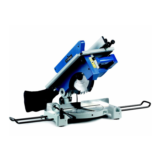
Related Manuals for Fox F36-075


Summary of Contents for Fox F36-075
- Page 1 TRONCATRICE CIRCOLARE MITRE SAW D 210 Modello Fox F36-075 Fox model F36-075...
- Page 2 SOMMARIO / INDEX ITALIANO (IT) 3÷24 Manuale originale, Original manual ENGLISH (EN) 25÷46 Manual translated from the original, Manuale tradotto dall’originale DICHIARAZIONE DI CONFORMITA / DECLARATION OF CONFORMITY ESPLOSO / EXPLODED VIEW SCHEMA ELETTRICO / WIRING DIAGRAM...
-
Page 3: Table Of Contents
SOMMARIO • Sicurezza Pag. 4 • Regole generali di sicurezza Pag. 5 • Regole supplementari di sicurezza per le troncatrici Pag. 7 • Norme di sicurezza per i rischi residui Pag. 8 • Protezione dell’ambiente Pag. 9 • Simboli Pag. 9 •... -
Page 4: Sicurezza
SICUREZZA ATTENZIONE: Quando si utilizzano utensili elettrici si dovrebbero sempre rispettare, oltre a quelle riportate in questo manuale, tutte le precauzioni base di sicurezza per ridurre il rischio di incendio, scossa elettrica e danni personali. Leggere attentamente tutte queste istruzioni prima di utilizzare questo prodotto e conservarle scrupolosamente. -
Page 5: Regole Generali Di Sicurezza
REGOLE GENERALI DI SICUREZZA 1. Mantenete l’area di lavoro pulita. Nelle zone o nei banchi di lavoro ingombri è più alta la probabilità di incidenti. 2. Evitate un ambiente pericoloso. Non esponete gli utensili alla pioggia e non utilizzateli in ambienti umidi o bagnati, per evitare i fenomeni di elettrolocuzione. Mantenete la zona di lavoro ben illuminata. - Page 6 16. Non forzate l’utensile. La lavorazione sarà migliore e maggiormente sicura se l’utensile viene utilizzato al ritmo per il quale è stato concepito. 17. Utilizzate l’utensile appropriato. Non forzate un piccolo utensile a fare il lavoro di un utensile a utilizzo intensivo. Per esempio, non utilizzate una sega circolare per tagliare dei rami o dei ceppi.
-
Page 7: Regole Supplementari Di Sicurezza Per Le Troncatrici
REGOLE SUPPLEMENTARI DI SICUREZZA PER LE TRONCATRICI 1. Non usare la troncatrice se le protezioni non sono in posizione, specialmente dopo aver effettuato il cambio di modo; assicurarsi che sia in perfetta efficienza e che venga fatta la regolare manutenzione. 2. -
Page 8: Norme Di Sicurezza Per I Rischi Residui
NORME DI SICUREZZA PER I RISCHI RESIDUI Non forzate inutilmente la macchina: una pressione di taglio eccessiva può provocare un rapido deterioramento della lama ed un peggioramento delle prestazioni della macchina in termini di finitura e di precisione di taglio. - Nel taglio dell’alluminio e materie plastiche usate sempre gli appositi morsetti: i pezzi oggetto di taglio devono sempre essere tenuti fermamente nella morsa. -
Page 9: Protezione Dell'ambiente
PROTEZIONE DELL’AMBIENTE INFORMAZIONE AGLI UTENTI Ai sensi dell’art. 13 del Decreto Legislativo 25 luglio 2005, n. 151 “Attuazione delle Direttive 2002/95/CE, 2002/96/CE, e 2003/108/CE, relative alla riduzione dell’uso di sostanze pericolose nelle apparecchiature elettriche ed elettroniche, nonché allo smaltimento dei rifiuti”, si precisa quanto segue: •... -
Page 10: Collegamento Dell'utensile Alla Corrente
Prodotto conforme alle norme relative della CE. Doppio isolamento. Questo simbolo significa che nessun elemento che può condurre la corrente è accessibile senza l’utilizzo di un utensile. Questi apparecchi sono privi di conduttore di terra. Matricola/anno costruzione Divieto accesso, zona pericolosa COLLEGAMENTO DELL’UTENSILE ALLA CORRENTE ALLACCIAMENTO ELETTRICO Per l’alimentazione della vostra macchina è... -
Page 11: Descrizione Della Macchina
ATTENZIONE: TENETE GLI UTENSILI E LE ATTREZZATURE FUORI DALLA PORTATA DEI BAMBINI. ATTENZIONE: L’ impianto elettrico della vostra segatrice è dotato di relè di minima tensione, che apre automaticamente il circuito quando la tensione scende sotto un minimo prestabilito, e che impedisce il ripristino automatico della condizione di funzionamento quando la tensione ritorna ai livelli nominali previsti. -
Page 12: Caratteristiche Tecniche
USO NON CONSENTITO Non è adatta per il taglio di: - MATERIALI FERROSI, ACCIAI E GHISE E DI QUALSIASI ALTRO MATERIALE DIVERSO DA QUELLI SPECIFICATI NELL’USO CONSENTITO, ED IN PARTICOLARE DI SOSTANZE ALIMENTARI. - SEGA CIRCOLARE SENZA PROTEZIONE LAMA. CARATTERISTICHE TECNICHE Potenza motore: 1200 W S1 Tensione di alimentazione e frequenza:... -
Page 13: Descrizione Dei Componenti Della Macchina
DISIMBALLO (Fig. 2) Nell’imballo della sega sono presenti: 1 – Troncatrice 2 – Chiavi per la sostituzione lama 3 – Chiave a brugola 5 mm 4 – Estensioni piano (n°2) 5 – Morsa orizzontale 6 – Protezione supplementare inferiore 7 – Spintore 8 –... -
Page 14: Regolazioni
REGOLAZIONI ATTENZIONE! Prima di effettuare qualsiasi operazione di regolazione, manutenzione, pulizia, cambio lama sulla sega assicuratevi che questa sia spenta e scollegata da qualsiasi fonte di corrente. Quando tutte le regolazioni sono state effettuate, assicuratevi che tutte le chiavi e gli utensili siano lontani dalla macchina, e che tutte le viti, i bulloni e gli altri dispositivi di fissaggio siano bloccati correttamente. -
Page 15: Regolazione Altezza Piano Superiore
REGOLAZIONE ALTEZZA PIANO SUPERIORE (FIG. 5 – 6 – 7 – 7A) SOLO PER SEGA CIRCOLARE ATTENZIONE: Lavorando sul piano superiore, è necessario montare il carter di protezione supplementare inferiore 23 in dotazione. Per applicare il carter di protezione supplementare inferiore 23: - applicare la protezione supplementare posizionandola nell’... -
Page 16: Regolazione Della Squadra Di Appoggio
REGOLAZIONE DELLA SQUADRA DI APPOGGIO (FIG. 8) SOLO PER SEGA CIRCOLARE Potete avvicinare o allontanare la squadra di appoggio 14 dalla lama, in modo da eseguire il taglio di tavole di misura prestabilita. Allentate il volantino 26, e fate scorrere la squadra 14, facendo coincidere la superficie della squadra con la rispettiva posizione sulla scala graduata del piano di lavoro, posizione che corrisponde alla effettiva distanza dell’appoggio della squadra con la lama. -
Page 17: Regolazione Degli Angoli Di Taglio
REGOLAZIONE DEGLI ANGOLI DI TAGLIO (Fig. 9 – 10) CONTROLLO E REGOLAZIONI ANGOLI DI TAGLIO : Per effettuare regolazioni sugli angoli di taglio, procedete come di seguito specificato: 90° Orizzontale e verticale • Per il 90° orizzontale allentare i bulloni (B1-B2) situati sull’ appoggio angolare 18 utilizzando una chiave a brugola;... -
Page 18: Spostamento Della Segatrice
Alle estremità della base della segatrice sono presenti quattro fori per fissarla ad un piano o ad un’altra superficie d’appoggio. Se la segatrice deve essere spostata spesso, montatela su una base di legno compensato (spessa almeno 20 mm) che potrete così fissare con dei morsetti a vite a qualsiasi superficie di appoggio. -
Page 19: Uso Come Sega Circolare
- Ponete la mano destra sull’impugnatura 1, e premete il pulsante 9 in modo da sbloccare il movimento della testa. - Azionate il motore con il pulsante di marcia 2 sull’impugnatura. - Fate scendere la testa, e mettete gradualmente a contatto la lama con il pezzo da tagliare. - Eseguite il taglio completo del pezzo, e riportate la testa nella posizione originale. -
Page 20: Montaggio E/O Sostituzione Della Lama
Fig.12 - Con motore spento, bloccate la testa della macchina in posizione abbassata, tramite il perno di blocco 16. - Regolate l’altezza del piano superiore in base all’altezza di taglio voluta e la squadra di appoggio come descritto al paragrafo “REGOLAZIONI ALTEZZA PIANO SUPERIORE e REGOLAZIONI SQUADRA APPOGGIO”. -
Page 21: Scelta Della Lama
Fig.13 Fig.14 Alzate il piano superiore fino alla sua massima altezza. Svitare la vite 28 che si trova sulla parte destra della troncatrice dietro al motore, e far ruotare il carter mobile 11 liberando completamente la lama. Con la testa in posizione di riposo (rialzata), bloccare la flangia esterna 29 con la chiave in dotazione, e con la chiave a tubo svitare la vite a testa esagonale in senso orario. -
Page 22: Manutenzione
La sega è predisposta per il montaggio di un sacchetto raccogli polvere da montare con una fascetta sul bocchettone posteriore o di un aspiratore esterno, da attaccare sempre nello stesso punto e che permette una più efficiente raccolta. Si consiglia comunque l’utilizzo di una mascherina protettiva. MANUTENZIONE AVVERTENZA: Spegnete l’interruttore e scollegate la troncatrice dalla corrente, togliendo la spina del cavo dalla presa di corrente prima di qualsiasi regolazione, riparazione, manutenzione... -
Page 23: Guida Alla Localizzazione Dei Guasti
bruciato o danneggiato. Se le spazzole sono ancor utilizzabili dopo l’ispezione, rimontatele nella posizione originaria. GUIDA ALLA LOCALIZZAZIONE DEI GUASTI PROBLEMA PROBABILE CAUSA RIMEDIO SUGGERITO Il motore non funziona Motore, cavo rete o spina Fate controllare la macchina difettosi. da personale specializzato. Non cercate di riparare da soli il motore: potrebbe essere pericoloso. -
Page 24: Assistenza
ASSISTENZA Tutti gli utensili e accessori Fox sono costruiti e controllati utilizzando le più moderne e sicure tecniche produttive. Se nonostante queste attenzioni un utensile dovesse guastarsi la riparazione deve essere fatta da un centro riparazioni autorizzato Delta France. L’elenco dei centri assistenza è reperibile presso i vari punti vendita o telefonando a... - Page 25 INDEX • Safety instructions • General safety instructions • Specific safety instructions for mitre saws • Safety instructions for further risks • Environmental protection • Symbols • Electrical connections • Machine description • Technical specifications • Noise conditions • Removal of package •...
-
Page 26: Safety Instructions
SAFETY INSTRUCTIONS CAUTION: Besides following the instructions mentioned in this manual, when using electric equipment you must always observe all safety precautions to prevent risk of fire, electric shock and personal injury. Read this instruction manual before use and keep it carefully. The probability of risk can be reduced by the machine safety equipment of the machines, as for example protections, blade case, clamping, stoppage and the personal protection devices as protective goggles, dust mask, ear plugs, protective shoes and gloves. -
Page 27: General Safety Instructions
41. Use the suitable tool for the work you are processing. Do not use a small tool for an intensive job. Fox example, do not use a circular saw to cut branches or stumps. - Page 28 42. Block the piece. If possible, use C-clamps or a holder to fix the piece. It is safer than using only your hands. 43. Keep the tools in perfect conditions. Keep the tools sharp and clean to obtain better and safer results.
-
Page 29: Specific Safety Instructions For Mitre Saws
SPECIFIC SAFETY INSTRUCTIONS FOR MITRE SAWS 1. Do not use the saw without the protection devices in position, especially after changing mode; ensure that it is perfectly efficient and properly maintained. 2. Replace the table insert when worn. 3. Do not use saw blades which are damaged or deformed. 4. -
Page 30: Safety Instructions For Further Risks
SAFETY INSTRUCTIONS FOR FURTHER RISKS - Do not force the machine unnecessarily: excessive cutting pressure may lead to rapid deterioration of the blade and a decrease in performance in terms of finish and cutting precision. - When cutting aluminium and plastics always use the appropriate clamps: all workpieces must be clamped down firmly. -
Page 31: Environmental Protection
ENVIRONMENTAL PROTECTION INFORMATION FOR USERS In accordance with art. 13 of Legislative Decree 25th July 2005, no. 151 “Implementation of Directives 2002/95/EEC, 2002/96/EEC and 2003/108/EEC, relative to reducing the use of hazardous substances in electric and electronic appliances and the disposal of waste”, please take note of the following: •... -
Page 32: Electrical Connections
Double insulation. This symbol means that you cannot get at any element carrying the electrical current without using a tool. Tools which have this symbol do not have any earthing protection systems. Serial number / Year of production Keep your hands away / dangerous area ELECTRICAL CONNECTIONS ELECTRICAL CONNECTIONS Use 230 V 50 Hz alternate voltage to supply your machine. - Page 33 WARNING: Your mitre-saw’s electrical system is equipped with an undervoltage relay which automatically opens the circuit when the voltage falls below a minimum pre-established limit and which prevents the self-reset of the machine functions when voltage returns to normal levels. If the machine stops involuntarily, do not be alarmed and make sure that there has not been a voltage failure in the electrical system.
-
Page 34: Technical Specifications
TECHNICAL SPECIFICATIONS Engine power: 1200 W S1 Voltage and frequency: 230 V - 50 Hz Speed: 4500 RPM. Saw blade maximum dimensions: 210 x 30 x 2,5 mm (24 teeth) Crosscut at 90°: 57 x 120 mm Oblique cutting 45°: 55 x 70 mm Inclined cutting 45°: 43 x 120 mm... - Page 35 REMOVAL OF PACKAGE (Fig. 2) The parts included in the package are: 1 – Mitre saw 2 – Wrenches for replacing the blade 3 – 5 mm Allen wrench 4 – Workbench extensions (n°2) 5 – Horizontal clamp 6 – Additional lower protection 7 –...
- Page 36 ADJUSTMENTS CAUTION! Be sure that the mitre saw is switched off and disconnected from any current source before any adjustment, maintenance or cleaning work and before changing the blade. After carrying out all the adjustments, ensure that all wrenches and tools are away from the machine, and that all screws, bolts and other locking devices are correctly blocked.
- Page 37 ADJUSTMENT OF UPPER SURFACE’S HEIGHT (Fig. 5-6-7-7A) JUST FOR CIRCULAR SAW ATTENTION: When working on the upper surface, it is absolutely necessary to install the lower protective cap 23 supplied. To install the additional protective cap 23: - install the additional protective cap by inserting it into the slot provided (Fig. 7); - place and then lock the head with the locking pin 16;...
- Page 38 Loosen the handwheel 26 and slide the bracket 14, while aligning the index on the bearing with its corresponding position on the graduated scale on the work surface. This position corresponds to the actual distance from the bearing bracket to the blade. Fig.8A Fig.
- Page 39 ADJUSTMENT OF CUTTING ANGLES (Fig. 9 – 10) CHECK AND ADJUSTMENT OF CUTTING ANGLES: If you have to carry out any adjustment, follow the instructions below: 90° horizontal and vertical • To obtain an angle of 90° between the fence and the blade loosen the bolts (B1-B2) located on the fence 18 by using an Allen wrench;...
-
Page 40: Transportation Of The Mitre Saw
adjustments in the safer possible conditions and with a sufficient swinging room. Fix the machine to the bench by using the four holes located on the base. Before use, the mitre saw must be firmly fixed to a plane surface. At the base’s ends there are four holes to fix it to a plane or to a bearing surface. - Page 41 - Actuate the motor with the main switch start button 2 on the handgrip. - Lower the head and gradually bring the blade into contact with the workpiece. - Complete cutting and raise the head to its original position. - Turn off the motor by releasing the main switch button 2. WARNING! If cutting with double inclination (rotation and inclination of the head) keep the workpiece firmly against the machine with your right hand and lower the head with your left hand...
- Page 42 Fig.12 - When the motor is off, lower the machine head and block it by means of the locking pin 16. - Adjust the height of the upper work surface according to the cutting height desired and adjust the bearing bracket as described in the paragraph “ADJUSTMENT OF UPPER SURFACE’S HEIGTH”...
-
Page 43: Selection Of The Blade
Fig.13 Fig.14 Raise the upper surface to its maximum height. Loosen the screw 28 located on the right side of the mitre saw behind the motor, and turn the moving protection 11 to completely release the blade. While the head is in the rest position (raised), lock the outer flange 29 with the wrench provided, and unbolt the hexagonal-head screw clockwise with the hexagonal spanner. - Page 44 MAINTENANCE CAUTION: Before any adjustment, repair, maintenance work and before replacing the blade, switch off the machine and disconnect it from the power supply by removing the plug from the socket. In case you find out any damage to the protection devices or irregularities while processing or checking the machine, you must get it repaired immediately by qualified persons.
- Page 45 TROUBLE-SHOOTING PROBLEMS SOLUTIONS SUGGESTED CAUSES The motor does not run Faulty motor, power supply Have the machine checked by cable or plug. skilled personnel. Do not try to repair the machine yourselves as it may be dangerous. The motor starts slowly and Low power supply voltage.
- Page 46 All the tools and accessories are made and checked by using the safest and most modern productive methods. However, if a tool get damaged, it must be repaired by an authorised after sales centre. You can call the phone number 051/6946469 or by sending a request to the e-mail address info@fox-machines.com...
- Page 47 CE DECLARATION OF CONFORMITY EC KONFORMITEITSVERKLARING We hereby declare that the Hierbij verklaren wij dat de Mitre Saw with upper table Type FOX F36-075 Samengestelde verstekzaag Type FOX F36-075, complies with Voldoet aan Raadsrichtlijn : (CEE 98/37) CEE 2006/42- Council Directive : (CEE 98/37) CEE 2006/42-...
- Page 48 F36-075 TRONCATRICE / MITRE SAW D 210...
- Page 49 F36-075 TRONCATRICE / MITRE SAW D 250 Art. / Item Art. / Item Art. / Item F36075-001 F36075-051 F36075-101 F36075-002 F36075-052 F36075-102 F36075-003 F36075-053 F36075-103 F36075-004 F36075-054 F36075-104 F36075-005 F36075-055 F36075-105 F36075-006 F36075-056 F36075-106 F36075-007 F36075-057 F36075-107 F36075-008 F36075-058 F36075-108...
- Page 50 SCHEMA ELETTRICO / WIRING DIAGRAM...
Need help?
Do you have a question about the F36-075 and is the answer not in the manual?
Questions and answers