
Subscribe to Our Youtube Channel
Related Manuals for Fox F36-522C


Summary of Contents for Fox F36-522C
-
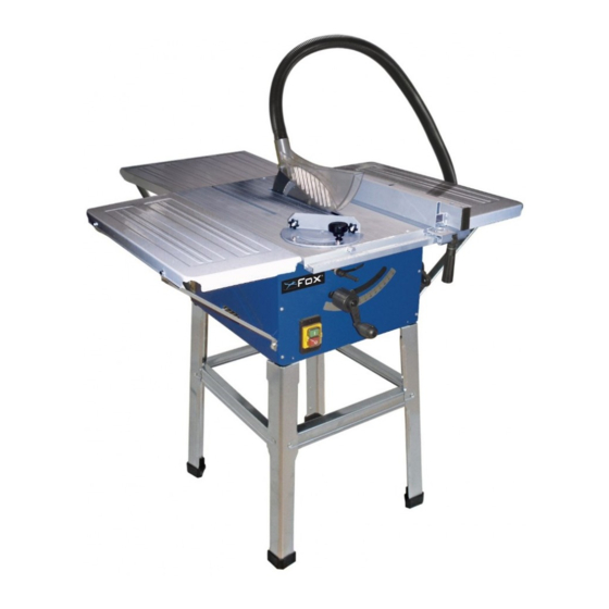
Page 1: Table Saw
TABLE SAW FOX Model F36-522C This machine must be connected to an external Dust Extraction Device. Failure to do so could result in damage to the motor and invalidation of the warranty... -
Page 2: Table Of Contents
Table saw FOX MODEL F36-522C TABLE OF CONTENTS Safety instructions…………………………………………………………………………………………… Page 3 Specific safety instructions for saws………………………………………………………………………. Page 5 Specifications………………………………………………………………………………………………… Page 8 Noise information……………………………………………………………………………………………. Page 8 Electrical connections………………………………………………………………………………………. Page 9 Earthing instructions………………………………………………………………………………………… Page 9 ... -
Page 3: Safety Instructions
ATTENTION : - Read the instructions for use carefully before using the machine - This device meets current safety standards for electrical machines. - Incorrect use may result in injury. Anyone not familiar with the instructions for use should not use the machine. - Page 4 8. Wear appropriate clothing. Avoid loose clothing, and remove jewellery which could become caught in moving parts. Non-slip shoes are particularly recommended when working outside. Keep long hair tied up. 9. Always wear safety glasses. Also wear a mask if operating the machine creates dust. 10.
-
Page 5: Specific Safety Instructions For Saws
SPECIFIC SAFETY INSTRUCTIONS FOR SAWS Do not use the saw until it is completely assembled and installed according to the instructions in this manual. If you are not completely familiar with operating saws, obtain help from a qualified person. Replace table insert when worn. Use only saw blades recommended by the manufacturer, which conform to EN 847-1. - Page 6 When working with a long workpiece, use an additional support such as a saw blade to prevent the blade from grabbing the work. When cutting round wood, use clamps that prevent the workpiece from turning on the table. There must be no nails or other foreign bodies in the part of the workpiece you want to cut. Never load the machine so much that it slows down and overheats.
- Page 7 Move the rip fence out of the way when crosscutting. Feed the work into the blade AGAINST the direction of rotation only. Never use the fence as a cut-off gauge when crosscutting. Keep these instructions safe.
-
Page 8: Specifications
SPECIFICATIONS Motor : 1500W – 240V (2hp) Blade diameter : 250mm Bore diameter : 30mm Speed : 5700rpm Max. cutting capacity at 90° : 75mm Max. cutting capacity at 45° : 60mm Dimensions (h x l x d) : 1100x444x625mm Dimensions inc extensions (h x l x d) : 1100x944x935mm Weight :... -
Page 9: Electrical Connections
ELECTRICAL CONNECTIONS EXTENSION CORDS Before using an extension cord, ensure the insulation is not cut or worn. Immediately repair or replace a damaged or frayed cord. Length of the extension cord: up to 15m Dimension of the wire: 3 x 2.5mm ATTENTION : Extension cords must be removed from the work area or located so that they will not get caught in parts, tools or other objects while using the tool. -
Page 10: Environmental Protection
ENVIRONMENTAL PROTECTION The crossed-out wheeled bin means that within the European Union the product must be taken to separate collection at the product end-of-life. This applies to your device but also to any enhancements marked with this symbol. Do not dispose of these products as unsorted municipal waste. -
Page 11: Recommended Use
RECOMMENDED USE This machine has been manufactured for longitudinal and cross cutting of wood and similar materials. The blade can be tilted from 0° to 45° and at 0° it can cut up to 73mm, while if the blade is tilted it can cut up to a width of 60mm. Do not cut wood wider than 73mm. - Page 12 To make the table saw work correctly, you must assemble the various parts. A detailed explanation of this follows. We recommend you read the assembly instructions carefully and follow them to the letter. Once you have assembled the table saw, in order to use it you must place it on a perfectly plane surface, in a covered, clean, empty and well- ventilated environment, with a medium level lighting.
-
Page 13: Machine Description And Photos
MACHINE DESCRIPTION AND PHOTOS 1. Workbench 18. Rip fence’s rail 2. Blade protection 19. Graduated plate of the rip fence 3. Pusher 20. Rip fence support 4. Blade 21. Rip fence profile 5. Riving knife 22. Rip fence lock knob 6. -
Page 17: Assembling The Base
ASSEMBLING THE BASE CAUTION : Before any adjustment, repair or maintenance work, and before changing the blade, switch off the machine and disconnect it from the power supply by removing the plug from the socket. 1. Remove the table saw from the package, turn it upside down and place it on the ground, as shown in Fig. 17, while protecting it so as not to damage it. -
Page 18: Assembling And Adjusting The Riving Knife And Blade Protection
ASSEMBLING AND ADJUSTING THE RIVING KNIFE AND BLADE PROTECTION 1. Unscrew the screw (Fig. 7, 34) and remove the bench insert (Fig. 7, 6). 2. Insert the riving knife (Fig 2, 5) between the two steel plates, by making the knife groove glive in the two joggles of the fixed plate, and move the mobile plate close by tightening the socket head screw by hand (Fig. -
Page 19: Assembling And Adjusting The Rip Fence
3. Loosen the blade clamping nut by placing a wrench on the nut and the other on the milling of the shaft, as shown in Fig. 5. 4. Caution : Turn the nut in the rotational direction of the blade. 5. -
Page 20: Assembling The Mitre Gauge
ASSEMBLING THE MITRE GAUGE You can use the mitre gauge to cut crosswise. 1. Insert the mitre gauge in the groove (Fig. 9, 49). 2. Loosen the knob (Fig. 9, 32), choose the desired angle and tighten the knob. 3. Keep the wood piece perfectly straight and proceed to cut. BLADE HEIGHT ADJUSTMENT HANDLE By turning the handle (Fig. -
Page 21: On/Off Switch
1. Loosen the knobs (Fig. 13, 26) and make the rip fence glide until its end is on the imaginary line mentioned above. 2. Tighten the two knobs firmly then proceed to cut. ON/OFF SWITCH WARNING : Before switching on the machine, ensure that the blade is correctly fitted, that there are no objects on the workbench and that the blade guard is assembled and working correctly. -
Page 22: Angle Crosscut
ANGLE CROSSCUT This means cutting or trimming the wood piece in the direction of the grain and must always be carried out using the rip fence, as shown in Figs. 21-22. You can cut longitudinally, as shown in Fig. 21, or longitudinally and tilted, with the blade tilted from 0°... -
Page 23: Cross Cut And Oblique Cut
CROSS CUT AND OBLIQUE CUT In order to carry out these kind of cuts you must use the mitre gauge and without the rip fence on the workbench. Cross cut consists in cutting the wood piece crosswise to the wood grain, with the goniometer at 0°, while during oblique cutting the mitre gauge is fixed at a different angle, as shown in Fig. -
Page 24: Maintenance
MAINTENANCE A composed cut is a combination between an angle and an oblique cut. The cut is carried out at an angle different from 90°, both compared to the workbench’s surface and to the workpiece’s length. CAUTION: Before making any adjustments, repair or maintenance work, and before changing the blade, switch off the machine and disconnect it from the power source by removing the plug from the socket. -
Page 25: Troubleshooting
TROUBLESHOOTING The saw does not start: The power socket is not supplying power correctly The power cable is faulty The motor is damaged or the carbon brushes must be replaced Machine vibrations: The inclination lock handle is not tightened ... -
Page 26: Parts Diagram
PARTS DIAGRAM... -
Page 27: Parts List
PARTS LIST... -
Page 28: Wiring Diagram
WIRING DIAGRAM... -
Page 29: Dart Tool Group Guarantee
Power Tools and accessories which, upon examination, prove to be defective in workmanship or material. The warranty period for the FOX branded products is one year for parts and labour and three years for parts only. The guarantee does not include repair, labour or parts requiring replacement because of misuse, abuse, or normal wear and tear. -
Page 30: Declaration Of Conformity
KIRKCALDY, UK, KY1 3PD Tel. +44 (0) 1592 652946 Fax: +44 (0) 1592 654854 Declares that the: TABLE SAW (F36-522C) is in compliance with the regulations included in the Directives: CEE 2006/42-2004/108-2006/95 Person authorized to create the technical file: Robert Paterson 06.05.2011...
Need help?
Do you have a question about the F36-522C and is the answer not in the manual?
Questions and answers