Table of Contents
Advertisement
Available languages
Available languages
Advertisement
Table of Contents

Related Manuals for Fox F36-522


Summary of Contents for Fox F36-522
- Page 1 BANCO SEGA 254 mm TABLE SAW 254 mm Modello Fox F36-522 Fox model F36-522...
- Page 2 SOMMARIO / INDEX ITALIANO (IT) 3÷26 Manuale originale, Original manual ENGLISH (EN) 27÷50 Manuale tradotto dall’originale / Manual translated from the original DICHIARAZIONE DI CONFORMITA / DECLARATION OF CONFORMITY ESPLOSO / EXPLODED VIEW SCHEMA ELETTRICO / WIRING DIAGRAM...
-
Page 3: Table Of Contents
Banco sega 254 mm (Modello F36-522) SOMMARIO • Sicurezza Pag. 4 • Regole generali di sicurezza Pag. 5 • Regole supplementari di sicurezza per le seghe circolari Pag. 7 • Protezione dell’ambiente Pag. 9 • Simboli Pag. 9 • Collegamento dell’ utensile alla corrente Pag. -
Page 4: Sicurezza
SICUREZZA ATTENZIONE: Quando si utilizzano utensili elettrici si dovrebbero sempre rispettare, oltre a quelle riportate in questo manuale, tutte le precauzioni base di sicurezza per ridurre il rischio di incendio, scossa elettrica e danni personali. Leggere attentamente tutte queste istruzioni prima di utilizzare questo prodotto e conservarle scrupolosamente. -
Page 5: Regole Generali Di Sicurezza
REGOLE GENERALI DI SICUREZZA 1. Mantenete l’area di lavoro pulita. Nelle zone o nei banchi di lavoro ingombri è più alta la probabilità di incidenti. 2. Evitate un ambiente pericoloso. Non esponete gli utensili alla pioggia e non utilizzateli in ambienti umidi o bagnati, per evitare i fenomeni di elettrolocuzione. Mantenete la zona di lavoro ben illuminata. - Page 6 16. Non forzate l’utensile. La lavorazione sarà migliore e maggiormente sicura se l’utensile viene utilizzato al ritmo per il quale è stato concepito. 17. Utilizzate l’utensile appropriato. Non forzate un piccolo utensile a fare il lavoro di un utensile a utilizzo intensivo. Per esempio, non utilizzate una sega circolare per tagliare dei rami o dei ceppi.
- Page 7 REGOLE DI SICUREZZA GENERALI PER LE SEGHE CIRCOLARI 1. NON AVVIATE la sega finché non è completamente assemblata e installata secondo le direttive del presente manuale. 2. UTILIZZATE sempre la protezione lama, il coltello divisore e lo spingipezzo per “tagliare completamente”.
- Page 8 15. NON UTILIZZATE mai dei solventi per pulire i pezzi in plastica. I solventi possono sciogliere o danneggiare il materiale. Utilizzate solamente uno straccio umido per pulire i pezzi in plastica. 16. INSTALLATE la sega in maniera PERMANENTE su una superficie in piano prima di utilizzarla.
-
Page 9: Protezione Dell'ambiente
PROTEZIONE DELL’AMBIENTE INFORMAZIONE AGLI UTENTI Ai sensi dell’art.13 del Decreto Legislativo 25 luglio 2005, n.151 “Attuazione delle Direttive 2002/95/CE, 2002/96/CE, e 2003/108/CE, relative alla riduzione dell’uso di sostanze pericolose nelle apparecchiature elettriche ed elettroniche, nonché allo smaltimento dei rifiuti”, si precisa quanto segue: •... -
Page 10: Collegamento Dell'utensile Alla Corrente
Matricola/anno di costruzione COLLEGAMENTO DELL’UTENSILE ALLA CORRENTE ALLACCIAMENTO ELETTRICO Per l’alimentazione della vostra macchina è necessaria una tensione alternata a 230 V 50 Hz con conduttore di terra. Assicuratevi che la vostra alimentazione abbia queste caratteristiche, che sia protetta da un interruttore differenziale e magnetotermico e che l’impianto di terra sia efficiente. -
Page 11: Uso Conforme Alle Norme
assicuratevi di utilizzare una prolunga di dimensioni sufficienti per trasportare la corrente di cui l’utensile ha bisogno. Una prolunga sotto dimensionata provocherebbe una caduta di tensione elevata nella linea, con perdita di potenza e conseguente surriscaldamento del motore. Possono essere utilizzate solamente delle prolunghe conformi alle norme CE . Lunghezza della prolunga elettrica: fino a 15 m Dimensioni del cavo: 3 x 2,5 mm²... -
Page 12: Caratteristiche Tecniche
CARATTERISTICHE TECNICHE Potenza motore: 1500 W Tensione di alimentazione e frequenza: 230 V - 50 Hz Tipo di servizio: continuo Diametro della lama: 254 mm Spessore del corpo lama montato: 1,8 mm Larghezza di taglio lama montata : 2,8 mm Diametro del foro della lama: 30 mm Velocità... -
Page 13: Disimballo
DISIMBALLO Nell’imballo della sega sono presenti: 1. Un banco sega 2. Un goniometro 3. Una guida parallela 4. Uno spingipezzo 5. Due estensioni del piano di lavoro 6. Quattro barre di attacco delle estensioni del piano di lavoro 7. Due binari per il fissaggio della guida parallela 8. -
Page 14: Descrizione Del Banco Sega
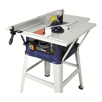
DESCRIZIONE DEL BANCO SEGA Interruttore avvio / arresto Ghiera di inclinazione della lama Pomello di bloccaggio della lama Spingipezzo Goniometro Lama Coltello divisorio Protezione della lama Guida parallela 10. Impugnatura di regolazione e di bloccaggio della guida parallela Manovella di salita e discesa... -
Page 15: Montaggio Del Basamento
MONTAGGIO DEL BASAMENTO 1. Prendete l’insieme del basamento nell’imballaggio. 2. Assemblate due piedi con la traversa utilizzando le viti e i dadi forniti (Fig. 2). 3. Assemblate gli altri due piedi con la seconda traversa (Fig. 3). 4. In seguito posizionate queste due sotto-unità e assemblate le ultime due traverse in modo da formare un quadrato. -
Page 16: Montaggio Della Manovella Di Salita-Discesa Ed Inclinazione Della Lama
9. In seguito rifissate la piastra con le 4 viti fornite. 10. Posizionate i 4 piedi precedentemente assemblati con le traverse sul fondo della sega circolare. 11. Utilizzate le viti e i dadi per fissare solidamente la sega al basamento. Ogni piede è sostenuto da 4 viti e dadi. -
Page 17: Montaggio Del Coltello Divisore
Inserto tavola 5) Fare girare la lama a mano per verificare che non ci siano interferenze. 6) Collegate la macchina e avviatela un istante senza utilizzarla direttamente con il materiale da tagliare, per verificare che non ci sia nessun problema. PERICOLO: SOSTITUITE L’INSERTO DELLA TAVOLA SE ROVINATO O TAGLIATO MONTAGGIO DEL COLTELLO DIVISORE AVVERTENZA: Spegnete l’interruttore e scollegate la sega dalla corrente, togliendo la spina... -
Page 18: Assemblaggio Delle Estensioni Del Piano Di Lavoro
ASSEMBLAGGIO DELLE ESTENSIONI DEL PIANO DI LAVORO Allineate i tre fori di ogni estensione con i tre fori del piano di lavoro su una delle parti laterali del piano (Fig. 13, 14, 15 e 16). Utilizzate le sei viti e dadi M6 x 15 per fissare queste due estensioni. Per montare i quattro supporti delle estensioni, utilizzate le 8 viti M6x15, le rondelle di arresto M6 e i dadi corrispondenti, così... -
Page 19: Montaggio Della Guida Parallela
MONTAGGIO DELLA GUIDA PARALLELA Montate la guida parallela in modo che il lato con l’indicatore sia dalla parte destra. (Fig. 17). Prima di tutto, allentate completamente la manopola di bloccaggio della guida, poi montate la parte frontale della guida parallela in modo che questa sia in contatto con la parte frontale del piano di lavoro, successivamente montate la parte posteriore della guida in modo che la guida sia a livello con la tavola. -
Page 20: Avvio Del Banco Sega
AVVIO DEL BANCO SEGA PERICOLO: Prima avviare macchina assicuratevi che non ci sia nessun oggetto sul piano di lavoro, che il coltello divisore sia ben posizionato e che la protezione della lama sia montata, integra e perfettamente funzionante. Premete il pulsante ON (verde) per avviare la macchina (Fig. -
Page 21: Manovella Di Salita E Discesa Della Lama
MANOVELLA DI DISCESA/SALITA DELLA LAMA Questa manovella serve a far salire e scendere la lama. Ruotatela in senso orario per far scendere la lama e in senso antiorario per farla risalire (Fig. 20). Manovella salita/discesa GHIERA DI INCLINAZIONE DELLA LAMA Ghiera inclinazione lama Questa ghiera serve a far inclinare la lama (Fig. -
Page 22: Taglio Trasversale
TAGLIO TRASVERSALE Tagliare trasversalmente consiste nel tagliare perpendicolarmente al senso delle fibre del legno (Fig. 23). Per il taglio trasversale, utilizzate il goniometro a 0°. Prima di utilizzare il goniometro, assicuratevi bloccato sull’angolo desiderato. Questa guida può essere utilizzata in una della scanalature del piano di lavoro. -
Page 23: Taglio Composto
TAGLIO COMPOSTO Il taglio composto è la combinazione di un taglio inclinato ed obliquo. Il taglio viene realizzato ad un angolo diverso da 90° sia rispetto alla superficie di riferimento del piano di lavoro che rispetto alla lunghezza del pezzo (Fig. 26). UTILIZZO DELLA GUIDA PARALLELA Il lavoro di rifilatura consiste nel tagliare il legno nel senso delle fibre. -
Page 24: Rifilatura Inclinata
RIFILATURA INCLINATA Per rifilare degli spessori di larghezza inferiore o uguale a 150 mm, utilizzate la guida parallela solo a destra della lama e utilizzate lo spingipezzo per spingere il pezzo fino a che questo non sia completamente tagliato (Fig. 28). ASPIRAZIONE DELLE POLVERI Collegare l’aspiratore sull’uscita posteriore della macchina. -
Page 25: Anomalie Di Funzionamento
Verificare l’integrità del cavo di alimentazione. Verificare il gioco degli ingranaggi e se riscontrato eccessivo farli sostituire da un centro assistenza. CONTROLLO E SOSTITUZIONE DELLE SPAZZOLE DEL MOTORE 1. Scollegate la macchina dalla presa di corrente. 2. Capovolgete la macchina su un pezzo di cartone. 3. - Page 26 ASSISTENZA Tutti gli utensili e accessori Fox sono costruiti e controllati utilizzando le più moderne e sicure tecniche produttive. Se nonostante queste attenzioni un utensile dovesse guastarsi la riparazione deve essere fatta da un centro riparazioni autorizzato Delta France. L’elenco dei centri assistenza è reperibile presso i vari punti vendita o telefonando a 051/6946469 o inviando una richiesta all’...
- Page 27 Table saw 254 mm (Fox model F36-522) INDEX • Safety instructions • General safety instructions • Specific safety instructions for circular saws • Environment protection • Symbols • Electrical connections • Recommended use • Technical specifications • Noise conditions • Removal of package •...
- Page 28 SAFETY INSTRUCTIONS CAUTION: Besides following the instructions mentioned in this manual, when using electric equipment you must always observe all safety precautions to prevent risk of fire, electric shock and personal injury. Read this instruction manual before use and keep it carefully. Working with an electric machine can be dangerous if you do not follow suitable safety measures.
- Page 29 40. Do not force the machine. You can obtain better and safer results if you use the machine at the cutting pressure for which it has been designed. 41. Use the suitable tool. Do not use a small tool for an intensive job. Fox example, do not use a circular saw to cut branches or stumps.
- Page 30 42. Block the piece. If possible, use C-clamps or a holder to fix the piece. It is safer than using only your hands. 43. Keep the tools in perfect conditions. Keep the tools sharp and clean to obtain better and safer results.
- Page 31 SPECIFIC SAFETY RULES FOR CIRCULAR SAWS 26. DO NOT start the saw until it is assembled and installed according to the instructions of this manual. 27. ALWAYS USE the protective cap, the riving knife and the clamping device in order to cut the piece completely.
- Page 32 40. NEVER USE thinners to clean the plastic pieces of the machine. Thinners can melt or damage the material. Only use a damp cloth for cleaning plastic workpieces. 41. INSTALL the saw PERMANENTLY on a plane surface before using it. 42.
- Page 33 ENVIRONMENT PROTECTION INFORMATION FOR USERS In accordance with art. 13 of Legislative Decree 25th July 2005, no. 151 “Implementation of Directives 2002/95/EEC, 2002/96/EEC and 2003/108/EEC, relative to reducing the use of hazardous substances in electric and electronic appliances and the disposal of waste”, please take note of the following: •...
- Page 34 ELECTRICAL CONNECTIONS ELECTRICAL CONNECTIONS Use 230 V 50 Hz alternate voltage equipped with a earthing conductor to supply your machine. Ensure that the power supply corresponds to this voltage, that it is protected by a differential and magnetothermal switch, and that the earthing system is efficient. If your machine does not work when connected to a socket, check carefully the power supply features.
- Page 35 Before using any kind of extension lead, check ther are not bare wires and that the insulation is not cut or worn. Repair and change immediately it if it is damaged or worn. WARNING: Extension lead must be arranged away from the working area in order that they do not get in touch with the workpieces, the tool or other parts of the machine, thus creating possible risks.
- Page 36 TECHNICAL SPECIFICATIONS Engine capacity: 1500 W Voltage and frequency: 230 V - 50 Hz Operation: continuous Saw blade’s diameter: 254 mm Blade width when assembled: 1,8 mm Cutting width when the blade is assembled: 2,8 mm Bore diameter: 30 mm Rotational speed: 4500 RPM Riving knife and groove’s width:...
- Page 37 REMOVAL OF PACKAGE In the package there are: 1. Table saw 2. Goniometer 3. Rip fence 4. Pusher 5. Two workbench extensions 6. Four attach bars for workbench extensions 7. Two fixing rails for the rip fence 8. Screws for fixing wokbench extensions and rails 9.
- Page 38 MACHINE DESCRIPTION 12. ON / OFF switch 13. Angle ferrule of the saw blade 14. Locking knob of the saw blade 15. Pusher 16. Goniometer 17. Saw blade 18. Riving knife 19. Saw blade protection 20. Rip fence 21. Rip fence’s adjustment and locking handle 22.
- Page 39 ASSEMBLY OF THE BASE 12. Take all the parts of the base from the package. 13. Assemble two feet with the crossbar by using the screws and nuts provided (Fig. 2). 14. Assemble the other two feet with the second crossbar (Fig. 3). 15.
- Page 40 20. Then fix again the plate with the four screws provided in the package. 21. Place the four feet which you have previously assembled with the crossbars in the bottom of the circular saw. 22. Use the screws and the nuts to firmly fix the saw to the base. Each foot is supported by 4 screws and nuts.
- Page 41 Bench insert 11) Make the blade turn by hand to check if there are some obstacles. 12) Connect the machine and start it for a while without using it with the material to be cut, in order to check that there is not any problem. DANGER: REPLACE THE BENCH INSERT IF IT IS WORN OR CUT ASSEMBLY OF THE RIVING KNIFE CAUTION: Before any adjustment, repair or maintenance work, and before changing the...
- Page 42 ASSEMBLY OF WORKBENCH EXTENSIONS Align the three holes of each extensions with the three holes of the workbench on one of the lateral sides of the workbench (Fig. 13, 14, 15 e 16). Use the six screws and nuts M6 x 15 to fix these two extensions. To assemble the four bearings of the extensions, use 8 screws M6x15, the lock washers M6, the corresponding nuts, and the 16 washers.
- Page 43 ASSEMBLY OF THE RIP FENCE Assemble the rip fence in order that the side with the pointer is on the right side (Fig. 17). First loosen completely the fence’s lock handle, then assemble the front side of the rip fence in order that it is in contact with the front side of the workbench, then assemble the back side of the fence in order that it is at workbench level.
- Page 44 START OF THE TABLE SAW WARNING: Before switching on the machine be sure that there is not any object on the workbench, that the riving knife is correctly placed and that the protective cap and that the blade is assembled, is not damaged and works perfectly.
- Page 45 HEIGHT ADJUSTMENT HANDLE You can use this handle to lift and lower the saw blade. Turn it clockwise to lower the saw blade and anti-clockwise to lift it (Fig. 20). Height adjustment handle ANGLE ADJUSTMENT FERRULE Angle adjustment ferrule You can use this ferrule to angle the saw blade (Fig. 21). Loosen the lock knob and then turn it clockwise to angle the saw blade to the left.
- Page 46 CROSSCUT Cross cutting means cutting perpendicularly to wood fibres’ direction (Fig. 23). To cross cut, use the goniometer at 0°. Before using it, be sure that it is locked on the desired angle. This guide can be used on one of workbench’s grooves.
- Page 47 COMPOSED CUTTING Composed cut is a combination between an angle and a mitre cut. The cut is carried out at an angle different from 90° both from workbench’s surface and from the workpiece’s length (Fig. 26). USE OF THE RIP FENCE Cropping consists in cutting the wood along the fibres.
- Page 48 ANGLE CROPPING To trim pieces which are less than 150 mm wide, use the rip fence only on the right side of the blade and use the pusher to push the piece until it is completely cut (Fig. 28). DUST EXHAUSTION Connect the dust-collection device to the back output of the machine.
- Page 49 Check the saw blade brake time, and if it is longer than 10 seconds take the machine to an after sales service. Check the noise of the engine and the consumption of the carbon brushes periodically. Check that the supply cable is not damaged. Check the play of the gears and if is it excessive get them replaced by an after sales centre.
- Page 50 All the tools and accessories are made and tested by using the safest and most modern productive methods. However, if a tool get damaged, it must be repaired by an authorised after sales centre. You can call the phone number 051/6946469 or by sending a request to the e-mail address info@fox-machines.com...
- Page 51 DICHIARAZIONE DI CONFORMITA’ CE DEL COSTRUTTORE Femi SpA Via Salieri 33/35 – 40024 - Castel S.Pietro Terme (BO) Italia Tel. +39 051 6946469 - Fax +39 051 6946470 Dichiara che il: BANCO SEGA (F36/522) è conforme alle disposizioni contenute nelle Direttive: (CEE 98/37) CEE 2006/42-2004/108-2006/95 CE DECLARATION OF CONFORMITY OF THE MANUFACTURER Femi SpA Via Salieri 33/35 –...
- Page 52 F36-522 BANCO SEGA 254MM / TABLE SAW 254 MM...
- Page 53 F36-522 BANCO SEGA 254MM / TABLE SAW 254 MM Art. / Item Art. / Item F36522-1 F36522-44 F36522-2 F36522-45 F36522-3 F36522-46 F36522-4 F36522-47 F36522-5 F36522-48 F36522-6 F36522-49 F36522-7 F36522-50 F36522-8 F36522-51 F36522-9 F36522-52 F36522-10 F36522-53 F36522-11 F36522-54 F36522-12 F36522-55 F36522-13...
- Page 54 F36-522 BANCO SEGA 254MM / TABLE SAW 254 MM Art. / Item Art. / Item F36522-87 F36522-132 F36522-88 F36522-133 F36522-89 F36522-134 F36522-90 F36522-135 F36522-91 F36522-136 F36522-92 F36522-137 F36522-93 F36522-138 F36522-94 F36522-139 F36522-95 F36522-140 F36522-96 F36522-141 F36522-97 F36522-142 F36522-98 F36522-143 F36522-99...
-
Page 55: Schema Elettrico / Wiring Diagram
SCHEMA ELETTRICO / WIRING DIAGRAM...
Need help?
Do you have a question about the F36-522 and is the answer not in the manual?
Questions and answers