
Related Manuals for Eneo AK-5 Callisto dome series


Summary of Contents for Eneo AK-5 Callisto dome series
- Page 1 Installation Guide Camera junction box for Callisto dome series AK-5...
-
Page 2: Table Of Contents
Inhalt Inhalt ............................2 Sicherheitshinweise ........................3 Lieferumfang ..........................3 Produktbeschreibung und Anschlüsse ................3 Installation ..........................4 Anschlüsse ..........................5 Verkabelung durch seitliche Kabelverschraubung ..........5 Verkabelung durch Kabeltüllen im Boden ..............5 Verwendung des Steckverbinders .................6 Verkabelungsanleitung ......................6 Kabelorganisation für Analog / HDcctv Kameras ...........6 Kabelorganisation für IP Kameras .................7 Signalbelegung ......................7 Weitere Informationen ......................8... -
Page 3: Sicherheitshinweise
Sicherheitshinweise Bitte beachten Sie auch die beiliegenden Sicherheitshinweise und lesen Sie diese Anleitung vor Inbetriebnahme sorgfältig durch. Wichtige Hinweise sind mit einem Achtungsymbol gekennzeichnet. Lieferumfang • 1x Anschlussbox • 1x Installations- und Betriebsanleitung • 1x Inbusschlüssel • 3x Kunststoffdübel 6x30mm •... -
Page 4: Installation
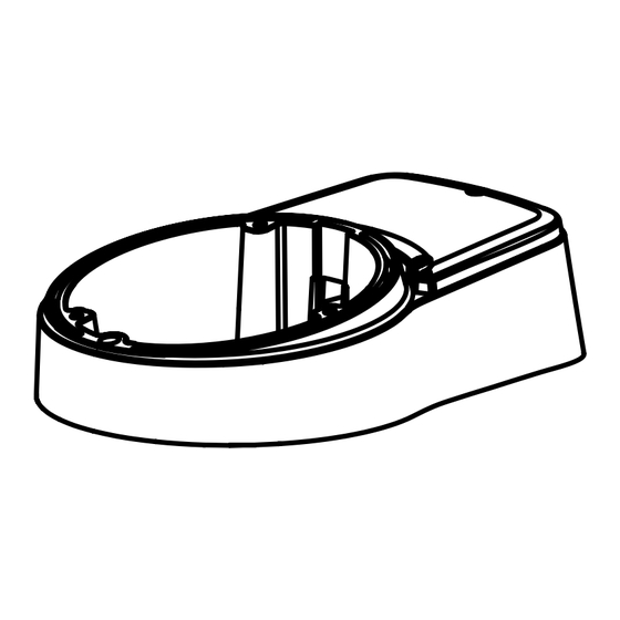
Technische Daten Aluminum Druckguss Material: Oberfläche: Hellgrau spritzlackiert Umgebung: Innen-/Außenbereich für Callisto Dome Gewicht: 1,3kg Schutzart: IP66 229.85 Installation Anschlussbox Abdeckung Keiladapter Inbusschlüssel... -
Page 5: Anschlüsse
1. Halten Sie die Bohrschablone an die Installationsstelle und bohren Sie die Lö- cher in Decke oder Wand, falls erforderlich. 2. Setzen Sie die Anschlussbox an die Stelle mit den vorgebohrten Löchern und befestigen Sie sie mit den Montageschrauben durch die Montagelöcher (3x). 3. -
Page 6: Verwendung Des Steckverbinders
Verwendung des Steckverbinders Steckverbinderabdeckung Spannungsver- sorgungskabel Ethernet Kabel 1. Richten Sie die Kabeldrähte am Steckverbinder aus. Dann drücken Sie die Steckverbinderabdeckung wie dargestellt fest. 2. Organisieren Sie die verbundenen Kabel in der Anschlussbox. Verkabelungsanleitung Kabelorganisation für Analog / HDcctv Kameras ①... -
Page 7: Kabelorganisation Für Ip Kameras
Kabelorganisation für IP Kameras ① Die Kabel an der Domebasis sind gelöst. ② Demontieren Sie die Kopplerplatine für die LAN Verkabelung. ③ Verbinden Sie die Ethernet- und Spannungsversorgungskabel mit den jeweiligen Anschlüssen. Signalbelegung ~24V / 12VDC ~24V / GND Alarm-Ein Alarm-Aus Audio-In Audio-Out... -
Page 8: Weitere Informationen
Weitere Informationen Weitere Sprachversionen dieser Anleitung sind auf der eneo Website unter www.eneo-security.com verfügbar. -
Page 9: Contents
Contents Contents ...........................9 Notes on safety ........................10 Scope of delivery ......................... 10 Product description and connections ................10 Installation ..........................11 Cable connections ....................... 12 Cable through with the gland on the side ............12 Cable through with the grommets on the bottom ..........12 Using the modular jack connection ..............13 Cabling instruction ....................... -
Page 10: Notes On Safety
Notes on safety Please also pay attention to the enclosed safety instructions, and carefully read through this instruction guide before initial operation. Important points of advice are marked with a caution symbol. Scope of delivery • 1x Mount adaptor • 1x Installation and Operating Instruc- tions •... -
Page 11: Installation
Technical specifications Aluminum die-casting Construction: Finish: Light-gray spray Environment: Indoor/Outdoor for a Callisto dome Weight: 1.3kg Protection: IP66 229.85 Installation Junction box part Tilted surface mount Cover part L-Wrench... -
Page 12: Cable Connections
1. Locate the mounting template at the installation position and drill the ceiling or wall if needed. 2. Place junction box part on pre-drilled position and fix it through mount holes (x3) by using mount screws. 3. Route the dome cable to the junction part and attach the dome to the surface mount part using assembly screws as shown. -
Page 13: Using The Modular Jack Connection
Using the modular jack connection Modular jack cover Power source cable Ethernet cable 1. Align the cable wires on the modular jack. Then push down the modular jack cover as illustrated. 2. Organize the connected cables in the junction box part. Cabling instruction Cable assembling for Analog / HDcctv cameras ①... -
Page 14: Cable Assembling For Ip Cameras
Cable assembling for IP cameras ① Cables are unfixed on the Dome base. ② Disassemble coupler board for LAN cabling. ③ Connect the ethernet and power cables to their repective connections. Signal assignment ~24V / DC12V ~24V / GND Alarm-In Alarm-Out Audio-In Audio-Out... -
Page 15: Further Information
Further information Further language versions of this manual are available from the eneo web site at www.eneo-security.com... -
Page 16: Sommaire
Sommaire Sommaire ..........................16 Consignes de sécurité ......................17 Contenu de la livraison ....................... 17 Description du produit avec ses raccordements ............17 Installation ..........................18 Connexions de câbles ......................19 Câble passant au travers du presse-étoupe sur le côté ........19 Câble passant au travers des œillets au dos du boîtier ........19 Connexion de la prise modulaire .................20 Instructions de câblage ...................... -
Page 17: Consignes De Sécurité
Consignes de sécurité Avant toute utilisation, veuillez respecter les consignes de sécurité mentionnées ci- après et lire attentivement cette notice. Les points importants sont précédés d´un symbole d´avertissement. Contenu de la livraison • 1x Adaptateur de montage • 1x Instructions d'installation et d'utili- sation •... -
Page 18: Installation
Spécifications techniques Aluminium coulé sous pression Structure : Finition : Gris clair Environnement : Intérieur/extérieur pour dôme Callisto Poids : 1,3 kg Protection : IP66 229.85 Installation Boîtier de connexion Support de montage Couvercle incliné Clé coudée... -
Page 19: Connexions De Câbles
Posez le gabarit de montage à la position de montage et faites un trou dans le pla- fond ou dans le mur si nécessaire. Placez le boîtier de connexion sur la position pré-forée, puis fixez-le à l'aide des vis de montage dans les trous de montage (x3). -
Page 20: Connexion De La Prise Modulaire
Connexion de la prise modulaire Cache de la prise modulaire Câble de source d'alimentation Câble Ethernet 1. Alignez les fils de câblage sur la prise modulaire. Mettez le cache sur la prise modulaire, comme illustré. 2. Organisez les câbles connectés dans le boîtier de connexion. -
Page 21: Raccordement Des Câbles Pour Les Caméras Ip
Raccordement des câbles pour les caméras IP ① Les câbles ne sont pas fixés sur la base du dôme. ② Démontez la carte de couplage pour le câblage LAN. ③ Branchez les câbles Ethernet et les câbles d'alimentation à leurs raccords res- pectifs. -
Page 22: Complément D'information
Complément d'information Ce manuel est disponible en d'autres langues sur le site Web d'eneo à l'adresse www.eneo-security.com... -
Page 23: Spis Treści
Spis treści Spis treści ..........................23 Wskazówki dotyczące bezpieczeństwa ................24 Elementy wchodzące w skład dostawy ................24 Opis produktu i połączeń ....................24 Instalacja ..........................25 Podłączenia przewodów ..................... 26 Kabel poprowadzony przez dławik na boku ............26 Kabel poprowadzony przez otwory na spodzie ............26 Połączenie z użyciem wtyku modułowego ............27 Instrukcja montażu okablowania .................. -
Page 24: Wskazówki Dotyczące Bezpieczeństwa
Wskazówki dotyczące bezpieczeństwa Prosimy przestrzegać także załączonych wskazówek dotyczących bezpieczeństwa i dokładnie przeczytać niniejszą instrukcję obsługi przed uruchomieniem urządzenia. Ważne wskazówki są oznaczone symbolem 'UWAGA'. Elementy wchodzące w skład dostawy • 1x adapter montażowy • 1x instrukcja instalacji i obsługi •... -
Page 25: Instalacja
Specyfikacje techniczne Aluminiowe poszycie Budowa: Wykończenie: Malowanie ciemnoszare Warunki otoczenia: Wewnętrzna/Zewnętrzna w przypadku kopułek Callisto Waga: 1.3kg Klasa ochrony: IP66 229.85 Instalacja Element puszki połączeniowej Element do montażu na Osłona pochylonej powierzchni Klucz imbusowy... -
Page 26: Podłączenia Przewodów
Umieść szablon montażowy w miejscu instalacji kamery a następnie wywierć odpo- wiednio dziury w ścianie lub suficie w razie potrzeby. Umieść element puszki połączeniowej w miejscu gdzie wywiercono otwory, a następ- nie przykręć ją, korzystając z otworów montażowych (x3) oraz dołączonych śrub. Poprowadź... -
Page 27: Połączenie Z Użyciem Wtyku Modułowego
Połączenie z użyciem wtyku modułowego Pokrywa złącza modułowego Przewód zasilający Przewód ethernetowy 1. Wyrównaj przewody we wtyku modu- larnym. Zaciśnij pokrywę wtyczki jak na rysunku. 2. Uporządkuj podłączone przewody w puszce połączeniowej. Instrukcja montażu okablowania Przygotowanie okablowania w kamerach analogowych / HDcctv ①... -
Page 28: Przygotowanie Okablowania W Kamerach Ip
Przygotowanie okablowania w kamerach IP ① Przewody nie są przytwierdzone do podstawy kopułki.. ② Zdemontuj płytkę połączeniową przeznaczoną do okablowania LAN. ③ Podłącz przewody ethernetowe i zasilania do odpowiednich złącz. Oznaczenie sygnałów ~24V / DC12V ~24V / GND Wejście alarmowe Wyjścia alarmowe Masa Wyjście audio... -
Page 29: Informacje Dodatkowe
Informacje dodatkowe Inne wersje językowe niniejszej instrukcji są dostępne na stronie internetowej www.eneo-security.com... -
Page 30: Содержание
Содержание Содержание ......................... 30 Замечания по безопасности ................... 31 Объем поставки ........................31 Описание изделия и подключения ................31 Монтаж ..........................32 Соединения .......................... 33 Соединение через боковое отверстие и кабельный сальник ......33 Соединение через защитные колпачки в основании коробки......33 С... -
Page 31: Замечания По Безопасности
Замечания по безопасности Обратите, пожалуйста, внимание на прилагаемые указания по безопасности и внимательно прочитайте это руководство перед началом работы. Важные рекомендации отмечены символом предостережения. Объем поставки • 1х Соединительная коробка • 1x Инструкция по монтажу и эксплу- атации • 1х Шестигранный ключ •... -
Page 32: Монтаж
Технические спецификации Конструкция: Литой под давлением алюминий Полировка: Светло-серое напыление Применение: Внутреннее/Уличное для купольных камер серии Callisto Вес: 1.3 кг Защита: IP66 229.85 Монтаж Часть соединительной коробки Наклонная монтажная Крышка часть Шестигранный ключ... -
Page 33: Соединения
1. Приложите монтажный шаблон к месту установки и, при необходимости, просверлите монтажные отверстия на стене или в потолке. 2. Прислоните соединительную коробку к предварительно просверленным отверстиям и закрепите её посредством винтового соединения крепёжных винтов с отверстиями для поверхностного монтажа (x3). 3. -
Page 34: С Применением Соединений Модульного Разъёма
С применением соединений модульного разъёма Крышка модульного разъёма Кабель элек- тропитания Кабель Ethernet 1. Распределите провода в правиль- ном порядке в модульном разъ- ёме. Затем закройте модульный разъём крышками, как показано на рисунке. 2. Спрячьте соединенные кабели в соединительной части коробки. Порядок... -
Page 35: Подключение Сетевых Видеокамер
Подключение сетевых видеокамер ① Освободите соединительный кабель на основании купольной камеры. ② Открутите соединительную плату сетевого подключения. ③ Соедините кабели Ethernet и электропитания соответствующим образом. Схема сигналов ~24 В / 12 В ~24 В / Заземление Тревожный вход Тревожный выход Заземление... -
Page 36: Дополнительная Информация
Дополнительная информация Данное руководство доступно на других языках на нашем веб-сайте www.eneo-security.com. - Page 40 VIDEOR E. Hartig GmbH Exclusive distribution through spe- cialised trade channels only. VIDEOR E. Hartig GmbH Carl-Zeiss-Straße 8 · 63322 Röder- mark/Germany Tel. +49 (0) 6074 / 888-0 · Fax +49 Technical changes reserved (0) 6074 / 888-100 www.videor.com...
Need help?
Do you have a question about the AK-5 Callisto dome series and is the answer not in the manual?
Questions and answers