Table of Contents
Advertisement
Quick Links
. . . . . . . . . . . . . . . . . . . . . . . . . . . . . . .
STT20000A
. . . . . . . . . . . . . . . . . . . . . . . . . . . . . . .
ATAPI Minicartridge Drive
. . . . . . . . . . . . . . . . . . . . . . . . . . . . . . .
. . . . . . . . . . . . . . . . . . . . . . . . . . . . . . .
. . . . . . . . . . . . . . . . . . . . . . . . . . . . . . .
Product Manual
. . . . . . . . . . . . . . . . . . . . . . . . . . . . . . .
Advertisement
Table of Contents

Related Manuals for Seagate STT20000A


Summary of Contents for Seagate STT20000A
- Page 1 ....... STT20000A .......
- Page 2 © 1998 Seagate Technology, Inc. All rights reserved No part of this publication may be reproduced in any form without written permission from Seagate Technology, Inc. Publication Number 10005136-001 , March 1998 Seagate, Seagate Technology, the Seagate logo and Sidewinder are trademarks or registered trademarks of Seagate Technology, Inc.
-
Page 3: Fcc Notice
Changes or modifications made to this equipment which have not been expressly approved Caution. by Seagate Technology may cause radio and television interference problems that could void the user's authority to operate the equipment. Further, this equipment complies with the limits for a Class B digital apparatus in accordance with Canadian Radio Interference Regulations. - Page 4 Seagate Technology provides this manual "as is," without warranty of any kind, either expressed or implied, including, but not limited to, the implied warranties of merchantability and fitness for a particular purpose. Seagate Technology reserves the right to change, without notification, the specifications contained in this manual.
-
Page 5: Table Of Contents
Installing the drive....................17 Mounting dimensions .................... 18 ATA-2 Interface pin assignments ................20 Drive operation and maintenance Introduction......................23 Front panel LED....................23 Using Travan cartridges ..................24 Loading and unloading cartridges ..............24 STT20000A Product Manual Page v... - Page 6 Table of Contents Setting the write–protect switch ..............25 Loading revised firmware via Seagate firmware cartridge ........26 Drive maintenance ....................27 Caring for tape cartridges ................27 Cleaning the drive read/write head..............27 Troubleshooting ....................28 ATAPI interface Introduction......................31 ATA-2 Interface ....................
- Page 7 Mechanics ...................... 72 Cartridge-load mechanism ................72 Capstan/drive-motor assembly ............... 72 Chassis ......................72 Control circuits ...................... 72 Head design ......................73 Flash EEPROM ....................73 Sensors and switches ................... 73 Drive media (Travan minicartridges)..............74 STT20000A Product Manual Page vii...
- Page 8 Table of Contents Glossary Acronyms and measurements Acronyms and abbreviations ................. 78 Units of measurement................... 80 Page viii STT20000A Product Manual...
-
Page 9: Introduction
Chapter 1 Introduction Drive overview The Seagate STT20000A extends the Seagate family of one-inch high, DC2000 drives that feature high performance, high reliability, and quiet operation. The drive transfers data at up to 60 megabytes per minute (Mbytes/min) without compression. - Page 10 With the availability of greater capacity disk drives and the growth of small networks, the need for cost-effective, high-capacity storage has grown. The STT20000A is ideal for high-end standalone computers, workstations, and small networks. Built using long-wearing materials and custom Large Scale Integration (LSI) components, the ATAPI drive was engineered for heavy-duty computer applications.
-
Page 11: Features
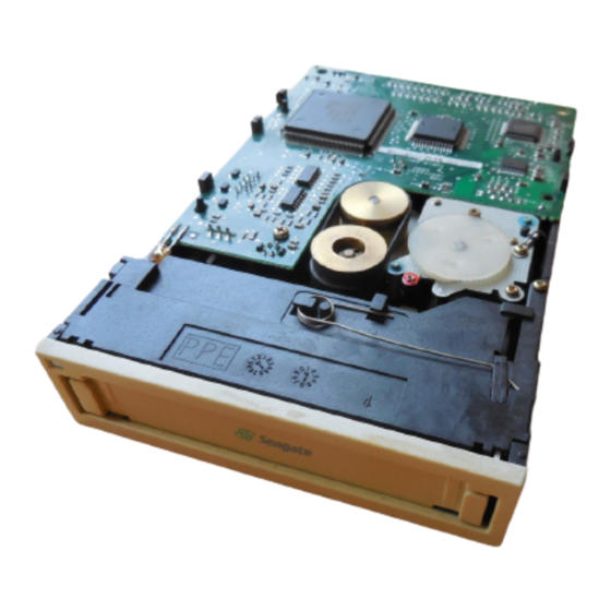
Figure 1-2 Internal STT20000A with mounting brackets Features The STT20000A embodies Seagate 's commitment to engineer reliable and durable tape drive products. Key features of the drive are as follows: • Internal form factor for installation in a 5.25-inch half-high or 3.5-inch by one- inch space •... -
Page 12: Typical System Configurations
(QIC-24, 1982) to the to the 20 Gbyte capacity achievable with the STT20000A minicartridge drive on a single Travan TR-5 cartridge. The streaming-tape intelligence in the STT20000A provides a continuous tape motion with an uninterrupted, precisely coordinated flow of data to and from the minicartridge. -
Page 13: Flash Eeprom
Software The STT20000A is a cost-effective means of backing up fixed disks. The drive is compatible with DOS version 5.0 or later, Microsoft Windows 3.1 or later,... -
Page 14: About This Manual
Theory of operation Details the functional operation of various assemblies of the ATAPI drive. Appendix A Glossary Defines key terms. Appendix B Acronyms and Lists the acronyms and measurements used in the measurements manual. Page 6 STT20000A Product Manual... -
Page 15: Specifications
6.51 in/165.5 mm Weight 1.0 lbs/0.5 kg 1.5 lbs/0.7 kg Figures 2-1 and 2-2 show the general dimensions of the STT20000A in 3.5-inch configuration (without mounting brackets) and in the 5.25-inch configuration (with mounting brackets). STT20000A Product Manual Page 7... - Page 16 Chapter 2 Specifications Figure 2-1 STT20000A (3.5-Inch mount) general dimensions 4.00 in (101.6 mm) 6.36 in (161.5 mm) 0.157 in (4 mm) 4.00 in (101.6 mm) 1.00 in (25.4 mm) Figure 2-2 STT20000A (5.25-Inch mount) general dimensions 0.86" (21.8mm) 5.49" (139.4mm) 5.76"...
-
Page 17: Power Specifications
Specifications Chapter 2 Power specifications The following table lists the power specifications for the STT20000A. (Power specifications are measured at the tape drive power connector and are nominal values.) Specification Measurement DC Voltage +12 VDC +5 VDC Voltage Tolerance ± 10% ±... -
Page 18: Performance Specifications
Chapter 2 Specifications Performance specifications The following table lists the performance specifications for the STT20000A. Feature Specification Capacity 10.0 gigabytes—1650 Oe 740' Travan cartridge (uncompressed) 20.0 gigabytes—1650 Oe 740’ Travan cartridge (compressed) Effective backup rate up to 60 Mbytes/min native; up to 120 Mbytes... -
Page 19: Environmental Requirements
Specifications Chapter 2 Environmental requirements The following table lists the environmental specifications for the STT20000A. The drive may be mounted either vertically or horizontally. Specification Operational Non-operational Temperature –40° to +149 ° o +113° F (–40° to + 65 (+ 5° to + 45° C) Thermal gradient 1°... -
Page 20: Reliability
MTTR for the drive is less than 0.33 hour (20 minutes). The STT20000A is a field replaceable unit. If a problem occurs with a subassembly or component in the drive, the entire unit should be replaced. The faulty drive should be returned to the factory in its original packaging. -
Page 21: Recommended Tapes
CE-Mark test requirements Class B, Part 15 Use the STT20000A only in equipment where the combination has been determined to be suitable by an appropriate certification organization (for example, Underwriters Laboratories Inc. or the Canadian Standards Association in North America). You should also consider the following safety points. - Page 22 Chapter 2 Specifications Notes Page 14 STT20000A Product Manual...
-
Page 23: Installation
Installation Chapter 3 Installation Introduction This chapter explains how to install the STT20000A. The following paragraphs briefly outline the organization of this chapter. • The following section, Before you begin contains general information that you should read before you begin the installation. -
Page 24: Setting Jumpers
Bottom of drive shown. JUMPER BLOCK PIN 1 CONNECTOR IDE PIN 1 POWER CONNECTOR Figure 3-2 Jumper block and jumper settings (TOP OF TAPE DRIVE) JUMPER ON NOT USED MASTER SLAVE CABLE SELECT JUMPER OFF Page 16 STT20000A Product Manual... -
Page 25: Installing The Drive
Slide the tape drive into the computer so that the drive bezel and the computer face plate are flush. Then, align the mounting holes as shown in Figure 3-3. Figure 3-3 Aligning the drive in the computer STT20000A Product Manual Page 17... -
Page 26: Mounting Dimensions
10. Plug the computer and any peripherals into an AC power outlet. 11. Start the computer and install your tape backup software. Mounting dimensions Figures 3-4 and 3-5, respectively, show the location of the mounting holes for the internal drive without and with mounting brackets. Page 18 STT20000A Product Manual... - Page 27 5.76 in (146.4mm) 0.86 in (21.8mm) 3.12 in (79mm) 3.12 in (79,2mm) 5.49 in (139mm) 2.36 in (60mm) 2.08 in 1.81 in (53mm) (45.9mm) 0.51 in 5.87 in (149.0mm) (13.0mm) 1.7 in 0.197 in (5mm) (43mm) STT20000A Product Manual Page 19...
-
Page 28: Ata-2 Interface Pin Assignments
Chapter 3 Installation ATA-2 Interface pin assignments The STT20000A provides a standard ATA-2 connector. The pin assignments for this connector are listed in the following table for your reference. Assignment Description Source RESET Reset Host Ground Data Bus bit 7... - Page 29 Device Address Bit 1 Host PDIAG Passed Diagnostics Device Device Address Bit 0 Host Device Address Bit 2 Host CS0- Chip Select 0 Host CD1- Chip Select 1 Host DASP- Device Active or Slave Device Present Ground Ground STT20000A Product Manual Page 21...
- Page 30 Chapter 3 Installation Notes Page 22 STT20000A Product Manual...
-
Page 31: Drive Operation And Maintenance
Drive operation and maintenance Chapter 4 Drive operation and maintenance Introduction This chapter describes important operational procedures for the STT20000A. It covers the following topics: • Use of the front panel LED • Using cartridges • Loading revised firmware (updating flash EEPROM) •... -
Page 32: Using Travan Cartridges
Chapter 4 Drive operation and maintenance Using Travan cartridges The minicartridges recommended for use with the STT20000A are listed in chapter 2. This section describes some operations using the cartridges. Loading and unloading cartridges Your tape drive has a flip-up door that covers the cartridge opening when a tape cartridge is not installed in the drive. -
Page 33: Setting The Write-Protect Switch
Figure 4-5 shows the tab in the protected (read only) or locked position. Figure 4-5 Travan cartridge write-protect switch—locked position To return a cartridge to the "writeable" state, push the switch toward the end of the cartridge or to the unlocked position. STT20000A Product Manual Page 25... -
Page 34: Loading Revised Firmware Via Seagate Firmware Cartridge
Peripherals, Inc. To load a firmware upgrade tape, follow these steps. Power on the host system and the STT20000A drive. Allow the system boot up process to reach the point where there is no ATAPI bus activity. Place the firmware upgrade cartridge record switch to the non-record position. -
Page 35: Drive Maintenance
Generally Travan drives are highly reliable and require little user maintenance. For normal operations cleaning once per month is quite adequate. • For new cartridges, clean the head after two hours of tape movement. Thereafter the drive can be cleaned as per normal operations. STT20000A Product Manual Page 27... -
Page 36: Troubleshooting
Chapter 4 Drive operation and maintenance You can clean the drive head by one of two methods: you can use the Seagate approved 3M DC2000 cleaning cartridge DC051111 (12947), P/N CKDC2000, which is available through Seagate Express 1-800-531-0968, or you can manually clean the drive head. - Page 37 Check all cable connections for proper contact. Clean the tape drive head as previously instructed. Then try the operation again. If problems persist, contact your tape drive supplier or Seagate technical support at US and Canada 1-800-SEAGATE (1-800-732-4283) Outside US and Canada...
- Page 38 Chapter 4 Drive operation and maintenance Notes Page 30 STT20000A Product Manual...
-
Page 39: Atapi Interface
The drive supports the QIC-157 standard interface. The STT20000A provides a connection between the driver/card and the component of the PC. Refer to chapter 3 for specific cabling and connector information. Note: Refer to the QIC-157 Standard for detailed information about the this interface. -
Page 40: Ata Registers
Busy—set when only drive has access to ATA registers. DRDY Drive Ready—set when DSC is valid. Drive Seek Complete—set when drive ready for command. Data Request—set when data ready to be transferred. CHECK Check—set when an error has occurred. Page 32 STT20000A Product Manual... -
Page 41: Error Register
The value in this register must be set before every ATAPI command that transfers data (including log/mode set/sense) to determine the transfer method. This register is overwritten by the drive after every command completion to present Error STT20000A Product Manual Page 33... -
Page 42: Supported Ata Commands
FFh (Idle) Standby Immed. 00h (Standby) Idle Immediate FFh (Idle) Any Other Cmd FFh (Idle) Sleep (E6h) This command is treated as an Idle command and does NOT prevent the drive from responding to further commands. Page 34 STT20000A Product Manual... -
Page 43: Set Features (Efh)
PIO Transfer Mode 2 PIO Transfer Mode 3 PIO Transfer Mode4 Single Word DMA Mode 0 Single Word DMA Mode 1 Single Word DMA Mode 2 Multi-word DMA Mode 0 Multi-word DMA Mode 1 Multi-word DMA Mode 2 STT20000A Product Manual Page 35... -
Page 44: Atapi Identify Device (A1H)
0000h Unsupported 23-26 Firmware Revision (8 ASCII "N.NN" Firmware Revision characters) 27-46 Model Number (40 ASCII characters) Model Number. "Seagate STT20000A" 47,48 Disk info: mult-xfer, double word I/O 0000h Unsupported Capabilities 0F00h IORDY supported. Logical Blocks Addressing and DMA supported... -
Page 45: Atapi Packet Command (A0H)
Current physical and logical position is lost, and if a tape is present, a LOAD sequence is performed, resulting in a Ready at BOP0 condition (with Unit Attn). The DSC is set to 1 before the BSY bit is cleared. STT20000A Product Manual Page 37... -
Page 46: Atapi Interface
REWIND and select partition 0.) LOCATE Locates logically only; can also select partition. READ Also used to wait for previous command done. POSITION — WRITE Use for download only. Drive must be "unloaded". BUFFER Page 38 STT20000A Product Manual... -
Page 47: Reserved Fields
Contains Error Counts (WRITE and READ) and SENSE tape capacity. Reserved Fields Unless otherwise stated, all reserved and unsupported fields are not verified when the drive accepts a command. These fields are filled with 00s for future compatibility. STT20000A Product Manual Page 39... -
Page 48: Erase Command
This result is because all data following EOD is already logically erased. The DSC bit is reset (0) after this command is accepted and is set (1) when the command is complete. REQUEST SENSE can then be used to verify successful command completion. Page 40 STT20000A Product Manual... -
Page 49: Inquiry Command
Reserved Reserved Reserved Allocation Length 8-15 Vendor ID (8 ASCII characters) ASCII “Seagate “ 16-31 Product ID (16 ASCII characters ASCII “STT20000A “ The INQUIRY command is always accepted, regardless of the state of the DSC bit. The command does not modify the status of DSC. The INQUIRY command returns the lesser of 36 bytes or the Allocation Length parameter of information. -
Page 50: Load/Unload Command
BOT or EOT end (as selected), then causes the drive to report not ready to any subsequent media access commands. Either a manual load operation or LOAD command is required for the drive to return to ready. Page 42 STT20000A Product Manual... -
Page 51: Locate Command
LOCATE to Block 0 might or might not report a Blank Check error. The DSC bit is reset (0) after this command is accepted and is set (1) when completed. REQUEST SENSE can then be used to verify successful command completion. STT20000A Product Manual Page 43... -
Page 52: Log Select Command
Parameter List Length is 0, the error counters are all reset (0). All of the counters defined in the Log Sense command are reset by the Log Select command and are otherwise only cleared by a power-on (hard) or ATAPI reset. Page 44 STT20000A Product Manual... -
Page 53: Log Sense Command
Meaning Page Code Supported Log Pages Page Reserved Page Length 00,04h 4 Supported Pages First Supported Page Supported Log Pages Page Code Error Counter (Read) Page Code Tape Capacity Page Code Last Supported Page Filler STT20000A Product Manual Page 45... -
Page 54: Error Counter Page (Read)
Parameter Code 8022h Even Tracks Read Retries Code Parameter Bits Device Controlled Counter Parameter Length 4-byte Counter 40-43 Even Tracks (reverse) Read Retries N,N,N,N Counter Value 44,45 Parameter Code 8023h Odd Tracks Read Retries Code Page 46 STT20000A Product Manual... -
Page 55: Tape Capacity Page Code
Parameter: Code, Bits, Length 0003h, Maximum Capacity, Part 0 Code 40h,04h 24-27 Maximum Capacity, Partition 0 Value N,N,N,N 28-31 Parameter: Code, Bits, Length 0004h, Maximum Capacity, Part 1 Code 40h,04h 32-35 Maximum Capacity, Partition 1 Value N,N,N,N STT20000A Product Manual Page 47... - Page 56 The Parameter bit, TSD (not shown), is zero implying that the drive can save parameters across resets, etc. Parameters are not saved but are re-computed correctly from any logical position, regardless of the previous states of the tape drive. Page 48 STT20000A Product Manual...
-
Page 57: Mode Select Command
If an attempt is made to send a page with a length not equal to the parameter length reported for that page by the Mode Sense command. • If an attempt is made to send a value for a parameter that is outside the range supported by the device. STT20000A Product Manual Page 49... -
Page 58: Mode Sense Command
Sense: Length of Available Following Data Medium Type Tape type Device Specific Parameters WP,001,Speed Bit 7 = Write Protect, Bits 6-4 = 001, Bits 3- 0 = Speed Selection Block Descriptor Length 00/08h If 8, Block Descriptor follows Page 50 STT20000A Product Manual... -
Page 59: Mode Block Descriptor
The Number of Blocks is 0, indicating that all blocks in the media match this descriptor, (the blocks are fixed 512 byte blocks). None of the Block Descriptor parameters may be changed (Block Length is fixed). STT20000A Product Manual Page 51... -
Page 60: Mode Medium Partition Page
Continuous Transfer Limit (blocks) 0034h 52 blocks per Read/Write command 14,15 Current Speed Selected (Kbytes NNNN Current transfer rate per second) 16,17 Buffer Size (in 512 bytes) 02D8h 14 frames of 52 blocks = 728 Page 52 STT20000A Product Manual... -
Page 61: Mode Tape Parameters Page
This page is used for MFM (Modified Frequency Modulation), or floppy interface tape formats, such as 2080, 2120, TR1, TR2, TR3, etc. This feature is not available in the STT20000A. The following fields are changeable: SEGTRK, TRKS, MAXCYL, and MAXHD. -
Page 62: Read Command
DSC bit is reset (0) will keep the ATA bus busy (BSY = 1) while the drive is reading the required data into the buffer. This delay could be more than a minute if exhaustive retries are required to read the data. Page 54 STT20000A Product Manual... -
Page 63: Read Position Command
First Block Location NNNNNNNN Logical Number of next block to transfer between host and buffer (Host Block Location) 8-11 Last Block Location NNNNNNNN* Not Supported (Medium Block Location) Reserved — 13-15 Blocks in Buffer 000000* Not Supported STT20000A Product Manual Page 55... - Page 64 “wait” for any previous command to complete. This can be useful for applications with ATAPI only access to determine the actual completion of a command. Note, this will keep the ATA bus busy during the “wait”. DSC polling (to wait for DSC set) is preferred when possible. Page 56 STT20000A Product Manual...
-
Page 65: Request Sense Command
80h = Information Field Valid + 70h = Current Errors or 71h = Deferred Errors Reserved (Segment Number) — Filemark, EOM, ILI, Sense Key 80h = Filemark + 40h = EOM + 20h = ILI + Sense Key STT20000A Product Manual Page 57... - Page 66 Additional Sense Code (ASC) Additional Sense Code Qualifier (ASCQ) Field Replaceable Unit Code Not Supported SKSV + Sense Key Specific Not Supported 16,17 Sense Key Specific 0000h Not Supported 18,19 0000h Pad to 4-byte boundary Page 58 STT20000A Product Manual...
-
Page 67: Rewind Command
The DSC bit is reset (0) after this command is accepted and is set (1) when the drive is ready to write at BOP0 (or encountered a hardware error). REQUEST SENSE can then be used to verify successful command completion. STT20000A Product Manual Page 59... -
Page 68: Space Command
The DSC bit is reset (0) after this command is accepted and is set (1) when the command is completed and the drive is ready. REQUEST SENSE can then be used to verify successful command completion. Page 60 STT20000A Product Manual... -
Page 69: Test Unit Ready Command
ATA bus. On some other ATAPI tape drives, Test Unit Ready does not wait for DSC set before completing, and if an application needs to “wait” for an command done via the ATAPI interface, Read Position should be used instead. STT20000A Product Manual Page 61... -
Page 70: Write Command
This bit is set (1) when there are at least 52 empty blocks in the buffer available for the next WRITE command. Issuing a WRITE command when the DSC bit is reset (0) will keep the ATA bus busy (BSY=1) until buffer Page 62 STT20000A Product Manual... -
Page 71: Write Filemark Command
The Immed bit in the command packet is ignored, and the DSC bit is reset (0) after this command is accepted. The DSC bit is set (1) after the EOD has been successfully written. REQUEST SENSE can then be used to verify successful command completion. STT20000A Product Manual Page 63... -
Page 72: Write Buffer (Download Microcode) Command
(download microcode and save). The drive must be Not Ready (unloaded) for this command to be accepted, and the transfer length is set to the download file size, which is currently 0x026800. All data is transferred in one command. Page 64 STT20000A Product Manual... -
Page 73: Tape Format
This chapter provides an overview of the tape format used by the STT20000A. Tape partitioning The drive uses factory pre-written Travan TR-5 media. The tape is always divided into two partitions: •... -
Page 74: Track Numbering
A frame is made up of 128 blocks—108 data blocks plus 20 error-correction code (ECC) blocks. Figure 6-1 illustrates the general track layout of sequentially recorded frames. Figure 6-1 General track layout Frame N Frame N+1 Frame N+2 Frame N+3 Frame N+4 Page 66 STT20000A Product Manual... - Page 75 • An EOD frame is an absolute indicator of the end of the recorded data. It is recorded after the last frame containing host data upon terminating a Write process. STT20000A Product Manual Page 67...
-
Page 76: Blocks
(BOT) hole and the load point market (LP) hole. The same pattern is recorded between the end-of-tape (EOT) hole and the early warning (EW) hole. The servo pattern is written across the entire width of the tape. Page 68 STT20000A Product Manual... -
Page 77: Write Equalization
To reduce problems resulting from long strings of repetitive data with a bad peak shift or amplitude characteristics, a data randomizer algorithm is used on all bytes in the data and control area of each block. This randomizing takes place prior to the encoding of the data. STT20000A Product Manual Page 69... - Page 78 Chapter 6 Tape Format Notes Page 70 STT20000A Product Manual...
-
Page 79: Theory Of Operations
This chapter describes the drive in more detail and explains implementation specific information. Block diagram The electronics of the STT20000A are laid out on one main printed circuit board (PCB). Figure 7-1 shows a simplified block diagram of the drive. Figure 7-1 Simplified block diagram for STT20000A... -
Page 80: Drive Mechanisms
Chapter 7 Theory of operations Drive mechanisms This section generally describes the hardware design features of the STT20000A. You may want to refer to the block diagrams referenced previously as you read this information. Mechanics The mechanical package for the STT20000A was designed to provide you with all the advantages of easy cartridge loading and unloading while maintaining the positioning accuracy necessary for high-density data recording. -
Page 81: Head Design
You can load new firmware by using a specially encoded firmware upgrade cartridge. Refer to chapter 4 for information about loading new firmware using a Seagate firmware upgrade cartridge. Sensors and switches A number of mechanical and optical sensors and switches are integrated in the drive design. -
Page 82: Drive Media (Travan Minicartridges)
The position of the sliding write- protect tab on the cartridge determines whether or not data can be written to the tape. See chapter 4 for illustrations of the write-protect position. Page 74 STT20000A Product Manual... - Page 83 Compressed data requires less storage space than uncompressed data. Data Density—The number of single-byte characters stored per unit length of track. Usually expressed as bits-per-inch (bpi). Decompression—The process of restoring compressed data to its original state. Dew—Collection of moisture in a tape drive. STT20000A Product Manual Page 75...
- Page 84 Noise—A disturbance of the signal caused by the read channel, write channel, head/tape interaction, or conducted or radiated sources. Randomizing—A re-coding of data symbols before they are written to tape in order to provide a consistently uniform RF envelope level. Page 76 STT20000A Product Manual...
- Page 85 Uncorrected Bit Error Rate—The probability of a bit being in error, without using any error correction techniques. Underrun—A condition developed when the host transmits or receives data at a rate less than required by the device for streaming operation. STT20000A Product Manual Page 77...
-
Page 86: Acronyms And Abbreviations
EEPROM Electronically Erasable, Programmable Read-Only Memory End of Data End of Media End Of Tape Federal Communications Commission FTPI Flux Transitions Per Inch International Electrotechnical Commission Inches Per Second Light Emitting Diode Large Scale Integration Page 78 STT20000A Product Manual... - Page 87 Mean Time To Repair Original Equipment Manufacturer Printed Circuit Board Quarter Inch Cartridge Drive Standards, Incorporated Random Access Memory Run Length Limited SCSI Small Computer System Interface Underwriters' Laboratories, Inc. Volts Direct Current Verband Deutscher Electrotechniker STT20000A Product Manual Page 79...
-
Page 88: Units Of Measurement
32.17 feet per second Gbyte gigabyte Hertz inch kilo Kbyte kilobyte kilogram kilohertz lb(s) pound(s) meter mega Mbits megabits Mbyte megabyte megaHertz minute millimeter millisecond revolutions per minute Volt Watt Page 80 STT20000A Product Manual...
Need help?
Do you have a question about the STT20000A and is the answer not in the manual?
Questions and answers