Chapters
Table of Contents

Related Manuals for Bryston SP3


Summary of Contents for Bryston SP3
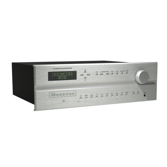
- Page 1 PREAMP / SURROUND PROCESSOR...
-
Page 2: Important Safety Instructions
(date code format is “yyww”, where “yy” is the two least significant digits of the year and “ww” is the week of the year) must be accompanied by a copy of the bill-of- sale from a Bryston authorized dealer to qualify for warranty service. The warranty is transferable from the original owner to a subsequent owner as long as a copy of the bill-of-sale from the original authorized Bryston dealer accompanies the re-sale. -
Page 3: Table Of Contents
SP3 PREAMP / PROCESSOR TABLE OF CONTENTS ■ Safety Instructions & Warranty . . . . . . . . . . . . . . . . . . .opposite page ■... - Page 4 12 have is rated for the electric power supply in your region. • Connect suitable inputs & outputs to the SP3. If you are connecting a DVD player to an SPDIF or TOSLINK in- put, connect it initially to SPDIF-1 or TOSLINK INPUT-1 (which are the default assignments;...
-
Page 5: Introduction, Safety, Accessories & Quick Start
HDMI inputs. The audio content will be processed screen. Use the up () and () down buttons to go through the SP3’s DSP but the video content will simply to these items. be passed through to the two (parallel) HDMI outputs. -
Page 6: Alpha-Numeric Display
If this button is selected and the supplied bitstream is channel signals. more than 2 channels, the decoder will automatically These will be detected by the SP3 and used to implement a stereo down-mix. Otherwise, analog or produce the down-mix if this mode is selected. -
Page 7: Stereo Down-Mix
Places the unit in standby mode. Status indicator LED is normally off when unit is operating. It turns red when unit The SP3 can send a different stereo audio source is placed in standby mode. When uploading new soft- signal to its ZONE outputs (Zone 2 Out) than to its main ware it may blink off and on in different colours. -
Page 8: Main / Zone Select
A conventional tape loop consisting of two pairs of RCA jacks; one stereo pair of inputs and one stereo pair of The SP3 offers both balanced (3 pin XLR male connec- outputs. A stereo down-mix for the selected source (or,... -
Page 9: Single Ended Analog Outputs
Risk of shock electric shock ~ do not open. Refer servic- 7: DIGITAL AUDIO COAXIAL INPUTS ing to qualified personel. Note, however, that the SP3 The TV/SAT, DVD, CD, and AUX front panel selectable does contain two 5x20mm glass fuses on the upper deck sources are also supplied with a standard SPDIF gold power supply board. -
Page 10: Single Ended Analog Inputs
A voltage of be- Right & Sub-woofer. tween 3 and 12V on the trigger input will turn the SP3 on. 19: BALANCED ANALOG INPUTS Removing the trigger voltage will cause the SP3 to turn off. -
Page 11: Fuses
MODEL PART NUMBERING SCHEME Model part numbers follow this scheme: The example at the left indicates an SP3 with a 17 inch wide silver (clear aluminum anodized) dress panel with a line voltage of 120VAC. -
Page 12: Infra-Red Remote Control & Codes
The SP3 Remote Control can operate all front panel operations in addition to having a MUTE button to for quickly silencing the output of the SP3. Certain features in the remote control itself... -
Page 13: Menu Tree
SP3 PREAMP / PROCESSOR MENU TREE SYSTEM SETUP SPEAKER DISTANCES (left) 09.0m, 0355 in., 030 ft., 026msec. (centre) 09.0m, 0355 in., 030 ft., 026msec. (right) 09.0m, 0355 in., 030 ft., 026msec. (right surround) 09.0m, 0355 in., 030 ft., 026msec. (right back) 09.0m, 0355 in., 030 ft., 026msec. -
Page 14: Menu Tree Notes
As a stereo pair, the signal is analog if the SP3 is in 2 The volume control can be used to adjust the output CHANNEL BYPASS mode or otherwise it is a digital levels during the test. -
Page 15: Specifications & Trademark Acknowledgements
SP3 PREAMP / PROCESSOR MENU TREE NOTES continued: or two back speakers. By turning the BACK speakers off, the surround sound speaker configuration becomes “5.1”. By choosing only 1 BACK speaker the configuration becomes “6.1”. SPECIFICATIONS PERFORMANCE SPECIFICATIONS A/D Conversion:... - Page 16 1x USB 2.0 type B OUTPUTS Analog Outputs: 10 balanced XLR male: Left, Centre, Right, Left Surround, Right Surround, Left Back, Right Back, Left Auxiliary, Right Auxil- iary and Subwoofer 16 sindle ended (unbalanced) RCA: Left, Centre, Right, Left Surround, Right Surround, Left Back, Right Back, Left Auxiliary, Right Auxil- iary &...
-
Page 17: Surround Speaker Placement Guide
SP3 PREAMP / PROCESSOR 5.1 SURROUND SPEAKER PLACEMENT GUIDE If the AUX output option is set as Center & Sub then a 2nd Center output is available allowing for two Center channel speakers to be used. Placement will be critical due to the largely voice band signals in this channel. -
Page 18: Surround Speaker Placement Guide
7.1 SURROUND SPEAKER PLACEMENT GUIDE... -
Page 19: Exterior Dimensions
SP3 PREAMP / PROCESSOR SP3 EXTERIOR DIMENSIONS... -
Page 21: Appendices
APPENDICES ■ Appendix A: SP3 Surround Sound Modes . . . . . . . . . . . . . 21 ■ Appendix B: RS232 Codes . . . . . . . . . . . . . . . . . . . 22-24 ■... -
Page 22: Appendix A: Sp3 Surround Sound Modes
2 is slightly delayed, so that any front channel sounds that leak channel music source signals. The custom SP3 Surround into the surround channel arrive at the listener after the front Modes use a set of DSP algorithms to create a set of simu- channels, providing an illusion of greater separation. -
Page 23: Appendix B: Rs232 Codes
04 DVR FOLLOWING SBVL Subwoofer Vol Trim SBVLxxxx 05 TAPE THE <CR> WILL BE IGNORED BY SP3. DO NOT 08 Digital Downmix UP Up 1 step (0.5dB) INSERT #, SPACES, <LF>, <TAB> OR OTHER DN Down 1 step (0.5dB) QS Query Status NON-PRINTABLE CHARACTERS INSIDE THE xxxx = 0880..1120... - Page 24 APPENDIX B: RS232 SERIAL CODES continued RBVL Right Back Vol Trim RBVLxxxx 00 not applicable or ignore 07 DRC MED1;DV OFF UP Up 1 step (0.5dB) AN Analog 08 DRC LOW2;DV OFF DN Down 1 step (0.5dB) DI Digital 09 DRC AUTO;DV OFF xxxx = 0880..1120 HD HDMI QS Query Status...
- Page 25 SP3 PREAMP / PROCESSOR APPENDIX B: RS232 SERIAL CODES continued 0c: AAC (MPEG4,MPEG2,iPhone, ff: unknown saved in EEPROM. iPod,iPad,NintendoDSi, (will require ASAVSV iTunes,DivX,PS3,PSP, VCPP Copy protection VCPPxx command to save!) SonyWalk,phones,Wii. status 01 ON Automatically saves all 0d: MPEG (MPEG1 Layer 1 and 2)
-
Page 26: Appendix C: Rs232 Port Hookup
RS232 commands sent will still be echoed back using standard reply format described in the helpcmd.txt Auto feedback is the response similar to an RS232 command response described in helpcmd.txt but issued by the SP3 to Host following a system status change, initiated by non-RS232 action. For example, when DVD front panel button is pressed SP3 would send #10MSRC00<CR>... -
Page 27: Appendix D: Hdmi Handshaking
Stan Bleszynski, Bryston Ltd . HDMI Handshaking When SP3 selects HDMI input port as its audio signal source, it acts as an HDMI repeater, placed in between HDMI signal source (DVD player, BD player etc) and HDMI signal “sink” (TV screen, TV projector etc). Every class of the devices on the HDMI chain has to respond to the HDMI handshake procedure, initiated by the signal source, that is by a player. - Page 28 The signal source determines the channel format. If the number of channels being played is not as expected, for example 2 instead of 5.1 or 7.1 then the SP3 and the player may have to re-handshake the communication protocol through HDMI in order to reset the proper status.
- Page 29 SP3 and a TV screen further down the HDMI device chain. This is determined by the maximum capability of the SP3 (Video up to 1080p, 3D, color depth 36, audio 7.1 channels up to 192kHz sample rate).
- Page 30 APPENDIX D: HDMI NOTES continued Note: some Blue-Ray players tend to block Bitstream selection, performing automatic conversion to PCM, when Secondary Audio Output option is enabled! References: http://en.wikipedia.org/wiki/HDMI http://www.hdmi.org/learningcenter/kb.aspx HDMI Notes, Part 1 Page 4 of 4...
-
Page 31: Appendix E: Usb Guide
Make sure SP3 is connected to a power source but in Standby. When the USB cable connecting SP3 is plugged to a USB port in a PC and SP3 is taken out of Standby, a message Driver Software Installation is produced in the system tray area. Clicking on it opens up the following message window: Message screen on USB connection event. - Page 32 APPENDIX E: USB GUIDE continued Selecting “BRYSTON SP3” as the default Audio Device. Sound Manager window (from the System Tray) Click on the “Speakers/BRYSTON SP3” line to make this the default. SP3 USB User Guide Page 2 of 3...
- Page 33 Player, then select and click one of the sample music files. Configuring MAC OS for USB streaming to SP3. The idea is the same as in Windows, that is Bryston SP3 has to be selected as the output audio device. The following screenshots illustrate the necessary steps: Step 1 - In Utilities select Applications, then Audio MIDI Setup Step 2 - Select BRYSTON SP3 and "Use this device..."...
-
Page 34: Appendix F: Web Interface Guide
2012-08-02, Stan Bleszynski, Bryston Ltd. 1. General guidelines (introduction). SP3 can be connected to a PC (Windows, MacOS, Linux etc) using Ethernet cable through a local area network hub or through a direct peer-to-peer (SP3-to-PC) using a cross-over network cable. Connection between SP3 and a PC can be established using either one of the 3 basic configuration schemes differing in the way the IP addresses are leased out or assigned by an external or internal DHCP server. - Page 35 SP3 PREAMP / PROCESSOR APPENDIX F: WEB INTERFACE GUIDE continued Bios Name” of the SP3, or its IP address in the browser URL window and pressing enter, should bring on the following screen: 2. File upload screen. Click on the top “File” menu link on the main SP3 web interface screen brings the “Firmware Upload” screen.
- Page 36 Note: selecting of “Restricted Default Flash Partition” allows overwriting of backup files in the SP3 flash. This option is normally not enabled and a special password would be required. SP3 Web Interface Guide...
- Page 37 SP3 PREAMP / PROCESSOR APPENDIX F: WEB INTERFACE GUIDE continued 3. Setup screen Setup screen This screen displays network-connectivity settings and also allows modification of: DHCP mode selection, IP address, Gateway IP address, Subnet Mask, Primary DNS and Secondary DNS.
- Page 38 To replace the fuse, locate it in the far left corner inside the unit, after opening up the top cover. This screen will be modified in the future to display information available currently on the SP3 Vacuum Fluorescent display in menus SYSTEM SETUPTESTSYSTEM STATUS and HDMI STATUS.
- Page 39 SP3 PREAMP / PROCESSOR APPENDIX F: WEB INTERFACE GUIDE continued 5. Help screen. Help screen as of release 2012.04 (top part) The top part of the Help screen contains 3 important links to documents: User Manual – an on-line version of the user manual (this link requires an active Internet connection to work)
- Page 40 LED is lit. Note: some of the help hyperlinks point to embedded files in the SP3, while some other, such as the user manual, point on-line thus require active internet connection.
-
Page 41: Appendix G: Subwoofer Setup
(if there are any), otherwise it will be cut- off. SP3 provides a single subwoofer channel through back panel RCA socket paralleled with an XLR socket. Optionally, it can also output the subwoofer channel through the Aux R socket. - Page 42 APPENDIX G: SUB-WOOFER SETUP continued Source Setup Screen Volume level corrections (from -12 to +12dB) can be entered for each speaker individually in the SPEAKR LEVEL screen. Cross-over frequencies can be modified in CROSSOVER and subwoofer configuration is in SUBWOOFER submenu. Subwoofer setup screen (Small speakers) Subwoofer setup screen differs between the situation when the Front speakers were declared as “Small”...
- Page 43 Subwoofer in Xtra Bass (on top of the normal Subwoofer Level correction from SOURCE SETUPSPEAKR LEVEL). It is disabled and not applied if Extra Bass is not 5. Interpretation of the x.1 and x.0 symbols on the SP3 idle screen “IN:…” line: Symbol ".1"...
- Page 44 APPENDIX G: SUB-WOOFER SETUP continued Symbol ".1" or ".0" (as in the “OUT: PL2xMovie7 EX 7.1” above) indicates a usage or a lack of usage of the Subwoofer speaker and is a function of the output configuration and the presence of the input LFE channel. There are two cases: a) Front speakers are Small: If you select Subwoofer ON, then you will always see OUT:…...
-
Page 45: Appendix H: Local Area Newtork (Lan) Setup
This method is described in more details below in section 2. In most configuration where the LAN card of the host PC is set up for static IP address, SP3 would connect regardless of the DHCP selection, though “STATIC IPadr” is recommended. “NetBios Name” addressing cannot be used in this scheme (for... - Page 46 This setup uses peer-to-peer physical connection using a cross-over Ethernet cable, connecting the Ethernet port on the back of SP3 unit, directly to the second LAN2 card in the host PC. To set up the SP3, press right arrow key to enter the menu system, then: SYSTEM SETUPMISCELLANEOUS...
- Page 47 In order to ensure that the main LAN connection is not disrupted by the presence of a local side subnet, the main LAN card may require specifying a proxy server, and at the same time the static SP3 address must be excluded from the proxy, as showed in the following screen dump: Configuration example of the main network card (LAN) for normal LAN connectivity, allowing for the SP3 static IP scheme.
- Page 48 APPENDIX G: SETUP USING LAN continued Running ipconfig/all from the Windows (7 or XP) command line allows us to verify the connections. A typical display should look as below: ipconfig/all screen dump SP3 to LAN Setup Guide Pg. 4 of 4...
-
Page 49: Appendix I: Dolby Volume/Drc Setup
SP3 PREAMP / PROCESSOR APPENDIX I DOLBY VOLUME/DRC SETUP DOLBY VOLUME/DRC Screen 2012-08-02 Stan Bleszynski, Bryston Ltd. 1. Bringing up the Dolby Volume/DRC screen. Pressing a down arrow key while the default (idle) screen is being displayed brings up the Dolby Volume screen for a about 10 seconds. - Page 50 –20.0..+20.0dB. This parameter defines the maximum sound level for the This is equivalent to DYNAMIC RANGE MEDIUM selection in SP1.7, SP2 This is equivalent to DYNAMIC RANGE LOW selection in SP1.7, SP2 SP3 Dolby Volume/DRC Screen Page 2 of 3...
- Page 51 <=48kHz. It is automatically disabled above 48kHz but this is not indicated on screen! No configuration settings are available for DRC selections. +6dB is often sufficient to adjust the loudest movie scenes down to a comfortable level. SP3 Dolby Volume/DRC Screen Page 3 of 3...
-
Page 52: Appendix J: Firmware Update/Upload Instructions
PC with a network cable. Make sure that a green light at the SP3 network socket (back panel) is lit. If not then use a cross-over cable or verify that the network interface to which SP3 is connected, is enabled. - Page 53 APPENDIX J: FIRMWARE UPLOAD INSTRUCTIONS continued 5. Click on the “Upload Image File (.bin)” button to open the next screen: “File Package Upload” page of the SP3. 6. Click on “Browse” button to select the file, and type the path and name of the firmware file (case-sensitive).
- Page 54 Uploading is marked by a live time count on the SP3 front panel screen but during the last self programming stage the screen goes blank while the Standby LED will be flashing some red, yellow and green patterns (or red, violet and blue).
- Page 55 Do not unplug or power off the unit and wait ten more seconds for the Standby LED to go dark after the main screen shows up, before using the SP3. Press the left arrow on the front panel to display the serial number and firmware revision, verifying that the revision number has been updated to a new value.
- Page 56 LED is still lit, or accidental power down. SP3 Software Upload Instructions Page 5 of 6...
- Page 57 SP3 PREAMP / PROCESSOR APPENDIX J: FIRMWARE UPLOAD INSTRUCTIONS continued It is recommended to follow it, that is go to Miscellaneous menu, and scroll down to DEFAULT EEPROM option , press Surround arrow key to select "DO IT" and execute the action by exiting the screen, pressing left arrow.
-
Page 58: Appendix K: Sp3 Control Via Rs232 & Tcpip
To unlock the hidden screens got to the last miscellaneous screen and then press ZONE,DVD and TAPE buttons, in this order SP3 may have additional unsupported commands that are exceptions to Bryston Serial Protocol, for example a common help displaying command is a single question mark character or some test and diagnostic commands that are implemented for the purpose of trouble-shooting. - Page 59 , by issuing a single-character special question mark command ? : If you use a network connection ithout a server or router, type in the actual IP address instead of the “sp3- <ser.num>” Default baud rate is 9600bps, 1 start bit, 8 bits, no parity, 1 stop bit. A baud rate and a feedback selection can be set by MISCELLANEOUSRS232 BAUD and RS232 MODE parameters.
- Page 60 The same question mark command (or any other SP3 command ) can also be issued by typing the ? character in the command window on the main SP3 web page and pressing Enter (or clicking the Cmd button) to execute. This will make a scrollable text window expand displaying the embedded help page.
- Page 61 APPENDIX K: SP3 CONTROL VIA RS232 & TCPIP continued SP3 virtual front panel main web page (http://sp3-<ser.num.>) Ending of a command by a dot character is not necessary when typing it in the SP3 web interface window, but mandatory when issuing the GET command programmatically or from a browser’s URL window.
- Page 62 SP3 to host, type the following text into the URL window and press Enter http://169.254.1.1/status.xml This will cause the SP3 system status data to be read from the SP3, including a response from the previously sent control command (in this case MSRCQS), to appear in the main browser window, for example: The actual IP address can be viewed on the serial number screen displayed by pressing the left arrow navigation key on the front panel or IR remote.
- Page 63 SP3 PREAMP / PROCESSOR APPENDIX K: SP3 CONTROL VIA RS232 & TCPIP continued SP3 system status and command (MSRCQS) response polled and passed through status.xml data block. Note: SP3 response to a Bryston serial Protocol command is contained within the tags: <tw0>..<tw0> <tw7>..<tw7>...
- Page 64 Above sequence passes a command (in this case selection of input source “MSRC”) from a host to SP3. In order to pass data (i.e. command response) in the reverse direction, from the SP3 to the host, type the following into the Telnet terminal window and press enter: GET /status.xml HTTP/1.0...
-
Page 65: Appendix L: Pink Noise Test
(see http://en.wikipedia.org/Pink_noise ). Sound pressure meter is an external accessory not included with the SP3. If all speakers are enabled then it will go through L,C,R,Rs,Rb,Lb,Ls and Subwoofer (subscript s means “side surround”, b –... - Page 66 3. Starting by TEST button on the infrared remote controller. SP3 goes to the "Pink Noise" screen and starts playing the noise in the AUTOCYCLE mode, the same as when selecting it by the front panel through TEST submenu, except that it will exit automatically after the last speaker channel in the sequence (typically subwoofer) finished playing.
- Page 67 SP3 PREAMP / PROCESSOR APPENDIX L: SP3 PINK NOISE TEST continued 4. Pink Noise spectrum Fig. 4.1 Pink Noise spectrum 5. Band-limited noise spectrum. Pink Noise Test 2012-03-05 Page 3 of 4...
- Page 68 APPENDIX L: SP3 PINK NOISE TEST continued Pink Noise Test 2012-03-05 Page 4 of 4...
-
Page 69: Appendix M: Idle Screen Explanations
SP3 PREAMP / PROCESSOR APPENDIX M IDLE SCREEN EXPLANATIONS SP3 IDLE SCREEN EXPLANATIONS 2011-11-24 SP3 DEFAULT SCREEN 1. Default screen, playing SPDIF input, PCM-encoded 2 channel stream, example Source Input type (digital, analog, hdmi, bypass) Line1: SRC: AES1 DIG Program encoding: linear PCM 2ch Sample rate (kHz) Program format (front/surr/back.lfe) - Page 70 APPENDIX M: SP3 IDLE SCREEN EXPLANATIONS continued 2. Default screen, playing HDMI input, Dolby Digital encoded multi-channel stream, example 2 Source Input type (HDMI input socket #1) Line1: SRC: DVD HDMI1 Program encoding Dolby Digital Sample rate (kHz) Program format (numspeakers.lfe) Line2: IN: Dd Digital 48k 5.1...
- Page 71 SP3 PREAMP / PROCESSOR SP3 PREAMP / PROCESSOR APPENDIX M: SP3 IDLE SCREEN EXPLANATIONS continued 3. Default screen, playing HDMI input, DTS-encoded multi-channel stream, example 3 Source Input type: Optical (Toslink), socket #2 Line1: SRC: DVD OPT2 Program encoding: Digital Theatre System Sample rate (kHz) Line2: IN: DTS 48k 5.1...
- Page 72 300024-12-20140410 SP3 Owner’s Manual, Revision 12...
Need help?
Do you have a question about the SP3 and is the answer not in the manual?
Questions and answers