
Related Manuals for Bryston SP1.7PRECISION


Summary of Contents for Bryston SP1.7PRECISION
- Page 1 SP1.7 S E R I E S I N S T R U C T I O N S F O R B R Y S T O N S P 1 . 7 P R E C I S I O N P R E A M P L I F I E R / P R O C E S S O R...
- Page 2 The warranty is fully transferable to the original owner and all subsequent owners during the warranty period. Warranty coverage is automatic and commences with the original date of manufacture which is kept on file at Bryston. In the event of a defect or malfunction, contact Bryston’s repair centers for return authorization.
-
Page 3: Table Of Contents
Congratulations on your purchase of the Bryston SP1.7 pre-amplifier/processor. This product will provide you with the finest available signal control and DSP audio processing available. Like all Bryston products the SP1.7 has been carefully designed and engineered to deliver a lifetime of enjoyment. - Page 4 1 IEC standard power cord 1 SP1.7 Infrared Remote Control unit with backlight and battery installed It is VERY IMPORTANT that you read and completely understand the Bryston Safety Manual before installing or connecting the SP1.7 to any electrical power source.
- Page 5 POWER The SP1.7 uses a dual mode electrical power system. In the electrical power input module located on the right hand side of the rear panel, adjacent to the IEC power cord socket is a large computer-style switch that controls the main electrical power to the unit.
-
Page 6: Dynamic Range Control
FRONT PANEL CONTROLS AND INDICATORS When looking at the front panel of the SP1.7 you will see the following controls and displays from left to right: Power [Momentary Switch] Toggling this switch up or down takes the unit in and out of its’ Standby power mode. -
Page 7: Using The Dynamic Range Control
SP1.7. This screen is also used during the menu-setup function for calibration of the SP1 to your system. If connected to the Bryston SPV-1 Video Switcher, the menu-setup and status display will also be available on your video monitor with On-Screen Display (OSD). -
Page 8: Menu Control Buttons
6. Menu Control Buttons These three buttons labeled “<”, “>”, and “SEL” (SELECT) are used to control the menu/setup functions displayed on the LCD. To enter a menu mode, you can press any one of these buttons. This will bring up the main menu. Navigating any menu or sub-menu is done using the two arrow (<... -
Page 9: Mode Selection Buttons
MODE SELECTION BUTTONS: 8. Digital Mode and Indicator This button operates as a three-way toggle function. The LED immediately above the button has two colors - RED and GREEN, and an OFF mode where it is not illuminated. When Digital Mode is selected, the decoder will automatically default to a digital signal for the selected input if one is present. - Page 10 10. Stereo and Stereo Downmix Mode If this button is selected and the supplied bitstream is more than 2 channels, the decoder will automatically implement a stereo downmix. Otherwise, analog or digital two channel signals are passed as conventional stereo. STEREO 11.
- Page 11 12. THX Button Pressing this button will engage the SP1.7’s default THX listening mode. The default mode is selected using the “EX Control” menu (see page 26). NOTE: THX Surround EX™ decoding is only available in the THX listening mode. If the “EX Control”...
-
Page 12: Mode Button
Mode Button This button is used to select one of 13 effects for synthesizing surround sound with 2-channel source material. Pressing the button repeatedly will scroll through the modes: MODE You can select a Surround Mode for the Surround or THX listening modes at any time, even if the effect is not immediately active (such as the case when a 5.1 channel bitstream is present). -
Page 13: Master Volume
LED will be GREEN. In Bypass 2ch mode all of the DSP circuitry, DA and AD converters are bypassed, allowing a completely analog circuit path, identical to the reference standard Bryston BP-25 pre-amplifier. Only standard format Stereo operation is permitted in this mode - all other BYPASS functions are disabled. -
Page 14: Analog Inputs
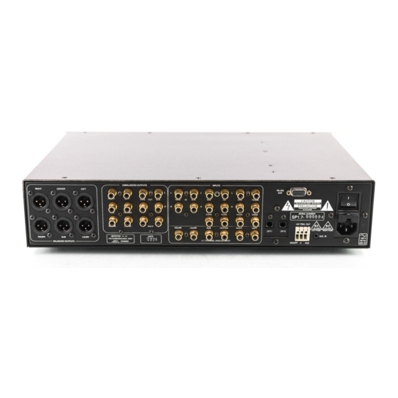
REAR PANEL INPUT AND OUTPUT CONNECTIONS RIGHT CENTER LEFT RIGHT RSURR BRYSTON RSURR LSURR PETERBOROUGH, ONT. MADE IN BALANCED OUTPUTS FABRIQUE AU 1. Balanced and 2. Unbalanced Outputs The SP1.7 offers both balanced (5.1) and unbalanced (7.1) outputs for power amplifiers or powered loudspeaker systems. -
Page 15: Setting The Optical Input Assign
5. TOSLINK Digital Audio Optical Inputs The SP1.7 offers two assignable TOSLINK optical inputs. These can be designated to any input using the OS menu (“Other Settings”)on the LCD screen. Please note that if you choose to assign an optical input to an input with a coaxial input, the coaxial will be over-ridden and the optical input signal will be used by the SP1.7. -
Page 16: Programming The Aux Trigger Output
IR receiver. 9. RS-232 connector This connection provides for control of a Bryston SPV-1 video switcher, or remote control of the SP1.7 functions via a computer interface or AMX/Crestron type controller. Please contact your dealer or Bryston to make use of this optional feature and determine which devices are compatible. -
Page 17: Master Power Switch
10. IEC Power Connector 11. Fuses Please note that the Analog and Digital power supplies are fused separately. Replace fuses ONLY with an exact equivalent to avoid damage to the SP1.7. 12. Master Power Switch THE SP1.7 REMOTE CONTROL CODE CODE POWER POWER... -
Page 18: Power Button
7. Power Button Pressing this button will toggle the SP1.7 in and out of the Standby power mode. {Installers: please contact Bryston technical support for information about Discrete On/Off control} 8. Save Button Pressing this button will memorize settings for the current input, as described in “Saved Settings per Source”... -
Page 19: Status Led
Press CODE button and release ii. LED will illuminate (Red) iii. Type in 3 digit code (a combination of mode buttons) iv. LED will flash again to confirm and go out. For a list of hidden codes, visit the Bryston Website at www.bryston.ca... -
Page 20: Setup And Calibration Of The Sp1.7
Record the dB level from this speaker (with the level trim value at 0 dB on the LCD Display or on the Video Monitor when using the Bryston SPV-1), and adjust all the others to match it. It is not critical to reach some specific dB level (ex. -
Page 21: Explanation Of 'Saved Settings Per Source
Explanation of ‘Saved Settings per Source’ Feature The SP1.7 will remember different mode settings for each source. Every time a source is engaged it will recall the following settings: Digital Status Listening Mode (Surround, THX, Stereo, Mono) Surround Mode Bypass Status Subwoofer Level Rear Channel Levels Back Channel Levels... -
Page 22: Explanation Of 'Xtra Bass' Mode
The options available in this menu are: For LEFT/RIGHT (LR) you can select SMALL OR LARGE For CENTRE (C) you can select SMALL, LARGE or NONE FOR SURROUNDS (SUR) you can select SMALL, LARGE or NONE FOR BACK (BK) you can select NONE, ONE or TWO FOR SUBWOOFER (SUB) you can select YES or NO The SP1’s default factory settings as shipped are: Left/Right = LARGE... -
Page 23: Enabling The Subwoofer Output In The Bypass Mode
1. None: no subwoofer attached to the system. 2. Yes - Xbass Off: subwoofer is active, but only active with LFE tracks if the front speakers are full-range 3. Yes - Xbass On: subwoofer is active in system, in addition to full-range speakers. NOTE 1: the Xbass settings only show up in the menu if the front speakers are defined as ‘Large’. -
Page 24: Setting The Channel Delays
3. Next move the cursor to ‘XO’. Hit ‘SELECT’ - You are now in the Crossover Menu. The options available in this menu are either NONE or 60 Hz to 220 Hz in 10 Hz increments. The SP1.7’s default factory setting as shipped is the THX standard 80 Hz crossover frequency. - Page 25 3. Move the cursor to the speaker you want to set the distance/delay for (L C R RS LS RB LB SB). Hit Select. Now you can adjust the Delay value which is equivalent to the distance you measured for the selected speaker using the arrow buttons.
-
Page 26: Setting The Thx Subwoofer Limiter Or Bass Peak
1.`First enter the main menu by pressing on any one of the menu buttons on the SP1.7 front panel (< - > or SELECT). 2. Next move the cursor to “LVL”. Hit ‘SELECT’ - You are now in the Level Trim Menu. 3. -
Page 27: Enabling Dts-Es 6.1 Decoding
3. Hit ‘SELECT’ and you will see the adjustment screen picture below appear, and you will hear a low level Pink Noise signal coming from your subwoofer and/or large speakers. Figure 21: BPLM Routine for level setting Now you can adjust the value of the subwoofer limiter (-24 to 0 dB). Slowly increase the level by pressing the “>”... -
Page 28: Enabling Thx Surround Ex™ Decoding
2. Next move the cursor to “OS”. Hit ‘SELECT’ – you are now in the ‘Other Settings’ menu. 3. Move the cursor to “ES”. Hit ‘SELECT’ – you can now change the ES Control setting. The options available in this menu are: DISABLE –... -
Page 29: Changing Dolby Plii Music Settings
3. Move the cursor to “EX”. Hit ‘SELECT’ – you can now change the EX Control setting. Figure 27: Change “EX” Control Setting The options available in this menu are: DISABLE – THX Surround EX™ will not be decoded ON – THX Surround EX™ will be forced on for all Dolby Digital 5.1 channel input bitstreams, if the back channels are enabled. - Page 30 PLII Film This is the preferred decoding method for watching movies with matrix surround encoding. The centre width and dimension variables are set and optimized for this application, and cannot be adjusted. No filters are present on the surround channels, and autobalance is operational. PLII Music This mode can enhance normal stereo music recordings, offering a wider soundstage and enhanced spatial effects.
-
Page 31: Changing Dts Neo:6 Settings
3. Move the cursor to the setting you want to change. The options are: CEN – center width (0 to 7; default 3) DIM – dimension (-3 to +3; default 0) PAN – panorama (YES or NO; default NO) Hit ‘SELECT’ – you can now change the chosen PLII setting. Figure 30: Change the PLII Centre Width Setting Changing DTS NEO:6 Settings Neo 6 provides up to six full-band channels of matrix decoding from stereo matrix material. - Page 32 To change the Center Image: 1. First enter the main menu by pressing on any one of the menu buttons (< - > or SELECT) 2. Next move the cursor to “DTS”. Hit ‘SELECT’ – you are now in the ‘DTS Settings’ menu. 3.
-
Page 33: Appendix A - Sp1.7 Surround Modes
APPENDIX A - SP1.7 Surround MODES Pressing the MODE button will illuminate the LED and let you sequentially select one of the many available decoding modes for 2 channel signals. These special modes are designed to expand your enjoyment of almost any 2 channel music source and many other 2 channel signals. - Page 34 Party. The Party (Five-Channel Mono) Mode converts stereo input to a mono signal which is then distributed to the five satellite channels. Stereo5. The Stereo5 (Five-Channel Stereo) Mode converts stereo input to surround sound. The stereo signal is distributed to the five satellite channels, creating a giant stereo image in your listening space. (Please note that the apparent effect of the Surround Mode can be adjusted by altering the delay parameters and channel volume of the centre, surrounds and back channel(s), using the appropriate menus).
- Page 35 Table of all available surround modes. Signal Listening Surround Mode Effect DD 5.1 Surround DD 5.1 DD 5.1 DD 5.1 Stereo DD 5.1 Mono DTS 5.1 Surround DTS 5.1 DTS 5.1 Surround DTS 5.1 DTS 5.1 Stereo DTS 5.1 Mono DTS-ES Discrete Surround DTS-ES Discrete...
-
Page 36: Appendix B - Thx Information
APPENDIX B - THX INFORMATION Below is a summary of issues and information related to the proprietary and patented THX processing incorpo- rated used in the SP1. The available space cannot include all the available information on this topic. Therefore, if you want more information or wish to research the topic in more detail please use the THX website at WWW.THX.COM. -
Page 37: Example Hook-Up Diagram
P1/SLEEVE=GND P1/SLEEVE=GND trademark of trademark of trademark of trademark of LUCASFILM. LUCASFILM. LUCASFILM. LUCASFILM. BRYSTON For HOME THEATRE: For HOME THEATRE: BALANCED: 2V BALANCED: 2V SINGLE ENDED: 1V SINGLE ENDED: 1V 9B-SST POWER (See manual) (See manual) (See manual) -
Page 38: Sp1.7 Specifications
SP1.7 SPECIFICATIONS Inputs Analog Audio: Six stereo (RCA) pairs, One 5.1 channel (RCA) input Digital: 4 coaxial (RCA) 75 Ohms, 2 Optical (TOSLINK?), conforms to S/PDIF standard. Pro version 1 AES/EBU input (XLR) 110 Ohms Infrared: 1 mini phone jack RS-232: D9 connector (bidirectional) Outputs... -
Page 39: Suggested Surround Sound Placement
SUGGESTED SURROUND SPEAKER PLACEMENT Figure 35 – Suggested Surround Speaker Placement... - Page 40 SP1pt7_MANUAL_20060112...
Need help?
Do you have a question about the SP1.7PRECISION and is the answer not in the manual?
Questions and answers