Table of Contents
Advertisement
Quick Links
Download this manual
See also:
User Manual
Advertisement
Table of Contents

Related Manuals for Moxa Technologies V481


Summary of Contents for Moxa Technologies V481
- Page 1 V481 Hardware User’s Manual Fourth Edition, June 2009 www.moxa.com/product © 2009 Moxa Inc. All rights reserved. Reproduction without permission is prohibited.
-
Page 2: Copyright Notice
V481 Hardware User’s Manual The software described in this manual is furnished under a license agreement and may be used only in accordance with the terms of that agreement. Copyright Notice Copyright © 2009 Moxa Inc. All rights reserved. Reproduction without permission is prohibited. -
Page 3: Table Of Contents
Table of Contents Chapter 1 Introduction ....................1-1 Overview ..........................1-2 Package Checklist......................... 1-2 Product Features ........................1-3 Product Hardware Specifications ..................1-4 Hardware Block Diagram..................... 1-6 Chapter 2 Hardware Introduction ................2-1 Appearance........................... 2-2 Dimensions (unit = mm)....................... 2-3 LED Indicators ........................2-3 Power On/Off Button ...................... - Page 4 Resume by Alarm....................4-13 HW Monitor ........................4-14 CPU Warning Temperature ................... 4-14 Load Defaults ........................4-15 Load System Default Settings................4-15 Load CMOS From BIOS ..................4-15 Save CMOS To BIOS ................... 4-15 Exiting the BIOS Setup ...................... 4-15 Chapter 5 Upgrading the BIOS ..................5-1...
-
Page 5: Chapter 1 Introduction
LAN ports, 8 serial ports, 2 CompactFlash slots, and 2 USB ports, and is based on the Intel x86 processor. With its VGA interface, the V481 is especially well suited for industrial applications, such as SCADA, factory automation, and other applications that require an onsite HMI or visual monitoring capability. -
Page 6: Overview
1 GHz processor. In addition to the usual computer peripherals, the V481 integrates one 10/100 LAN port, one Gigabit LAN port and 8 RS-232/422/485 serial ports, making the V481 into an ideal industrial embedded computer for handling industrial communication applications that need to connect to a monitor or HMI onsite. -
Page 7: Product Features
NOTE: Please notify your sales representative if any of the above items are missing or damaged. Product Features The V481 embedded computers have the following features: Intel Celeron M 1GHz CPU, 400 MHz FSB IDE hard disk support (for product produced after 1st June) -
Page 8: Product Hardware Specifications
V481 Hardware User’s Manual Introduction Product Hardware Specifications System CPU: Intel ULV Celeron 1GHz processor without L2 Cache System Chipset: Intel 852GM GMCH + ICH4 chipset FSB: 400 MHz BIOS: 4 Mbit Flash BIOS; supports Plug & Play System Memory: 200-pin SO-DIMM socket x 1 with built-in 256 MB DDR for WinCE 5.0 model;... - Page 9 V481 Hardware User’s Manual Introduction Buttons Power Button: Power on/off x 1 Resent Button: Reset button for system warm reboot x 1 Power Requirements Power Input: 9 to 36 VDC Power Consumption: 25W, 650 mA @ 36 VDC, 2750 mA @ 9 VDC...
-
Page 10: Hardware Block Diagram
V481 Hardware User’s Manual Introduction Hardware Block Diagram RS-232/422/485 Intel Celeron M 1 GHz Compact- MOXA ART PCI 104 BIOS Flash MU860 Slot Intel GMCH Intel SDRAM 86852GM ICH4 Super I/O Keyboard/ Audio LAN1 LAN2 Mouse Host... -
Page 11: Chapter 2 Hardware Introduction
The LED indicators allow users to monitor performance and identify trouble spots quickly, and the multiple ports can be used to connect a variety of devices. The V481 comes with a reliable and stable hardware platform that lets you devote the bulk of your time to application development. -
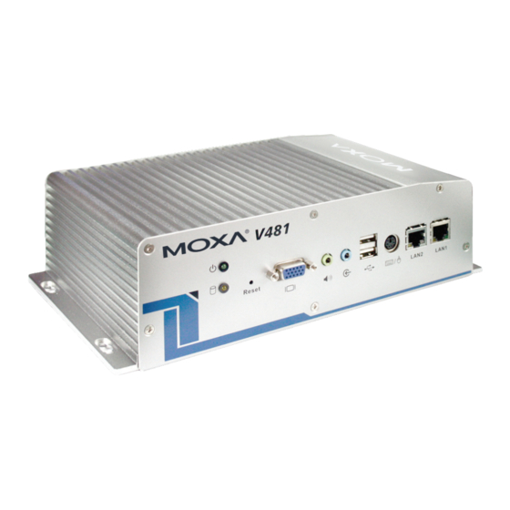
Page 12: Appearance
V481 Hardware User’s Manual Hardware Introduction Appearance Rear View Power But t on Power Input Serial Ports x 8 9-36 VDC RS-232/422/485 Top View Front View... -
Page 13: Dimensions (Unit = Mm)
V481 Hardware User’s Manual Hardware Introduction Dimensions (unit = mm) LED Indicators There are 6 LED indicators located on the front panel of the V481. LED Name LED Color LED Function Green Power is on Power No power is being received, or power error exists Yellow Data is being written to or read from the storage unit. -
Page 14: Power On/Off Button
Placement Options Wall or Cabinet The V481 has wall-mount ears for attaching the V481 to a wall or the inside of a cabinet. Use screws to attach the V481 to a wall or cabinet, as illustrated in the following figure. -
Page 15: Din-Rail Mounting
DIN-Rail Mounting An aluminum DIN-Rail Mounting Kit is included with the V481. If you need to reattach the DIN-Rail kit to the V481, make sure the stiff metal spring is situated towards the top, as shown in the following figures. -
Page 16: Hardware Connection Description
The V481 embedded computers are equipped with multiple connection types: VGA, Ethernet, multiple serial interfaces, and PS2 connectors are built into the V481. The V481 also has a CompactFlash socket for storage expansion, USB ports for additional device and storage options, and an audio interface. -
Page 17: Wiring Requirements
V481 Hardware User’s Manual Hardware Connection Description Wiring Requirements In this section, we describe how to connect serial devices to the embedded computer. You should heed the following common safety precautions before proceeding with the installation of any electronic device: Use separate paths to route wiring for power and devices. -
Page 18: Grounding The Unit
DC 9-36V Connecting to a Display The V481 comes with a D-Sub 15-pin female connector to connect a VGA CRT monitor. To ensure that the monitor image remains clear, be sure to tighten the monitor cable after connecting it to the V481. The pin assignments of the VGA connector are shown below. -
Page 19: Connecting To A Keyboard And Mouse
Hardware Connection Description Connecting to a Keyboard and Mouse The V481 has a PS/2 connector for connecting a PS/2 keyboard or PS/2 mouse by using a Y-type cable. This 6-pin mini-DIN connector has the following pin assignments, which depend on the version of the product. -
Page 20: Connecting Data Transmission Cables
V481 Hardware User’s Manual Hardware Connection Description Connecting Data Transmission Cables In this section, we describe how to connect to the network and to serial devices. Connecting to the Network Plug your network cable into the embedded computer’s Ethernet port, and plug the other end of the network cable into your Ethernet network port. -
Page 21: Installing A Memory Module
1. Disconnect the V481 from the power source. 2. Unscrew the V481’s bottom cover. 3. Grab hold of the main screw and lift to remove the V481’s bottom cover. 4. Plug a DDR SDRAM module into the 200-pin SO-DIMM socket; be sure to situate the module correctly. -
Page 22: Inserting A Compactflash Card
1. Disconnect the V481 from the power source. 2. Unscrew the V481’s bottom cover. 3. Grab hold of the main screw and lift to remove the V481’s bottom cover. You will see that the socket is attached to the bottom cover. -
Page 23: Inserting A Hard Drive Disk
Hardware Connection Description Inserting a Hard Drive Disk The V481 offers an IDE-based connector, allowing users to connect a 2.5” hard drive disk with IDE interface so that the additional storage expansion can be made. To insert a CompactFlash card, please follow these instructions. -
Page 24: Usb Hosts
5. When finished, attach four screws to fasten the disk. USB Hosts The V481 has two USB 2.0 ports. Both ports are UHCI, Rev. 2.0 compliant and support Plug & Play and hot swapping. The ports can be used to connect USB devices, such as a keyboard, mouse, USB flash disk, and USB CD-ROM. -
Page 25: Chapter 4 Bios Setup
BIOS Setup Chapter 4 In this chapter, we explain how to configure the V481’s BIOS settings. The built-in BIOS setup program allows users to configure basic settings for the entire computer system. All of the configurations are stored in the CMOS RAM, which is connected a battery back-up. This means that the configuration settings will be stored in the CMOS RAM even if the computer is powered down. -
Page 26: Entering The Bios Setup Utility
V481 Hardware User’s Manual BIOS Setup Entering the BIOS Setup Utility To enter the BIOS setup utility, please press the Del key after booting up the system. The main BIOS Setup Utility screen will appear, as shown below. A basic description of each function key is listed at the bottom of the screen. Refer to these descriptions to learn how to scroll about the screen, how to select by pressing “Enter”... -
Page 27: Modifying The Bios Main Settings
V481 Hardware User’s Manual BIOS Setup Modifying the BIOS Main Settings Basic Configuration After entering the BIOS Setup Utility, or after choosing the “Main” option, the BIOS main menu will be displayed. Use this menu to check the basic system information, such as the memory and IDE hard drive. -
Page 28: Modifying The Bios Advanced Settings
V481 Hardware User’s Manual BIOS Setup Once a password has been set, you will be prompted to enter the password each time you enter Setup. This prevents unauthorized persons from changing any part of your system configuration. In addition, when a password setting is enabled, you can set up the BIOS to request a password each time the system is booted up. -
Page 29: Advanced Bios Settings
V481 Hardware User’s Manual BIOS Setup Advanced BIOS Settings When you select the “Advanced BIOS Features” option under the “Advanced” menu, the “Advanced” configuration menu will appear. CPU Feature “Press Enter” to configure “CPU Feature” settings. Virus Warning The “Virus Warning” setting will protect the IDE Hard Disk boot sector. If an attempt is made to write data into the boot sector, the BIOS will display a warning message on the screen, and the BEEP warning function will be enabled. -
Page 30: Advanced Chipset Settings
V481 Hardware User’s Manual BIOS Setup Typematic Rate Setting Enable the “Typematic Rate Setting” to adjust “Typematic Rate” and “Typematic Delay.” These settings determine the repeat rate when depressing any key. Disable this feature to keep the factory default values of 6 for “Typematic Rate” and 250 for “Typematic Delay.”... -
Page 31: Dram Timing Selectable
V481 Hardware User’s Manual BIOS Setup DRAM Timing Selectable It allows user to configure the DRAM clock / timing. To choose “By SPD” if the memory module support “SPD” (Serial Presence Data), or choose “Manual” to do the advanced configuration described below. -
Page 32: Pnp/Pci Configurations
V481 Hardware User’s Manual BIOS Setup Delay Prior to Thermal Select the delay time before thermal activation due to high temperatures. Users may select “4 Min,” “8 Min,” “16 Min,” or “32 Min.” The default value is “16 Min.” AGP Aperture Size (MB) “AGP”... -
Page 33: Frequency/Voltage Control
V481 Hardware User’s Manual BIOS Setup Resources Controlled By When the default setting of “Auto (ESCD)” is selected, the system BIOS will automatically assign the IRQ, DMA, and base address resources for all compatible PnP / PCI devices when the system boots up. -
Page 34: Configuring Peripherals
V481 Hardware User’s Manual BIOS Setup Configuring Peripherals You may adjust the relevant settings of integrated peripherals after selecting the “Peripherals” option from the BIOS main menu. Select from the following options: “OnChip IDE Device,” “Onboard Device,” and “Onboard I/O Chip Setup.”... -
Page 35: Onboard Device
V481 Hardware User’s Manual BIOS Setup IDE HDD Block Mode IDE HDD Block mode is used for block transferring, multiple commands, and multiple sector read/write. When this option is enabled, the IDE device will support block mode and the system will automatically optimize block number size to read and write per sector. -
Page 36: Onboard I/O Chip Setup
V481 Hardware User’s Manual BIOS Setup Init Display First This option applies only to systems that support multiple video cards. Since the V481 only supports one video card, you do not need to configure this setting. Onboard LAN Boot ROM Select the “Enabled”... -
Page 37: Power Management
V481 Hardware User’s Manual BIOS Setup Power Management The power management settings are configured on the “Power” page, as shown in the figure shown below. Use the settings on this page to configure your system to use energy management features and power on/off options. -
Page 38: Hw Monitor
V481 Hardware User’s Manual BIOS Setup HW Monitor The “HW Monitor” page is shown as below. Refer to this page to view the system hardware status, and effect changes in real-time. CPU Warning Temperature To prevent the system from reaching an overheated state, configure the CPU warning temperature. -
Page 39: Load Defaults
V481 Hardware User’s Manual BIOS Setup Load Defaults Load System Default Settings Use this option to load system factory default settings instead of the current BIOS settings. This option is useful for when the system is unstable. Users do not need to remember what settings were active before the system fails. -
Page 40: Upgrading The Bios
Upgrading the BIOS Chapter 5 In this chapter, we describe how to upgrade the bios. NOTE: The HP USB Disk Storage Format Tool can be downloaded from HP’s website. To find the tool, link to www.hp.com and use the website’s search tool with keyword “HP USB Disk Storage Format Tool”... - Page 41 V481 Hardware User’s Manual Upgrading the BIOS 2. Bios setup for the series. a. Double click to extract the bios update tool file. In Windows, the file will have the form xxx.ZIP. b. The self-extractable file extracts 3 files, including xxx.BIN, awdflash.exe, moxaud.bat, which should be saved to the USB disk c.
- Page 42 V481 Hardware User’s Manual Upgrading the BIOS...
- Page 43 V481 Hardware User’s Manual Upgrading the BIOS 3. Run awdflash.exe to update the bios a. Boot from the USB disk in pure DOS mode. b. Run “awdflash /?” to see the help menu (P.1). c. run “awdflash xxxxxxx.bin” from the command line to update the bios.
- Page 44 V481 Hardware User’s Manual Upgrading the BIOS...
- Page 45 V481 Hardware User’s Manual Upgrading the BIOS...
- Page 46 V481 Hardware User’s Manual Upgrading the BIOS 4. Press “Y” to continue the process. 5. Please allow at least one minute to complete the upgrade process. After the firmware has been upgraded successfully, press ‘Y’ to keep the current network settings. Press “N” to reset to...
- Page 47 V481 Hardware User’s Manual Upgrading the BIOS 6. Press “Y” to reboot the target computer.
Need help?
Do you have a question about the V481 and is the answer not in the manual?
Questions and answers