
Related Manuals for Danfoss DHP-AX


Summary of Contents for Danfoss DHP-AX
- Page 1 Danfoss DHP-AX Installation and Service instructions VMBMH302...
- Page 2 These instructions are valid for the following model of Danfoss heat pump: DHP-AX If these instructions are not followed during installation and service, Danfoss AS’s liability according to the applicable warranty is not binding. Danfoss AS retains the right to make changes to components and specifications without prior notice.
-
Page 3: Table Of Contents
Technical data DHP-AX........ -
Page 4: About The Instructions
These instructions are split into two parts: installation instructions and service instructions. Term Meaning The installation instructions start by describing DHP-AX Heating system The circuit that generates heat to the data. The installation instructions later give instructions in property or to the water heater. -
Page 5: Refrigerant
The connecting pipe between the expansion tank and the safety valve must slope continu- All warranties from Danfoss are void if, when filling with refrigerant other than Danfoss AS ously upwards. A continuous upwards slope... -
Page 6: Commissioning
BB B B Hazardous electrical voltage! The terminal blocks are live and can be highly dangerous due to the risk of electric shock. All power supplies must be isolated before electrical installation is started. The heat pump is connected internally from the factory, for this reason electrical instal- lation consists mainly of the connection of the power supply. -
Page 7: Installation Instructions
Installation instructions VMBMH302 Service – 7... -
Page 8: Heat Pump Information
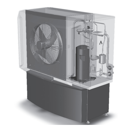
1167 Figure 1: DHP-AX, dimensions and connections. Position Name Supply line heating system, DHP-AX 6, 8, 10: 22 Cu, DHP-AX 12: 28 Cu Return line heating system, DHP-AX 6, 8, 10: 22 Cu, DHP-AX 12: 28 Cu 3.1.2 Components The component image below shows diagrammatically how the heat pump looks inside. There may be differ- ences between different versions. -
Page 9: Technical Data Dhp-Ax
Technical data DHP-AX Air to water heat pump DHP-AX Refrigerant Type R407C R407C R407C R407C Amount Test pressure Design pressure Compressor Type Scroll Scroll Scroll Scroll Electrical data Main supply Volt 3-N~50Hz Rated power compressor Rated power, fan Start current... -
Page 10: Supplied Contents
UR1-025TC-13 12kW UR1-025TC-16 Blue 400 mm 3.3.3 Packaging Quantity Name Figure 3: Necessary service space for DHP-AX. Dirt filter with shut-off DN25 Outdoor sensor Safety valve 1,5 bar 1/2” Front cover Control centre 4 m Supply line sensor 3.3.4 Document set... -
Page 11: Unpacking And Installation
Unpacking and installation Positioning the heat pump When positioning the heat pump, note the following: Assembling the stand (accessory) The heat pump must be positioned some dis- NOTE! Only place the heat pump on its short tance away from the ground as the defrost side as shown in the figure below, otherwise function can cause ice build-up. -
Page 12: Piping Installation
Piping installation Buffer tank The buffer tank equalises the temperature to the heating system during operation and after defrosting. NOTE! To prevent leaks, ensure that there are no stresses in the connecting pipes! BB E B T he recommendation for the volume is that 10 litres/kW installed heat pump output for heat pumps with heater and 20 litres/kW for heat NOTE! It is important that the heating system... -
Page 13: Connecting Cold And Hot Water Lines
Heating circuit 2 Heating circuit 1 1 12 82 80 Cold water Hot water 5.1.1 DHP-AX, VL system Connecting the heating system sup- ply and return lines Figure 7: General connection diagram. Position Name BB E B DHP-AX heat pump... -
Page 14: Electrical Installation
Electrical Installation 6.1.3 Electrical components in 230V 1N control centre BB B B Electrical current! The terminal blocks are live and can be highly dangerous due to the risk of electric shock. All power supplies must be iso- lated before electrical installation is started. The heat pump is connected internally at the factory, for this reason electrical installation consists mainly of the connection of the power supply. -
Page 15: Connecting The Power Supply
When the cable is connected to the terminal block a To measure the outdoor temperature as accurately screwdriver is used to open the terminal block, see fig- as possible, the sensor must be positioned 2/3 of the ure below. way up the facade on houses up to three storeys high. For higher buildings, the sensor should be positioned between the second and third storeys. -
Page 16: Evu Function
Checking the installation In the event of a surplus of heat the conditions are the opposite: NOTE! Read the safety instructions! ROOM Increased Actual room Set point for FACTOR room tempe- temperature, supply line, The installation may only be commissioned if rature, °C °C °C... -
Page 17: Manual Test
8.3.7 Sensor calibration To see the locations of the sensors, see section 5.2.1 DHP-AX, VL system for the externally located sensors and section 11.2.1 Heating function for the internally located sensors. BB E B F or further information about the heat pump’s control system, see section 12 Control panel. -
Page 18: Reinstalling Panels
9.2.1 Hot water Follow the instructions below to perform a calibration. Detach and remove any insulation by the sensor to be calibrated. NOTE! If an external water heater is to be installed, it must be activated in the SERVICE Connect a thermometer by the sensor. menu. -
Page 19: Customer Information
Customer information After installation and test operation, the customer must be informed about their new heat pump installation. Below is a checklist regarding the information that the installer must give the customer: The model of the heat pump that has been installed Run through the User manual and show what it con- tains Describe the various operating modes and what they... -
Page 20: Service Instructions
Service instructions 20 – Service VMBMH302... -
Page 21: The Heat Pump
The heat pump 11.1 Function description A heat pump utilises the free energy from the sun and that is found in a natural heat source, such as rock, ground, ground water or air. The heat pump can be compared to a reversed refrigerator; in a refrigerator heat is transferred from the inside of the refrigerator to the outside, whereas in a heat pump, the stored solar energy that is stored in a heat source is transferred to the inside of the house. -
Page 22: Heating And Defrost Functions
11.2.1 Heating DHP-AX is a heat pump that can produce heating for houses and water heaters. Hot water production is active all year round but during the summer heat production to the house is stopped when the outdoor temperature reaches the value for HEAT STOP. -
Page 23: Components
During operation the air heat exchanger is cooled by the energy exchange at the same time as the humid- ity causes it to become covered in frost. DHP-AX has an automatic function to defrost the air heat exchanger using the produced heat energy. If necessary, a defrosting sequence starts which means the following:... -
Page 24: Auxiliary Heat
11.4 Auxiliary heat Auxiliary heater is an option for DHP-AX and consists of an immersion heater, which is located on the supply pipe ahead of the exchange valve. The auxiliary heater, which is supplied as an accessory has an integrated power control and is controlled by a potential free output from the heat pump. - Page 25 At outdoor temperatures colder than 0°C, supply water hotter than 40°C is sent out to the heating system and at outdoor temperatures greater than 0°C, supply water cooler than 40°C is sent out. Supply temperature Maximum supply tem- perature Outdoor temperature Figure 20: Increasing or reducing the CURVE changes the slope of the curve If you increase the CURVE value, the heat curve will become steeper and when you reduce it, it will become flatter.
- Page 26 Supply temperature Local higher supply temperature at -5° Outdoor temperature Figure 22: The adjusted curve at -5°C Sometimes, at outdoor temperatures between -5°C and +5°C, part of the heat curve may need adjusting if the indoor temperature is not constant. For this reason, the control system includes a function adjusting the curve at three outdoor temperatures: -5°C, 0°C, +5°C.
- Page 27 The integral value is a measurement of the surface under the time axle and is expressed in degree minutes. The figure below shows the factory settings for the integral values that the heat pump has. When the integral value has reached the set value for INTEGRAL A1, the compressor starts and if the integral value does not drop but continues to rise, the auxiliary heater starts when the integral value has reached the set value for INTEGRAL A1+A2.
- Page 28 11.5.9 DEFR CURVE To start defrosting the outdoor unit, the control system makes a calculation using the temperature of the incoming refrig- erant and the outdoor temperature. What guides the calculation is a linear defrosting curve that can be set so that the heat pump and outdoor unit work optimally.
-
Page 29: Control Panel
Control panel 12.1 Function description The heat pump has an integrated control system that is used to automatically calculate the heat demand in the house where the heat pump is installed and to ensure that the correct amount of heat is produced and emitted where neces- sary. -
Page 30: Display
The indicator at the bottom of the control panel has two modes: L it continuously, the heat pump has power and is ready to produce heat or hot water F lashing, means an active alarm NOTE! During a service that consists of replacing the display card, all heat pump settings are lost. If possible, note all specific settings for the customer’s heat pump before replacement. - Page 31 Symbol Meaning DEFROST Displayed when defrosting is active. Displayed when the fan is active. 12.2.4 Operational information Shows text information about the heat pump. Message Meaning ROOM Shows the set ROOM value. Standard value: 20°C. If the accessory room sensor is installed it shows the actual temperature and the indoor temperature within brackets.
-
Page 32: Menu Information
Menu information 13.1 INFORMATION menu This menu is used to change the heat pump’s operating modes and adjust the heat curve. History and operat- ing times can also be viewed here. Open the menu by pressing the left or right button. The sub menus always available in the INFORMATION menu are shown in the following table in bold: Menus in italics are only visible if the expansion card and certain sensors are installed. - Page 33 13.1.1 Sub menu INFORMATION -> OPERATION Used to select operating mode. Menu selection Meaning Factory setting The installation is off. This mode is also used to acknowledge (OFF) certain alarms. CANCEL = starting point, no changes made. To select OFF as operating mode, press the minus sign once to scroll down one step and press the right arrow once.
- Page 34 Menu selection Meaning Factory setting POOL Only appears if POOL is selected. The temperature in the pool 20°C (Expansion card) is controlled by a separate sensor regardless of the heating and (interval: , 5°C / 40°C) hot water system. Only appears if POOL is selected. In simple terms, the POOL 2°C (interval: 1°C / 10°C) POOL HYSTERESIS (Expansion card)
- Page 35 13.1.5 Sub menu INFORMATION -> OPERAT. TIME Used to show the operating time for each component. Time given in hours. Menu selection Meaning Factory setting HEAT PUMP Compressor operating time for both heating and hot water pro- duction. AUX. HEAT 1 Operating time auxiliary heat step 1.
-
Page 36: Service Menu
13.2 SERVICE menu This menu is for use during installation and service to optimise and adjust the operation of the heat pump. Open the menu by holding the left button in for five seconds. The sub menus always available in the SERVICE menu are shown in the following table in bold: Menus in italics are only visible if the expansion card is installed. - Page 37 13.2.1 Sub menu SERVICE -> HOT WATER Used to change the settings for hot water production. Menu selection Meaning Factory setting START Start temperature for hot water production. Shows the actual weighted hot water temperature and the value within brackets (interval: , 30°C / 55°C) indicates the start temperature.
- Page 38 Menu selection Meaning Factory setting HYSTERESIS If the difference between the actual supply temperature and 20°C the calculated supply temperature is too great (see section 11.5 (interval: 5°C / 30°C) Important parameters), either the integral value is set to start value A1 + A2 (starts the auxiliary heater) or the value is set to 0 (stops the auxiliary heater ).
- Page 39 13.2.5 Sub menu SERVICE -> INSTALLATION Used for settings that are set during installation. Menu selection Meaning Factory setting ENGLISH Language setting for the control system. ENGLISH The button sequence that is to be pressed to access this menu to (ÈEŠTINA, change language is shown here: POLSKI,...
- Page 40 Menu selection Meaning Factory setting VERSION Shows the software version which is stored on the display card respectively the I/O-card. DISPLAY: V n.n I/O-CARD: V n.n LOG TIME Time interval between collection points of temperature history 1M (interval: 1M / 60M) in minutes.
- Page 41 VMBMH302 Service – 41...
-
Page 42: Noise Information
Noise information 14.1 Flexible hoses All pipes should be routed in such a way that vibrations cannot be transmitted from the heat pump through the piping and out into the building. This also applies to the expansion pipe. To avoid the transmission of vibrations, we recommend that flexible hoses are used for the supply line and return line on both the heating system and brine system sides. -
Page 43: Preventative Measures
14.2 Preventative measures Some of the following points can also be used when troubleshooting. D o not install heat pumps on walls adjoining bedrooms. E nsure that all pipes are elastically suspended, with mountings as illustrated or similar. This is so that the rubber (or similar material) compresses 1–2 mm under vibration. -
Page 44: Troubleshooting
Troubleshooting 15.1 Alarm Shown in display in the event of an alarm. To reset alarms 1-5, set the operating mode to OFF or cut the power supply. Message Meaning HIGH PRESSURE ERROR Tripped high pressure switch. Compressor stopped. No hot water production. LOW PRESSURE ERROR Tripped low pressure switch. -
Page 45: Measurement Points
15.2 Measurement points Conversion table for sensors When reading the resistance of the sensors, the sensor leads must first be disconnected from the control equipment. Outdoor sensor Other sensors Disconnect the sensor cable at the I/O Kiloohm, card. °C °C kÙ... -
Page 46: Operational Problems
T he tables in the following section apply to all types of heat pump and collector solutions. This means that cer- tain information does not apply to DHP-AX. The tables have the most probable and most common causes of the problem listed first. When troubleshoot- ing the cause of a problem start with the first cause and go down the list. - Page 47 Cause Troubleshooting Remedy 8. Incorrect mix of anti-freeze, Check the freezing point of the mix using If the mixture is not in accordance with the concentration must be in a refractometer. the instructions, it must be remixed in accordance with instructions. an external container.
- Page 48 Cause Troubleshooting Remedy 15. Blocked evaporator on the Using manometer apparatus and ther- If the evaporator is thought to be block- refrigerant side. mometer, check that the unit’s overhea- ed by oil for example, try blowing nitro- ting is correct for the specific refrigerant. gen through it to release the oil.
- Page 49 Cause Troubleshooting Remedy 9. External system shunt that clo- Check for shunts or valves in the system, Always ensure that there is a sufficiently ses on time setting. which are timer-controlled, that close large water volume for the heat pump to down the entire or too large a part of the work against, i.e.
- Page 50 Problem – Alarm MS (motor protection) Cause Troubleshooting Remedy 1. Phase drop or blown fuse. Check that all phases are present on the If any of the phases are not present, terminal block for incoming supply. If check backwards towards the building’s not, check the fuses in the cabinet.
- Page 51 Problem – Incorrect phase sequence Cause Troubleshooting Remedy The incoming phases have the • If the text ERR PHASE SEQ. appears in If the phases are in the incorrect order, incorrect sequence (only applies the display when the heat pump is powe- switch two incoming phases at the main to 3-phase heat pumps).
- Page 52 Cause Troubleshooting Remedy 2. Brine temperature too low. Check the set value on ALARM BRINE in The alarm is triggered when the tempera- the heat pump’s control computer. ture on BRINE OUT is as low or lower than the set value on ALARM BRINE. In the fac- tory setting this function is inactive.
- Page 53 Cause Troubleshooting Remedy 4. Overheating too high. Using manometer apparatus and ther- If the overheating reading does not cor- mometer check what the overheating respond with the instructions for the reading of the unit is. specific refrigerant, adjust the expansion valve until the correct value is obtained.
- Page 54 Cause Troubleshooting Remedy 11. Leak at soldered joint on Locate the leak. If there is a leak at the soldered joint, water heater. replace the water heater. 12. Associated leak on the water • Establish whether water continuously If the water heater has a leak, replace it. heater.
- Page 55 Problem – Loud compressor noise Cause Troubleshooting Remedy 1. Phase drop. 1. Check that there is 400 V between Check where the phase drop is and rec- incoming phases on the heat pump. tify. The compressor attempts to start or operates on two phases. 2.
-
Page 56: Hot Water
15.4.4 Hot water Problem – Temperature and/or quantity Cause Troubleshooting Remedy 1. Defective 3-way valve motor. Check the function of the 3-way valve, If the motor is defective, replace it. that it runs between the end positions by running a manual test. 2. - Page 57 Cause Troubleshooting Remedy 10. Heat loss in the hot water Open the hot water tap, read off the tem- If any problems occur during trou- pipe. perature on the outgoing hot water pipe bleshooting as per the points, carry out from the heat pump and the temperature corrective actions.
- Page 58 Cause Troubleshooting Remedy 6. The heat pump has stopped • Check what the MAX RETURN value is If the MAX RETURN value is not adjusted on HIGH RETURN. set at in the heat pump’s control com- for the system according to the trou- puter.
- Page 59 Cause Troubleshooting Remedy 12. Changed conditions • If the heat pump has been dimensioned If the heat pump cannot cope with the for a certain demand and this demand is demand, replace it with one with a hig- Have you increased your heating increased, the heat pump might not be her output or supplement it with a hig- and/or hot water demand?
- Page 60 Problem – irregular indoor temperature Cause Troubleshooting Remedy 1. The heat pump’s control com- Check the ROOM and CURVE, MIN, MAX Adjust incorrect values in the heat pump’s puter is not set/adjusted to the CURVE5, CURVE0, CURVE-5 and HEAT control computer. customer’s requirements/wishes.
- Page 61 Problem – Runs on electric heating element Cause Troubleshooting Remedy 1. Operating mode AUX. HEATER If this operating mode is selected, the aux- If AUX. HEATER mode is selected and you is selected. iliary heater is used for heating and hot no longer want it, change to AUTO, the water production, not the compressor.
- Page 62 Problem – The auxiliary heater is in operation but not the compressor Cause Troubleshooting Remedy 1. Operating mode AUX. HEATER If this operating mode is selected, the If AUX. HEATER mode is selected and you is selected. auxiliary heater is used for heating and hot no longer want it, change to AUTO, the water production, not the compressor.
- Page 63 Cause Troubleshooting Remedy 7. The compressor runs backwards. • If the text ERR PHASE SEQ. appears in the If the phases are in the incorrect order, The incoming phases have the display when the heat pump is powered, switch two incoming phases at the main incorrect sequence (only applies (only appears in the first 10 minutes) this terminal block and recheck according to...
- Page 64 Cause Troubleshooting Remedy 7. The heat pump has stopped on • Check what the MAX RETURN value is set If the MAX RETURN value is not adjusted for HIGH RETURN. at in the heat pump’s control computer. It the system according to the troubleshooting must be adjusted to the unit’s maximum window, adjust it.
- Page 65 Cause Troubleshooting Remedy 12. Overfilled refrigerant circuit. Using manometer apparatus and ther- Follow the correct procedure (depending mometer, check that the unit’s overhea- on type of refrigerant) to add the correct ting is correct for the specific refrigerant. amount of refrigerant. 13.
- Page 66 Cause Troubleshooting Remedy 5. Changed conditions Have you • If the heat pump has been dimensioned If the heat pump cannot cope with the increased your heating and/or for a certain demand and this demand is demand, replace it with one with a hig- hot water demand? increased, the heat pump might not be her output or supplement it with a hig-...
- Page 67 15.4.7 Outdoor unit Problem – Noise/loud noise Cause Troubleshooting Remedy 1. Positioning the outdoor unit. Determine whether the outdoor unit can When positioning the outdoor unit, its be moved to a more suitable location. direction does not affect its performance. The outdoor unit does not need to be positioned as close to the heat pump as necessary, it can be positioned as far as...
- Page 68 68 – Service VMBMH302...
- Page 69 VMBMH302 Service – 69...
- Page 70 VMBMH302...
Need help?
Do you have a question about the DHP-AX and is the answer not in the manual?
Questions and answers