Danfoss DHP-A User Manual
Hide thumbs
Also See for DHP-A:
- Installation instructions manual (127 pages) ,
- Service instructions manual (86 pages) ,
- Installation manual (64 pages)

Related Manuals for Danfoss DHP-A


Summary of Contents for Danfoss DHP-A
- Page 1 User manual DHP-A DHP-A Opti DHP-AL DHP-AL Opti DHP-C DHP-H DHP-H Opti DHP-H Opti Pro DHP-L DHP-L Opti DHP-L Opti Pro VUBMA902...
- Page 2 Danfoss A/S reserves the right to make changes to components and specifications without prior notice. © 2010 Danfoss A/S. The Swedish language is used for the origi- nal instructions. Other languages are a translation of the original instructions. (Directive 2006/42/EC)
-
Page 3: Table Of Contents
Contents Foreword..............................3 Safety precautions..........................4 Installation and maintenance......................4 System modifications..........................5 Safety valve..............................5 About your heat pump........................6 Control system............................. 11 Keypad............................... 11 Indicator..............................11 Display................................ 12 Main Menu..............................14 Settings and adjustments........................ 15 Setting operating mode........................15 Adjusting the indoor temperature.................... -
Page 5: Foreword
We thank you for the confidence that you have shown in us by buying a heat pump from Danfoss. We hope that you will benefit from it for many, many years to come. -
Page 6: Safety Precautions
Safety precautions DANGER! The front of the heat pump must only be opened by authorised service technicians. Caution! This product is not intended for persons (including children) with reduced physical, sensory or psychological capacity, or who do not have knowledge or experience, unless supervised or they have received instructions on how the apparatus functions from a safety qualified person. -
Page 7: System Modifications
DANGER! Only authorized refrigeration technicians may work on the refrigerant circuit. System modifications Only authorized installers may carry out modifications on the following components: • The heat pump unit • The pipes for the refrigerant, brine, water and power • The safety valve Do not carry out construction installations that may affect the opera- tional safety of the heat pump. -
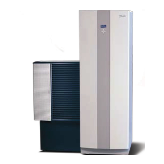
Page 8: About Your Heat Pump
Control equipment Outdoor and defroster function Applies to DHP-A. DHP-A are equipped with an outdoor unit that uses air as a heat source down to -20°C. The outdoor unit has a coil where brine recovers energy 6 – User manual VUBMA902... - Page 9 During operation the coil is cooled by the energy exchange at the same time as the humidity causes it to become covered in frost. DHP-A has an automatic function to defrost the coil using the produced heat energy. If necessary, a defrosting sequence starts which means the following: •...
- Page 10 Water heater Danfoss heat pumps DHP-H and DHP-C are supplied with an integrated 180 litre water heater. They are equipped with a TWS coil that means more effective heat transfer and efficient layering of the water in the water heater.
-
Page 11: Auxiliary Heat
Step 4 Step 5 Step +4 Step +5 The two power steps, step 4 and step 5 for DHP-A cannot be activated when the compressor is running. Auxiliary heater step: +4 and +5 can be User manual VUBMA902 – 9... - Page 12 connected when the compressor is running and must only be selected on the condition that the building where the heat pump is installed has a large heating demand and the building’s electric installation is suita- ble for high current consumption. In the event of an alarm, the auxiliary heater engages automatically on the condition that operating mode AUTO is selected and that at least one additional step is permitted.
-
Page 13: Control System
Control system The heat pump has an integrated control system which automatically calculates the heat demand in the house to ensure that the correct amount of heat is produced and emitted where necessary. The control panel is operated using a keypad and information is shown in a display and by an indicator. -
Page 14: Display
(anti-legion- ella function). SQUARE Either indicates that the operating pressure switch has deployed, or that the pressure pipe temperature has reached its maximum temperature. DEFROST Displayed when defrosting is active (applies to DHP-A). 12 – User manual VUBMA902... - Page 15 Symbol Meaning Displayed when the fan is active (applies to DHP-A). L = Low speed, H = High speed COOLING Displayed if cooling is produced. A = Active cooling. The following operating information may also appear: Message Meaning ROOM Shows the set ROOM value. Standard value: 20°C.
-
Page 16: Main Menu
Main Menu The display's INFORMATION menu is used to set and adjust the heat pump functions and is opened by pressing the left or right buttons. The menu has the following appearance: Sub-menus Return INFORMATION OPERAT. Cursor HEAT CURVE TEMPERATURE If an arrow is shown, it indi- OPERAT. -
Page 17: Settings And Adjustments
Settings and adjustments An authorized installer carries out the basic settings of the heat pump at installation. A number of settings and adjustments that you can carry out yourself are described below. Note! Before changing the control computer’s settings, first find out what these changes mean. -
Page 18: Adjusting The Indoor Temperature
Operating Meaning mode ADD. HEATER The control system only permits the auxiliary heater to be in operation. HOT WATER In this mode the heat pump only produces hot water, no heat goes to the heating system. Caution! If the operating mode OFF or HOT WATER is to be used for long periods during the winter, the water in the heating system in the heating system must be drained, otherwise there is a risk of frost damage. -
Page 19: Parameter Description
This is the most energy and cost efficient way to set the indoor tempera- ture and should therefore be used for long term temperature settings. Supply temperature (°C) Maximum setpoint value° Outdoor temperature (°C) 0°C °Set value (standard 40°C) -2 0 The following parameters can be adjusted: Parameter Description... - Page 20 Adjust the heat curve in the HEAT CURVE menu as follows: Open the menu HEAT CURVE. in the INSTAL- HEAT CURVE CURVE 40˚C LATION menu. 22˚C 70˚C Mark desired parameter using + or – button. CURVE 5 0˚C CURVE 0 0˚C Open the parameter by pressing the right CURVE -5...
-
Page 21: Reading Off Temperatures
Reading off temperatures The set point value for the supply line and the TEMPERATURE OUTDOOR 0˚C max value of the return line is shown within ROOM 20˚C brackets The max value indicates the tempera- SUPPLY LINE 38(70)˚C RETURN LINE 34(48)˚C ture at which the compressor is stopped. - Page 22 Press either the right or left button once to open the INFORMA- TION menu. The cursor is in the OPERATION menu option. Press the down button to move the cursor to the DEFROST menu option. Open the menu by pressing the right button once. Press the down button to move the cursor to the MANUAL DEFROST menu option.
-
Page 23: Regular Checks
Regular checks Checking operation During normal operation, the alarm indicator lights green continuously to show that everything is OK. When the alarm is triggered, it flashes green at the same time as a text message is shown in the display. Regularly check the alarm indicator to ALARM ensure that the installation is working... -
Page 24: Check The Water Level In The Heating Circuit
Message Meaning ERR PHASE SEQ. Can be displayed in conjunction with interference in the mains network, for example after a temporary power cut. Reset the alarm as follows. If necessary switch off the power supply for a minute or two. Other alarm mes- Reset the alarm as follows. -
Page 25: Checking Safety Valves
For DHP-A with pressurized brine circuit the manometer on the expan- sion tank must show approx. 1.0 bar. Always call your installer for refilling of refrigerant. -
Page 26: In The Event Of Leakage
In the event of leakage In the event of leakage in the hot water pipes between the heat pump and water taps, close the shut-off valve on the cold water inlet immedi- ately. Then contact your installer. In the event of leakage in the brine circuit, turn off the heat pump and call your installer immediately. - Page 27 Remove the strainer. Rinse the strainer. Reinstall the strainer. Check that the o-ring on the cover is not damaged. Screw the cover back into place. Turn the shut-off cock to the open position. For the brine circuit strainer - reinstall the insulation around the filler cock.
-
Page 28: Default Setting In The Control Computer
Default setting in the control computer The first column in the table below shows the parameters that can be adjusted by the User. The second column shows settings made at the factory, and the third column the settings made by the installation con- tractor in connection with installation of the heat pump. -
Page 29: References
References Check list Installed model: ..............• Setting up Surface adjustment • Piping installation Leak test Bleeding Open radiator valves Function test safety valve • Electrical Installation Direction of rotation of the compressor Outdoor sensor Accessories: ............... • Brine installation Type of brine: ............ -
Page 30: Installation Carried Out By
Installation carried out by: Piping installation Date ............Company ............Name ............Tel. No............Electrical Installation Date ............Company ............Name ............Tel. No............System adjustment Date ............Company ............Name ............Tel. No............28 – User manual VUBMA902... - Page 31 VUBMA902...
Need help?
Do you have a question about the DHP-A and is the answer not in the manual?
Questions and answers