Table of Contents
Advertisement
Available languages
Available languages
Quick Links
Advertisement
Table of Contents

Related Manuals for RCF QPS 10K


Summary of Contents for RCF QPS 10K
- Page 1 OWNER’S MANUAL MANUALE UTENTE QPS 10K QPS 6.0K FOUR-CHANNEL POWER AMPLIFIERS...
-
Page 3: Table Of Contents
CONTENTS CONTENTS .................................. 3 ENGLISH SAFETY PRECAUTIONS AND GENERAL INFORMATION ....................4 DESCRIPTION ................................8 UNPACKING AND INSTALLATION ..........................8 FRONT PANEL ................................9 REAR PANEL ................................10 OPERATION MODES ..............................13 SPEAKON CONNECTORS WIRING ..........................18 COOLING REQUIREMENTS ............................18 ITALIANO AVVERTENZE PER LA SICUREZZA .......................... -
Page 4: Safety Precautions And General Information
RCF S.p.A. will not assume any responsibility for the incorrect installation and / or use of this product. - Page 5 (wall, ceiling, structure, etc.), and the components used for attachment (screw anchors, screws, brackets not supplied by RCF etc.), which must guarantee the security of the system / installation over time, also considering, for example, the mechanical vibrations normally generated by transducers. To prevent the risk of falling equipment, do not stack multiple units of this product unless this possibility is specified in the user manual.
- Page 6 IMPORTANT NOTES To prevent the occurrence of noise on line signal cables, use screened cables only and avoid putting them close to: Equipment that produces high-intensity electromagnetic fields Power cables Loudspeakers lines WARNING! CAUTION! To prevent the risk of fire or electric shock, never expose this product to rain or humidity.
- Page 7 Modifications: Any modifications made to this device that are not approved by RCF may void the authority granted to the user by the FCC to operate this equipment.
-
Page 8: Description
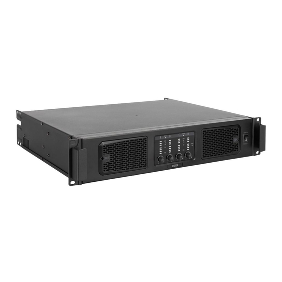
RCF S.p.A. thanks you for purchasing this product, which has been designed to guarantee reliability and high performance. DESCRIPTION QPS Series offers a range of four-channels professional amplifiers that combines high quality performance and reliability with the latest power amplifications technologies. This high value design offers, in compact 2 rack unit space, the sound quality and the durability of class HD amplifiers with the innovation of the latest power devices available: QPS 10K can deliver up to 4 x 2500 W @ 2 ohm;... -
Page 9: Front Panel
FRONT PANEL POWER SWITCH. Before switching the amplifier on, check all cables and turn fully counterclockwise all the four channel level controls [4]. Removable grill with dust protection foam. POWER LED. GREEN. When lit, the amplifier is switched on. GAIN CONTROLS (for each channel), to adjust the output level of the respective amplifier channels. Turn clockwise to increase the output level (0 dB = max. -
Page 10: Rear Panel
LEDs BAR (for each channel). GREEN. When lit, it indicates the signal presence at the respective input. PRES Signal level is represented by the first three leds in the lower part of the bar. YELLOW. It blinks when the signal level reaches the clipping point, causing the limiter intervention CLIP on the respective channel. - Page 11 DIP-SWITCH SETTINGS AREA. VPK - VOLTAGE PEAK LIMITER setting (for each channel). Three dip-switches allow to set the maximum output voltage peak for each channel among eight values. it makes possible to reduce the channel power according to connected speakers. Max power value can be calculated using the formula: 4 INDEPENDENT CHANNELS CHANNELS BRIDGED 150 V...
- Page 12 BRIDGE LEDs (A+B) and (C+D). When lit channels A and B (and/or C+D) are bridged (see BRIDGE switches). [13] [11] STEREO / PARALLEL SWITCH. See the ‘Operation modes’ manual section. [14] Important: make sure the amplifier is turned off before setting this switch. SWITCH POSITION MODE FUNCTION...
-
Page 13: Operation Modes
OPERATION MODES FOUR INDEPENDENT CHANNELS Make sure the amplifier is switched off before setting: BRIDGE A+B switch to OFF; BRIDGE C+D switch to OFF; switch to STEREO. [14] All the four channels are independent, and each front panel level control affects its respective speakers’ output. This mode can be used to implement four mono channels or two stereo channels configurations. - Page 14 ONE BRIDGED OUTPUTS PAIR AND TWO INDIPENDENT CHANNELS Make sure the amplifier is switched off before setting: BRIDGE A+B switch to ON; BRIDGE C+D switch to OFF; switch to STEREO. [14] CHANNELS A AND B: these channels are bridged and work with the same input signal (channel A input). The result is a doubling of the output voltage in order to get a double power (on a double impedance load).
- Page 15 TWO BRIDGED OUTPUTS PAIRS Make sure the amplifier is switched off before setting: BRIDGE A+B switch to ON; BRIDGE C+D switch to ON; switch to STEREO. [14] All channels are bridged (two pairs): the result is a doubling of the output voltage in order to get a double power (on a double impedance load).
- Page 16 SAME INPUT SIGNAL TO ALL THE FOUR CHANNELS Make sure the amplifier is switched off before setting: BRIDGE A+B switch to ON; BRIDGE C+D switch to ON; switch to PARALLEL. [14] In PARALLEL mode connect input A or input C only. Do not used them simultaneously. This mode can be used to send the same input signal to all the four speakers’...
- Page 17 SAME INPUT SIGNAL TO BRIDGED OUTPUTS PAIRS Make sure the amplifier is switched off before setting: BRIDGE A+B switch to ON; BRIDGE C+D switch to ON; switch to PARALLEL. [14] In PARALLEL mode connect input A or input C only. Do not used them simultaneously. All channels are bridged (two pairs): the result is a doubling of the output voltage in order to get a double power (on a double impedance load).
-
Page 18: Speakon Connectors Wiring
SPEAKON CONNECTORS WIRING COOLING REQUIREMENTS QPS 10K and QPS 6.0K have a forced air cooling system to maintain a low operating temperature. Make sure there is enough space in the front (and all around) of all amplifiers. If amplifiers are rack-mounted, do not use doors or covers on the front and the rear of rack cabinets. -
Page 19: Avvertenze Per La Sicurezza
RCF S.p.A. non si assume alcuna responsabilità per l’installazione e / o l’uso errati di questo prodotto. - Page 20 Verificare inoltre l’idoneità della superficie di supporto a cui è ancorato il prodotto (parete, soffitto, struttura, ecc.) a dei componenti utilizzati per il fissaggio (tasselli, viti, staffe non fornite da RCF ecc.) che devono garantire sicurezza del sistema / installazione nel tempo, anche considerando, ad esempio, le vibrazioni meccaniche normalmente generate dai trasduttori.
- Page 21 NOTE IMPORTANTI Per evitare il verificarsi di disturbi sui cavi di segnale in linea, utilizzare solo cavi schermati ed evitare di avvicinarli a: Apparecchiature che producono campi elettromagnetici ad alta intensità Cavi di alimentazione Linee di altoparlanti ATTENZIONE! CAUTELA! Per evitare il rischio di incendi o scosse elettriche, non esporre mai questo prodotto a pioggia o umidità.
- Page 22 È probabile che il funzionamento di questa apparecchiatura in un'area residenziale provochi interferenze dannose, nel qual caso l'utente dovrà correggere l'interferenza a proprie spese. Modifiche: qualsiasi modifica apportata a questo dispositivo che non sia approvata da RCF può annullare l'autorizzazione concessa all'utente dalla FCC di utilizzare questa apparecchiatura.
-
Page 23: Descrizione
RCF S.p.A. Vi ringrazia per l’acquisto di questo prodotto, realizzato in modo da garantirne l’affidabilità e prestazioni elevate. DESCRIZIONE La serie QPS offre una gamma di amplificatori professionali a quattro canali che unisce alte prestazioni e affidabilità, con le più nuove tecnologie nel campo dell’amplificazione. Grazie ad un design orientato all’efficienza, gli amplificatori della serie offrono la qualità... -
Page 24: Pannello Frontale
PANNELLO FRONTALE INTERRUTTORE PRINCIPALE. Prima di accendere l'amplificatore, controllare tutte le connessioni e ruotare completamente in senso antiorario i controlli di livello di tutti i quattro canali. Griglie rimovibili con spugna antipolvere. POWER LED. VERDE. Indica l'accensione dell'amplificatore. CONTROLLI DI GUADAGNO (uno per ogni canale) per la regolazione del livello d'uscita dei rispettivi canali dell'amplificatore. -
Page 25: Pannello Posteriore
BARRA LED (per ciascun canale). VERDE. Quando acceso, indica la presenza del segnale nel rispettivo ingresso. Il livello del segnale è PRES rappresentato dai primi tre led nella parte inferiore della barra. GIALLO. Lampeggia quando il livello del segnale raggiunge il il livello massimo prima della CLIP saturazione, causando l’intervento del limitatore interno del rispettivo canale. - Page 26 SETTAGGI TRAMITE DIP-SWITCH. LIMITER HARDWARE - VPK (per ciascun canale). I tre dip-switch permettono l’impostazione della massima tensione di picco d’uscita di ciascun canale, tra otto valori. In altre parole, è possibile depotenziare il canale in base ai diffusori acustici collegati. Il valore massimo di potenza può essere calcolato con la formula: CANALI INDIPENDENTI CANALI A PONTE 150 V...
- Page 27 LED BRIDGE (A+B) e (C+D). Se accesi i canali A e B (e/o C e D) sono messi a ponte (vedere il punto : Selettori [13] [11] BRIDGE). SELETTORE STEREO / PARALLEL. Vedere la sezione del manuale “Modi di funzionamento”. [14] Importante: assicurarsi che l'amplificatore sia spento prima di effettuare la selezione.
-
Page 28: Modi Di Funzionamento
MODI DI FUNZIONAMENTO QUATTRO CANALI INDIPENDENTI Assicurarsi che l'amplificatore sia spento prima di impostare: il selettore BRIDGE A+B su OFF; il selettore BRIDGE C+D su OFF; il selettore su STEREO. [14] Tutti i quattro canali sono completamente indipendenti ed ogni controllo di livello (sul pannello frontale) agisce (solo) sulla rispettiva uscita altoparlanti. - Page 29 UNA COPPIA DI CANALI A PONTE E DUE CANALI INDIPENDENTI Assicurarsi che l'amplificatore sia spento prima di impostare: il selettore BRIDGE A+B su ON; il selettore BRIDGE C+D su OFF; il selettore su STEREO. [14] CANALI A e B: questi sono messi a ponte e hanno in comune lo stesso segnale d'ingresso (quello del canale A). Questo comporta un raddoppio della tensione d'uscita per ottenere una potenza doppia (su un carico avente impedenza doppia).
- Page 30 DUE COPPIE DI CANALI A PONTE Assicurarsi che l'amplificatore sia spento prima di impostare: il selettore BRIDGE A+B su ON; il selettore BRIDGE C+D su ON; il selettore su STEREO. [14] Tutti i canali sono a ponte (due coppie): questo comporta un raddoppio della tensione d'uscita per ottenere una potenza doppia (su un carico avente impedenza doppia).
- Page 31 UN UNICO SEGNALE COMUNE A TUTTI I QUATTRO CANALI Assicurarsi che l'amplificatore sia spento prima di impostare: il selettore BRIDGE A+B su ON; il selettore BRIDGE C+D su ON; il selettore su PARALLEL. [14] Con modalità PARALLEL collegare solo l’ingresso A oppure l’ingresso C. Non utilizzare i due ingressi simultaneamente.
- Page 32 UN UNICO SEGNALE COMUNE A COPPIE DI CANALI A PONTE Assicurarsi che l'amplificatore sia spento prima di impostare: il selettore BRIDGE A+B su ON; il selettore BRIDGE C+D su ON; il selettore su PARALLEL. [14] Con modalità PARALLEL collegare solo l’ingresso A oppure l’ingresso C. Non utilizzare i due ingressi simultaneamente.
-
Page 33: Cablaggio Dei Connettori Speakon
CABLAGGIO DEI CONNETTORI SPEAKON VENTILAZIONE Gli amplificatori QPS 10K and QPS 6.0K hanno un sistema di raffreddamento con ventilazione forzata per mantenere una bassa temperatura di funzionamento. Assicurarsi che vi sia spazio sufficiente sia davanti il pannello frontale sia tutt'intorno agli amplificatori. -
Page 34: Dimensions / Dimensioni
DIMENSIONS / DIMENSIONI... -
Page 35: Specifications / Specifiche Tecniche
SPECIFICATIONS / SPECIFICHE TECNICHE QPS 10K QPS 6.0K Amplifier specifications Amplifier Class: Number of channels: Power output per channel (@ 2 ohm): 2500W RMS 1500W Power output per channel (@ 4 ohm): 2200 W RMS 1300 W Power output per channel (@ 8 ohm):... - Page 36 RCF S.p.A. Via Raffaello Sanzio, 13 - 42124 Reggio Emilia – Italy 10307744 B Tel +39 0522 274 411 - Fax +39 0522 232 428 - e-mail: info@rcf.it - www.rcf.it...
Need help?
Do you have a question about the QPS 10K and is the answer not in the manual?
Questions and answers