Table of Contents
Advertisement
Advertisement
Table of Contents

Related Manuals for CAB EOS1


Summary of Contents for CAB EOS1
- Page 1 Operator's Manual Label Printer EOS1...
- Page 2 EOS1 / 300 PC Edition: 07/2011 - Art.-No. 9009088 Copyright This documentation as well as translation hereof are property of cab Produkttechnik GmbH & Co. KG. The replication, conversion, duplication or divulgement of the whole manual or parts of it for other intentions than its original intended purpose demand the previous written authorization by cab.
-
Page 3: Table Of Contents
Table of Contents Introduction ..................5 Product Description .................5 Instructions ..................5 Intended Use ...................6 Safety Instructions ................6 Environment ..................7 Installation ..................8 Device Overview ................8 Unpacking and Setting-up the Printer ..........9 Connecting the Device ..............10 2.3.1 Connecting to the Power Supply ..........10 2.3.2 Connecting to a Computer or Computer Network ......10 Switching on the Device .............. - Page 4 Table of Contents Licences ..................33 EC Declaration of Conformity ............33 FCC ....................34 GPL Code Statement ..............34 Index .....................35...
-
Page 5: Introduction
Introduction 1.1 Product Description The device is an industrial thermal transfer printer for printing labels and continuous media. 1.2 Instructions Important information and instructions in this documentation are designated as follows: Danger! Draws your attention to an exceptionally grave, impending danger to your health or life. -
Page 6: Intended Use
Introdcution 1.3 Intended Use • The device is manufactured in accordance with the current technological status and the recognized safety rules. However, danger to the life and limb of the user or third parties and/or damage to the device and other tangible assets can arise during use. -
Page 7: Environment
Introduction • Unauthorized interference with electronic modules or their software can cause malfunctions. • Other unauthorized work on or modifications to the device can also endanger operational safety. • Always have service work done in a qualified workshop, where the personnel have the technical knowledge and tools required to do the necessary work. -
Page 8: Installation
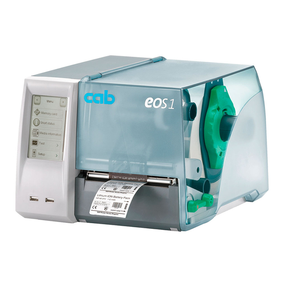
Installation 2.1 Device Overview 1 Cover 2 Margin stops 3 Roll retainer 4 Ribbon supply hub 5 Ribbon take-up hub 6 Belt roller 7 Print mechanics 8 Touchscreen display Fig. 1 Device with Tear-off Plate 9 Cutter or Perforation Cutter Fig. -
Page 9: Unpacking And Setting-Up The Printer
Installation 10 11 10 Label sensor 11 Printhead retainer with printhead 12 Guides 13 Knob for adjusting the guides 14 Knob for adjusting the label sensor 15 Lever for locking the printhead 16 Tear-off plate 17 Print roller Fig. 3 Print Mechanics 2.2 Unpacking and Setting-up the Printer ... -
Page 10: Connecting The Device
Installation 2.3 Connecting the Device 1 Power switch 2 USB master ports for keyboard, scanner, memory stick or service key 3 USB high-speed slave port 4 Ethernet 10/100 Base-T 5 Power connection jack Fig. 4 Connections 2.3.1 Connecting to the Power Supply The printer is equipped with a wide area power unit for a supply voltage of 100 V to 240 V. -
Page 11: Switching On The Device
Installation 2.4 Switching on the Device When all connections have been made: Switch the printer on at the power switch (1). The printer performs a system test, and then shows the system status Ready in the display. If an error occurs during the system test, the symbol , Critical fault and type of error are... -
Page 12: Control Panel
Control Panel 3.1 Structure of the Touchscreen Display Notice! It is advantageous, whenever possible, to make adaptations to various print jobs in the software. The touchscreen display (1) indicates the current status of the printer and the print job, indicates faults and shows the printer settings in the menu. -
Page 13: Symbols On The Start Display
Control Panel 3.3 Symbols on the Start Display Symbol Status Function Ready To offline menu Ready Feeds a blank label Ready After the end of a print job, reprint the last label Printing label Interrupt print job, printer goes into "Pause" state Pause Continue the print job, printer goes into "Printing label"... -
Page 14: Printer States
Control Panel 3.4 Printer States State Display Description Ready The printer is in the ready state and can receive data. Ready Printing Label Printing Label The printer is currently processing an active print job. and the number of the printed label in the print Data can be transmitted for a new job. -
Page 15: Loading Material
Loading Material 4.1 Loading Media from Roll Fig. 7 Loading Media from Roll 1. Turn ring (2) counterclockwise, so that the arrows points to the symbol and thus release the margin stop (1) from the roll retainer (4). 2. Load label roll (3) on the roll retainer (4) in such a way that the printing side of the labels is visible from above. -
Page 16: Loading Fanfold Labels
Loading Material 4.2 Loading Fanfold Labels Fig. 8 Loading Fanfold Labels 1. Position label stack (2) behind the printer. 2. Guide material below the roll retainer (1) to the printing unit. Ensure that the printing side of the labels is visible from above. 3. -
Page 17: Adjusting The Label Sensor
Loading Material 4.3 Adjusting the Label Sensor Notice! When the printer is delivered the label sensor is positioned in the middle of the paper feed. Thus, the label sensor must only be adjusted if: • material with reflex or cut-out marks, which are not in the middle, •... -
Page 18: Loading Transfer Ribbon
Loading Material 4.4 Loading Transfer Ribbon Fig. 10 Transfer Ribbon Feed Path Fig. 11 Guide Adjustment Notice! With direct thermal printing, do not load a transfer ribbon; if one has already been loaded, remove it. 1. Clean the printhead before loading the transfer ribbon ( 7.2 on page 23). 2. -
Page 19: Setting The Feed Path Of The Transfer Ribbon
Loading Material Attention! Guide transfer ribbon over the label sensor (7). 7. Secure starting end of the transfer ribbon to the ribbon core (3) using adhesive tape. Ensure counterclockwise rotation direction of the transfer ribbon take-up hub. 8. Turn transfer ribbon take-up hub (2) counterclockwise to smooth out the feed path of the transfer ribbon. -
Page 20: Cutter/Perforation Cutter
Option 5.1 Cutter/Perforation Cutter The cutter /perforation cutter contained in the contents of delivery must be mounted to the printer during the initial start-up. Fig. 13 Mount Cutter or Perforation Cutter 1. Put snap arm (5) of the cutter with the groove (4) first into the guide on the retainer (2). -
Page 21: External Supply Hub
Option 5.2 External Supply Hub Fig. 14 Load Material to External Supply Hub Mount External Supply Hub 1. Position External supply hub behind the printer. 2. Lift printer slightly and position ground plate (7) on both hooks (6) of the external supply hub. -
Page 22: Printing Operation
Printing Operation Attention! Printhead damage caused by improper handling! Do not touch the underside of the printhead with the fingers or sharp objects. Ensure that the labels are clean. The printer is ready for operation when all connections have been made and labels and the transfer ribbon have been loaded 6.1 Printing in Tear-off Mode After printing the label is torn-off manually. -
Page 23: Maintenance
Maintenance 7.1 Cleaning Instructions Danger! Risk of death via electric shock! Disconnect the printer from the power supply before performing any maintenance work. It is important to clean the thermal printhead regularly. This guarantees a consistently good printed image and reduces wear of the printhead. Otherwise, the maintenance is limited to monthly cleaning of the device. -
Page 24: Changing The Printhead
Maintenance Fig. 15 Printhead Line 1. Lift the printhead. 2. Remove labels and transfer ribbon from the printer. 3. Clean printhead line (1) with rubbing alcohol and a soft cloth. 4. Allow printhead to dry for 2–3 minutes before commissioning the printer. 7.3 Changing the Printhead Fig. -
Page 25: Cleaning Or Replacing The Print Roller
Maintenance 7.4 Cleaning or Replacing the Print Roller Accumulations of dirt on the print roller may impair the media transport and the print quality. Attention! Damage of the print roller. Do not use sharp objects (knives, screwdrivers, etc.) to clean the printhead. -
Page 26: Cleaning Cutter/Perforation Cutter And Replace Blades
Maintenance 7.5 Cleaning Cutter/Perforation Cutter and Replace Blades Warning! Disconnect printer from electrical outlet to prevent accidental blade movement. Warning! Risk of injury! The cutter blades are sharp! Notice! When cutting through the label material instead of the label gap remains of adhesive may accumulate on the blades. - Page 27 Maintenance Fig. 19 Replace Blades Fig. 20 Springs 4. If the blades are very dirty with residues of adhesive or if they are worn, change blades: Turn shaft (6) clockwise using a torx wrench TX10 until the gear racks (7) cannot engage anymore.
-
Page 28: Fault Correction
Fault Correction 8.1 Types of Errors The diagnostic system indicates on the touchscreen display if an error has occurred. The printer is set into one of the three possible error states according to the type of error. State Display Button Correctable error Continue, Cancel Display flashes red... - Page 29 Fault Correction Problem Cause Remedy Vertical white lines in the Printhead is dirty Clean the printhead. print image 7.2 on page 23 Printhead is defective Change the printhead. (failure of heat Service Manual. elements) Table 4 Problem Solution...
-
Page 30: Error Messages And Fault Correction
Fault Correction 8.3 Error Messages and Fault Correction Error message Cause Remedy Barcode too The barcode is too big for the Reduce the size of the barcode allocated area of the label or move it. Barcode Invalid barcode content, e.g. Correct the barcode content. - Page 31 Fault Correction Error message Cause Remedy Memory Current print job contains Cancel current print job. overflow too much information, e.g. Reduce amount of data to be selected font, large graphics printed. Name exists Duplicate usage of field name Correct programming in the direct programming Network e.g.
- Page 32 Fault Correction Error message Cause Remedy Protocol Printer has received an Select Continue to skip the error unknown or invalid command command or from the computer, e.g. select Cancel to cancel the print the command to perform a job. cut although a cutter is not mounted Read error Read error when reading...
-
Page 33: Licences
• EN 55022:2006+A1:2007 electromagnetic compatibility • EN 55024:1998+A1:2001+A2:2003 • EN 61000-3-2:2006+A1:2009+A2:2009 • EN 61000-3-3:2008 Signed for, and on behalf of the Sömmerda, 01.07.11 Manufacturer : cab Produkttechnik Sömmerda Gesellschaft für Computer- und Automationsbausteine mbH Erwin Fascher 99610 Sömmerda Managing Director... -
Page 34: Fcc
Written Offer to GPL Source Code: Whereas such specific license terms entitle you to the source code of such software, cab will provide upon written request via email and/or traditional paper mail the applicable GPL source code files via CD-ROM for a nominal cost to cover shipping and media charges as allowed under the GPL and LGPL. -
Page 35: Index
Index Cleaning ......26 Pause ........14 Cutter ......26 Power Save Mode .....14 Printhead .....23 Power Supply ....10 Print Roller ....25 Printer States .....14 Cleaning Instructions ..23 Printhead Connecting ......10 Cleaning ......23 Contents of Delivery ....9 Damage .......22 Correctable error ....14 Printing Label.....14 Critical error .......14 Problem Solution ....28 Cut mode ......22... - Page 36 This page was intentionally left blank.
Need help?
Do you have a question about the EOS1 and is the answer not in the manual?
Questions and answers