
Related Manuals for Hughes HN7000S


Summary of Contents for Hughes HN7000S
- Page 1 HN System Remote Terminal User Guide Models: HN7000S, HN7700S 1037073-0001 Revision E February 19, 2008...
-
Page 2: Revision Record
Hughes Network Systems, LLC has made every effort to ensure the correctness and completeness of the material in this document. Hughes Network Systems, LLC shall not be liable for errors contained herein. The information in this document is subject to change without notice. Hughes Network Systems, LLC makes no warranty of any kind with regard to this material, including, but not limited to, the implied warranties of merchantability and fitness for a particular purpose. -
Page 3: Important Safety Information
Important safety information For your safety and protection, read this entire guide before attempting to use the HN7000S or HN7700S remote terminals. In particular, read this safety section carefully. Keep this safety information where you can refer to it if necessary. - Page 4 • Important safety information 1037073-0001 Revision E...
-
Page 5: Table Of Contents
Antenna installation and service......4 HN7000S overview ........5 HN7700S overview . - Page 6 Hughes site ........34...
- Page 7 Confirming receive signal ......46 Confirming transmit signal......47 Confirming that TCP acceleration is operational .
- Page 8 Appendix B Home Networking ......95 Basic wireless considerations ......96 Basic Ethernet considerations .
- Page 9 2. HN7000S remote terminal ........
- Page 10 Chapter 4 32. Front panel LEDs ..........37 33.
- Page 11 69. Internet Protocol Properties - Windows 2000 ......87 70. Control Panel - Windows 98SE and Me.......88 71.
- Page 12 • Figures 1037073-0001 Revision E...
- Page 13 1. Remote terminal front panel LED operation ......38 Appendix C 2. HN7000S and HN7700S standards compliance ......99 • Tables...
- Page 14 • Tables 1037073-0001 Revision E...
-
Page 15: Introduction
In this guide, the terms remote terminal and terminal refer to both an HN7000S and an HN7700S model remote terminal. The terms HN7000S and HN7700S are used when it is necessary to differentiate between the two models. -
Page 16: System Requirements
Note: The HN7000S and HN7700S have different front plates or bezels. Figures illustrating the user interface show mostly HN7000S screens but are applicable to both the HN7000S and HN7700S. Note: The HughesNet trademark is used only in the United States. -
Page 17: For Terminals Purchased From A U.s. Retail Channel
How the remote terminal Figure 1 shows how the remote terminal fits into the Hughes system architecture. The remote terminal is independent of the works operating systems of the computers connected to it, meaning a computer using a Windows or Macintosh operating system can browse the Internet when connected to the terminal. -
Page 18: Antenna Installation And Service
For network setup, support and configuration, contact your network hardware manufacturer and/or operating system software developer. Hughes is not responsible for home network management and troubleshooting. Simultaneous use of high bandwidth applications by multiple users may result in degradation of speed. -
Page 19: Hn7000S Overview
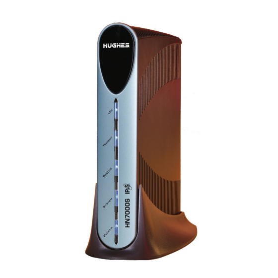
HN7000S overview The HN7000S remote terminal (Figure 2) is a self-hosted terminal with one Ethernet port. An HN7000S terminal connected to a properly aligned antenna assembly can provide satellite Internet or intranet connectivity to a single host or multiple hosts on a local area network (LAN). -
Page 20: Hn7700S Overview
Network Automatic Dial Backup (VADB) feature. VADB is designed for enterprise customers. Serial port These connectors are present on the HN7700S only. (The HN7000S has Phone jack for VADB support 1 LAN port.) LAN 1 Dual Ethernet ports LAN 2... -
Page 21: Vadb
T0156003 Figure 4: HN7700S VADB connection If the satellite link between the HN7700S and the Hughes Network Operations Center (NOC) fails or degrades below a certain threshold, the HN7700S automatically switches to VADB mode. The terminal’s internal modem establishes a connection to Chapter 1 •... -
Page 22: Optional Protection Module
The serial port is programmable for synchronous or asynchronous operation. A single serial device can be connected to the port as shown in Figure 5. A Hughes serial appliance connected to a remote terminal Ethernet port can support multiple serial devices. -
Page 23: Dual Ethernet Ports
Ethernet mode, as shown in Figure 6. Figure 6: Ethernet port LEDs The ports support a wide range of devices, including: • PCs equipped with network interface cards (NICs) • Hughes serial appliance, which can support up to four serial devices • Hubs • Routers •... -
Page 24: Using The Pedestal Base
Use it to mount the remote terminal in a vertical position. The HN7000S consumer terminal is designed only for vertical positioning and must be mounted on the pedestal base as shown in Figure 7. Removing the pedestal base and placing this unit in a horizontal orientation will cause the unit to overheat. - Page 25 WARNING • Do not insert objects through the vents. • Inserting objects through the vents may result in severe personal injury or death due to electric shock. • In addition, inserting objects through the vents may damage the terminal. CAUTION •...
-
Page 26: Power Cycling The Terminal
Power cycling the terminal Some troubleshooting steps require you to restart the remote terminal using the Restart function in the System Control Center (SCC) or to power cycle the remote terminal. Follow the instructions precisely. Power cycling instead of using the Restart function will destroy valuable troubleshooting data. -
Page 27: System Control Center
Internet browsing. It provides access to important system information, configuration parameters, documentation, and help topics. The System Control Center software is embedded in the HN7000S terminal. You access it through your Web browser. Note: The System Control Center’s formal name is the Satellite Terminal HN7000 System Control Center. -
Page 28: Accessing The System Control Center
Accessing the System Open the System Control Center by double-clicking the System Control Center shortcut on your desktop. If this shortcut is not on Control Center your desktop, follow these steps: 1. Open a web browser such as Internet Explorer or Netscape. 2. -
Page 29: Alternate Method For Creating The Shortcut
You should see the System Control Center home page. 3. Drag the icon between (see Figure 9) to Address http the computer desktop. Drag icon to the desktop. Figure 9: Icon for creating a shortcut Alternate method for An alternate method for creating a shortcut to the System Control Center follows: creating the shortcut 1. -
Page 30: Entering The Url In The Create Shortcut Window
3. Type in the field on the Create Shortcut 192.168.0.1 window as shown in Figure 11. Figure 11: Entering the URL in the Create Shortcut window 4. Click Next. 5. Type in the field on the Select a System Control Center Title for the Program window as shown in Figure 12. -
Page 31: System Control Center Home Page
System Control Center The System Control Center home page includes buttons and links to terminal features and important information regarding the home page operation of your terminal. System buttons At the top of the System Control Center page and all information pages are four round labeled buttons, as shown in Figure 13. -
Page 32: Fair Access Policy In Effect
– If the button is orange, as shown in Figure 15, the remote terminal has exceeded the Fair Access Policy (FAP) threshold (only applicable for HN7000S). Each HughesNet service plan has an established download threshold. Subscribers who exceed that threshold will experience reduced download speeds for approximately 24 hours. -
Page 33: Links
serial number, and the site ID. For more information, see System Info page on page 24. Links The System Control Center home page has four groups of links: • System Status • Diagnostic Utilities • Help • myHughesNet (visible only to users in the United States who purchased their terminal through a retail channel) System Status The following links provide access to system status information: •... -
Page 34: Myhughesnet
Restart HN7000S Restart HN7700S) enables you to restart the terminal. myHughesNet If you purchased your remote terminal from a Hughes retail channel in the United States, you can access myHughesNet (hughesnet.myway.com), a Web portal that contains a variety of interactive tools. -
Page 35: System Status Page
System status page The System Status page (Figure 17) displays important information about the terminal’s operational status. Figure 17: System Status page • – Displays the receive signal strength. A Signal Strength value of 30 or less indicates an appropriate signal is not being received. - Page 36 have recently browsed HTTP-based Web sites. Web Acceleration may be inactive if you are browsing on a secure HTTP site (https). Secure HTTP does not support Web Acceleration, which will resume operation once you return to an HTTP site. The status button will be yellow if Web Acceleration is being bypassed.
-
Page 37: Reception Info Page
Clicking the blue status message displays corresponding help information. • – Reports the number of data messages Frames Received received by the HN7000S over the satellite link. • Frames with Errors – Reports the percentage of received frames found to be corrupted. Any number greater than zero indicates a problem except when adverse weather conditions are present. -
Page 38: Transmission Info Page
Number of Packets submitted for transmission total number of data packets transmitted. System Info page The System Info page shown in Figure 20 has four sections: HN7000S Info, Satellite, Transmit Radio Info, and Software Chapter 2 • System Control Center 1037073-0001 Revision E... -
Page 39: System Information Page
Information page may not be accessible if a problem occurs. If you call Your service provider for assistance, you will need the Site ID, serial number, and software release. • HN7000S Info section – Identifies your site. – Site ID –... - Page 40 (NAT) – Typically used to Network Address Translation allow multiple computers to share a single address on the Internet. It also allows pre-configured remote networks to be integrated easily with the Hughes network. – (DHCP) – If enabled, Dynamic Host Configuration Protocol this simplifies the network configuration of the computers.
-
Page 41: Troubleshooting Page
– – If enabled, allows you to specify packet filtering Firewall rules. This feature is locally enabled. – – If enabled, speeds web browsing. This Turbo Page feature is enabled at the NOC according to the service offering. Troubleshooting page The System Control Center’s Problem Troubleshooting page, shown in Figure 21, provides access to troubleshooting procedures for some common user problems. -
Page 42: Detailed Problem Statistics Page
Once you have selected the appropriate information, the system attempts to diagnose the problem and offers possible solution advice as shown in Figure 22. Figure 22: Problem diagnosis help Detailed Problem The Detailed Problem Statistics page allows you to view statistics for a selected problem for a specific hourly time frame. -
Page 43: Connectivity Test Page
Figure 23: Detail Problem Statistics selection Figure 24: Statistics report sample Connectivity Test page The Connectivity Test page has a link that can be used to test the HN7000S’ connectivity to the NOC. Chapter 2 • System Control Center 1037073-0001 Revision E... -
Page 44: Port Forwarding Configuration Page
Forwarding has been enabled and made visible on your terminal by the NOC. Note: This feature is not available for the HN7000S terminal. This page allows you to define rules for allowing TCP and User Datagram Protocol (UDP) traffic on the Internet to access servers on your network. -
Page 45: Defining Port Forwarding Rules
Defining port forwarding Follow these steps to use the Port Forwarding Configuration page to define port forwarding rules: rules 1. Open a Web browser on a computer connected to the HN7700S. You may also use a computer on the LAN if the HN7700S is connected to an Ethernet device, such as a hub or router. -
Page 46: Browsing Optimization Utility
Follow these steps to download and install the utility: 1. Open a Web browser on a computer connected to the HN7000S. 2. Navigate to the System Control Center home page, as instructed in Accessing the System Control Center on page 14. -
Page 47: Hughesnet Tools
Hughes Customer Care. Note: HughesNet Tools and the HughesNet Software Activation CD are available for the HN7000S only. As of the date of this User Guide, these features are not available for the HN7700S. The Activation Software CD is included in the shipping container when you receive your HN7000S terminal. -
Page 48: Installing The Hughesnet Tools Using The Cd
1. Launch Internet Explorer, and go to customercare.myhughesnet.com by downloading software 2. Under HughesNet Tools and Security, click from the Hughes site Introduction to HughesNet Tools 3.Click For information on downloading from the Internet, Click Here 4. Follow the instructions in the topic How to Download... -
Page 49: Hughesnet Tools Home Page
• Double-click the HughesNet Tools system tray icon (Figure 29). HughesNet icon, enlarged Windows system tray Figure 29: HughesNet Tools system tray icon The HughesNet Tools home page opens, as shown in Figure 30. HughesNet Tools home The HughesNet Tools home page includes links to specific tools as illustrated in Figure 30. -
Page 50: I Have A Technical Problem
I Have a Technical Problem I have a Technical Problem is the first group of links: • I am Unable to Browse the Internet – This tool tests your Internet connection. If the test fails, the tool suggests options for solving the problem. Support Library The Support Library area includes one link: •... -
Page 51: Remote Terminal Leds
Chapter 4 Remote terminal LEDs The LEDs provide information about the remote terminal’s operating status. If the LEDs are not functioning as described in this chapter, refer to Using the terminal LEDs to troubleshoot on page 56. This chapter describes the following LEDs: •... -
Page 52: Startup Led Test
When the terminal is powered on and transmitting or receiving data, the LEDs should appear as follows: • LAN, Transmit (HN7000S) or Transmit/WAN (HN7700S), and Receive (HN7000S) or Receive/PPP-IP (HN7700S) LEDs – Mostly on, but blinking intermittently as the terminal receives and transmits data. -
Page 53: Fatal Error Indication
If the LEDs do not function properly as described in this chapter, check the sticker on the power supply and verify that you have the correct power supply. For an AC/DC power supply, the Hughes part number on the power supply should be one of the following: 1031105-0001 1500089-0001 1500081-0001 (HN7000S only;... -
Page 54: Ethernet Port Leds
Ethernet port LEDs The HN7000S remote terminal has one Ethernet port. The HN7700S has two Ethernet ports. The Ethernet port supports a wide range of devices, including: • PC equipped with a network interface card (NIC) • Hub • Router •... -
Page 55: Troubleshooting
Chapter 5 Troubleshooting This chapter provides general troubleshooting procedures. The following situations and topics are discussed: • Problem troubleshooting information • Cannot access the System Control Center on page 55 • Using the terminal LEDs to troubleshoot on page 56 •... -
Page 56: Problem Troubleshooting Information
Problem If you experience trouble with your terminal, the Problem Troubleshooting link on the System Control Center page may troubleshooting have the information you need. You should try this link before information calling your service provider. Problem 1. On the System Control Center page, click Troubleshooting as shown in Figure 34. - Page 57 Figure 35: Select problem list 3. Select the appropriate problem. 4. Click the down arrow for the time box to display a list of time intervals. Select the appropriate timeas shown in Figure 36. Figure 36: Select time list Chapter 5 • Troubleshooting 1037073-0001 Revision E...
-
Page 58: Can Access The System Control Center But Not The Internet
5. Click Diagnose. The results page displays giving you information on your problem as shown in Figure 37. Figure 37: Diagnose/results screen Can access the System If you can access the System Control Center but you cannot access the Internet, you may be able to resolve the problem by Control Center but not the performing the following troubleshooting procedures: Internet... -
Page 59: Confirming That The Terminal Is Commissioned
terminal is commissioned on page 45. Also, try the troubleshooting procedures more than once before contacting your service provider. If you cannot access the System Control Center by double-clicking the System Control Center shortcut or typing in the browser’s address www.systemcontrolcenter.com bar, try typing instead, then press E... -
Page 60: Confirming Receive Signal
appears, the terminal is not Not Commissioned commissioned. Contact your service provider. Confirming receive signal The terminal will not function if satellite signals are not received properly. 1. At the System Control Center, click the Reception Info link. The Reception Information page appears. See Figure 39. Figure 39: Confirming receive signal 2. -
Page 61: Confirming Transmit Signal
Confirming transmit signal The terminal will not function if satellite signals are not transmitted properly. 1. At the System Control Center, click the Transmission Info link. The Transmission Information page appears. See Figure 40. Figure 40: Confirming transmit signal 2. In the field, check the transmit (Tx) code. -
Page 62: Confirming That Tcp Acceleration Is Operational
Confirming that TCP TCP Acceleration is a proprietary protocol provided by Hughes. It optimizes performance for TCP and Internet Protocol acceleration is operational (IP)-based applications, including faster downloads over satellite. 1. At the System Control Center, click the System Status link. -
Page 63: Confirming That Web Acceleration Is Operational
Internet, contact your service provider for assistance. Confirming that Web Web Acceleration is a proprietary protocol provided by Hughes. It optimizes Web browsing performance. acceleration is operational 1. At the System Control Center, click the System Status link. -
Page 64: Confirming Noc Connectivity
Confirming NOC Use the Connectivity Test link to check connectivity to the Hughes Network Operations Center (NOC). connectivity Note: You may want to open a second browser window to access the Help page while conducting the Connectivity Test. Chapter 5 • Troubleshooting... -
Page 65: Accessing The Connectivity Test
1. Click Connectivity Test on the left side of the System Control Center. The Connectivity Test page shown in Figure 42 appears. Figure 42: Accessing the Connectivity Test page 2. Click Start Test. A message appears informing you if the test was successful. - Page 66 g. At the prompt, type followed by a space and then ping type the router address. For example, if the router address is 100.100.100.100, type ping 100.100.100.100 h. Press E NTER If the ping is successful, the ping results show that all sent packets were received, as in Figure 43.
-
Page 67: Confirming Internet Connectivity
If you lose Internet connectivity, complete these troubleshooting steps: 1. Open a command prompt on a computer connected to the terminal. 2. Ping the Hughes web server: a. Type ping www.HughesNet.com b. Press E NTER Chapter 5 • Troubleshooting... -
Page 68: Checking Dns Settings
If a firewall is used, make sure none of its settings are blocking access to the Internet or to the Hughes servers. Make sure you are using the latest version of any anti-virus and/or firewall software. -
Page 69: Cannot Access The System Control Center
Cannot access the If you cannot access the System Control Center, refer to the troubleshooting procedures for the appropriate hardware System Control Center configuration: • Computer is connected directly to the terminal on page 55 • Terminal is connected to an Ethernet device on page 55 Computer is connected Follow the steps below if your computer is connected directly to the terminal. -
Page 70: Using The Terminal Leds To Troubleshoot
Using the terminal LEDs This section explains how to use LED appearance to troubleshoot. Refer to Figure 45 for power and cable connections to troubleshoot when completing a troubleshooting procedure. Computer Ethernet cable AC power cord DC power Power cord supply Receive Transmit... -
Page 71: Fatal Error Indication
Note: The remote terminal may operate correctly when first installed even if the transmit and receive cable connectors are not adequately tightened. However, problems could develop later. Therefore, correct operation of the terminal is not an indication that the cables are adequately tightened. Fatal error indication If after power-up or a reset the Power LED is off and one or more of the other LEDs is flashing, the terminal could have a fatal error... -
Page 72: Checking The Power Led
3. If the LEDs are still off, determine if the power source is faulty: a. Unplug the terminal AC power cord from the power outlet. If the terminal AC power cord is connected to a power strip or surge protector, unplug the power strip or surge protector from the power outlet. - Page 73 If the My Computer icon is not available, click → → → Start Settings Control Panel Administrative → → Tools Computer Management System → Tools Device Manager 4. If the LAN LED is still off after fixing any NIC problems, check the terminal’s back panel LEDs.
-
Page 74: Problems When Other Devices Are Connected To The Terminal
If the LAN LED is on, but was off before you made this direct connection, there is probably a problem with your network device or the connections to it. Check those connections. If the LAN LED is still off, contact the manufacturer of the network device for assistance. -
Page 75: System Led Is Off
2. Restart the terminal: a. Go to the System Control Center home page. b. In the Help section, click Restart HN7000S Restart HN7700S). 3. If this does not correct the problem, power cycle the terminal:... -
Page 76: Troubleshooting Other Problems
2. If the LED does not turn on after 15 minutes, power cycle the terminal: CAUTION Do not power cycle the terminal by unplugging the power cord from the back of the terminal. This could shock you and/or damage the terminal. a. -
Page 77: Slow Transmission Speed Or Intermittent Operation
Slow transmission speed or If you notice that the terminal’s transmission speed is slow or that operation is intermittent, make sure the transmit and receive cable intermittent operation connectors are finger tight. (See the Caution statement and note concerning cable connector tightness following Figure 45 on page 56.) Troubleshooting VADB If you suspect the HN7700S is not working properly in VADB... - Page 78 Chapter 5 • Troubleshooting 1037073-0001 Revision E...
-
Page 79: Typical Operating System Settings
Appendix A Typical Operating System Settings This appendix explains how to configure Windows and Macintosh operating system settings so that your computer can communicate with the terminal. The following topics are discussed: • Determining if DHCP is enabled on the remote terminal on page 65 •... -
Page 80: Configuring Windows For A Static Ip Address
Note: Home networking equipment is required but not included. For network setup, support and configuration, contact your network hardware manufacturer and/or operating system software developer (Hughes is not responsible for home network management or troubleshooting). Simultaneous use of high bandwidth applications by multiple users may result in degradation of speed. -
Page 81: Windows Vista
Control Center. You would have also written this on the Quick Start Guide at the end of registration. Note: If your terminal will be connected to a router, you must configure the router with the static IP address. Refer to the instructions included with your router to configure it. -
Page 82: Local Area Connections
3. Right-click the Local Area Connection icon that represents the Network adapter that connects the computer to the terminal and select Properties. See Figure 47. Note: If the Local Area Connection icon appears with a red X then check your connections. The red X must not be present in order to successfully configure your operating system’s settings. -
Page 83: Tcp/Ip Properties
5. Select Internet Protocol (TCP/IP) and select Properties being careful not to uncheck the check box. See Figure 48. Figure 48: TCP/IP Properties 6. In the General tab, select Use the following IP . Enter an appropriate IP address from the range of address available IP addresses and the appropriate Subnet Mask for your network in the fields provided. -
Page 84: Windows Xp
the terminal for the Default Gateway. Enter 66.82.4.8 the Preferred DNS server field. See Figure 49. Figure 49: Entering the preferred DNS server address 7. Select OK to close the open dialog boxes and finish the configuration. 8. Restart the computer even if Windows does not prompt you to do so. -
Page 85: Network And Dialup Connections
Figure 50: Network and Dialup Connections 2. A list of Network adapters appears. A Local Area Connection icon must be listed under LAN or High-Speed Internet. If not, the network is not installed correctly. 3. Right-click the Local Area Connection icon that represents the Network adapter that connects the computer to the terminal and select Properties. -
Page 86: Tcp/Ip Properties
Figure 51: Local Area Connections 4. Ensure the Client for Microsoft Networks and Internet Protocol (TCP/IP) are installed and checked. If NetBEUI is installed, uninstall it. 5. Select Internet Protocol (TCP/IP) and select Properties being careful not to uncheck the check box. See Figure 52. Figure 52: TCP/IP Properties Appendix A •... -
Page 87: Entering The Preferred Dns Server Address
6. In the General tab, select Use the following IP . Enter an appropriate IP address from the range of address available IP addresses and the appropriate Subnet Mask for your network in the fields provided. Enter the IP address of the terminal for the Default Gateway. -
Page 88: Windows 2000
Windows 2000 1. Select Start→ Settings→ Control Panel 2. Select the icon. See Network and Dialup Connections Figure 54. Figure 54: Network and Dialup Connections 3. Right-click the Local Area Connection that connects to the terminal and select Properties . See Figure 55. Figure 55: Local Area Connections Appendix A •... -
Page 89: Local Area Connection Properties
4. Ensure the Client for Microsoft Networks and Internet Protocol (TCP/IP) are installed and checked. If NetBEUI is installed, uninstall it. 5. Select Internet Protocol (TCP/IP) being careful not to uncheck it, and then select Properties. See Figure 56. Figure 56: Local Area Connection Properties 6. -
Page 90: Tcp/Ip Properties
9. Enter for the Preferred DNS server field. See 66.82.4.8 Figure 57. Figure 57: TCP/IP Properties 10. Select OK to save and close Internet Protocol (TCP/IP) Properties. 11. Select Close again to save and close Local Area Connection Properties. 12. Reboot the PC if necessary. Appendix A •... -
Page 91: Windows 98Se Or Me
Windows 98SE or Me 1. Select Start→ Settings→ Control Panel 2. Select . The configuration dialog box opens Network Network to the tab. See Figure 58. Configuration Figure 58: Network dialog with Configuration tab 3. Select the TCP/IP protocol bound to the NIC connected to the remote terminal and select Properties. -
Page 92: Tcp/Ip Properties
Figure 59: TCP/IP Properties 4. Select Specify an IP Address. Enter an appropriate IP address from the range of available IP addresses. Refer to page 66 for more information on how to view available IP addresses. 5. Enter the appropriate subnet mask in the Subnet Mask field. -
Page 93: Entering The Terminal's Ip Address
6. Select the tab. Enter the terminal IP Address in the Gateway field. See Figure 60. New Gateway Figure 60: Entering the terminal’s IP address 7. Select Add. 8. Select the DNS Configuration tab, and verify the following settings: a. Make sure Enable DNS is selected. -
Page 94: Configuring Windows To Support A Dhcp-Enabled Terminal
Configuring Windows to This section explains how to configure Windows operating systems to support a DHCP-enabled terminal. support a DHCP-enabled terminal → → Windows Vista 1. From the Windows desktop, select Start Settings Network Connections A list of network adapters appears as shown in Figure 61. The Local Area Connection-NIC Card must appear under the LAN or High-Speed Internet heading. -
Page 95: Local Area Connection Properties - Windows Vista
Properties. The Local Area Connection-NIC Card Properties dialog appears as shown in Figure 62. Note: Depending on your security settings, a popup User Account Control message may appear, requesting that you confirm the action before proceeding. Click Continue to proceed. Figure 62: Local Area Connection Properties - Windows Vista 3. -
Page 96: Windows Xp
5. Click Properties. The Internet Protocol Properties dialog appears as shown in Figure 63. Figure 63: Internet Protocol Properties - Windows Vista 6. Ensure that both the Obtain an IP address automatically options are Obtain DNS server address automatically selected. If not, select them. 7. -
Page 97: Network Connections - Windows Xp
High-Speed Internet heading. If it does not, the network is not installed correctly. Figure 64: Network Connections - Windows XP 2. Right-click the Local Area Connection icon that represents the Network adapter connecting the computer to the Satellite Gateway, and select Properties. Note: If a red X appears next to the Local Area Connection icon, check your connections. -
Page 98: Local Area Connection Properties - Windows Xp
3. Ensure that Client for Microsoft Networks Internet Protocol (TCP/IP) are installed and checked as shown in Figure 65. If NetBEUI is installed, uninstall it. Figure 65: Local Area Connection Properties - Windows XP 4. Highlight Internet Protocol (TCP/IP) . Be careful not to uncheck the check box. -
Page 99: Windows 2000
6. Ensure that both the Obtain an IP address automatically options are Obtain DNS server address automatically selected. If not, select them. 7. Click OK to close the dialog boxes and finish the configuration. 8. Restart the computer even if Windows does not require you to do so. -
Page 100: Local Area Connection Properties - Windows 2000
the popup menus. The Local Area Connections Properties window appears as shown in Figure 68. Figure 68: Local Area Connection Properties - Windows 2000 3. Ensure that Client for Microsoft Networks Internet Protocol (TCP/IP) are installed and checked. If NetBEUI is installed, uninstall it. -
Page 101: Internet Protocol Properties - Windows 2000
5. Click . The window Properties Internet Protocol Properties appears as shown in Figure 69. Figure 69: Internet Protocol Properties - Windows 2000 6. Ensure that both Obtain an IP Address Automatically are selected. If Obtain DNS Server Address Automatically not, select them. -
Page 102: Windows 98Se And Me
→ → Windows 98SE and Me 1. From the Windows desktop, select Start Settings , then double-click Network. See Figure 70. Control Panel Figure 70: Control Panel - Windows 98SE and Me Note: On computers running on Windows Me, choose View All Control Panel Options to see the Network icon. -
Page 103: Tcp/Ip Properties - Windows 98Se And Me
Figure 71: Network window - Windows 98SE and Me 2. Select the TCP/IP entry associated with the Network Interface Card (NIC), then click Properties. The TCP/IP Properties window appears as shown in Figure 72. Figure 72: TCP/IP Properties - Windows 98SE and Me Appendix A •... -
Page 104: Configuring A Macintosh For A Static Ip Address
3. On the tab, select the Obtain an IP address IP Address automatically radio button. 4. Select the Gateway tab. Remove any installed gateways by selecting them and clicking Remove. See Figure 73. Figure 73: Gateway tab - Windows 98SE and Me 5. -
Page 105: Mac Network Screen
2. Select the icon, which is circled in Figure 74. The Network Network screen shown in Figure 75 appears. Figure 74: Mac Systems Preferences menu Figure 75: Mac Network screen 3. Make sure the TCP/IP tab is selected. Appendix A • Typical Operating System Settings 1037073-0001 Revision E... -
Page 106: Configuring A Macintosh To Support A Dhcp-Enabled Terminal
4. Select the drop-down list. See Figure 76. Configure Figure 76: Select Manually from the Configure drop-down list 5. Select Manually 6. Type the appropriate IP address from the range of available IP addresses in the IP Address field. Do not use the numbers in the examples, which are for illustrative purposes only. -
Page 107: Mac Network Screen
2. Select the icon, which is circled in Figure 77. The Network Network screen shown in Figure 78 appears. Figure 77: Mac System Preferences menu Figure 78: Mac Network screen 3. Make sure the TCP/IP tab is selected. Appendix A • Typical Operating System Settings 1037073-0001 Revision E... -
Page 108: Select Dhcp From The Configure Drop-Down Menu
4. Select the drop-down list. See Figure 79. Configure Figure 79: Select DHCP from the Configure drop-down menu 5. Select . Notice the field grays out. Using DHCP IP Address 6. Select the Apply Now button. The Mac is now configured. Appendix A •... -
Page 109: Home Networking
Appendix B Home Networking This appendix applies to the HN7000S terminal only. The HN7700S terminal is designed for enterprise applications. A terminal connected to a properly aligned antenna assembly can provide satellite connectivity for multiple computers on a wireless or wired (Ethernet) LAN. After the terminal and network are installed, every computer on the network can access the Internet through the satellite signal. -
Page 110: Basic Wireless Considerations
Basic wireless Wireless networks are easy to install because you do not have to run any cables. Instead, a wireless base station is connected to the considerations terminal Ethernet port. Wireless NICs are installed in each computer you want on the network. These components are available at most computer supply stores and outlets. -
Page 111: Basic Ethernet Considerations
Basic Ethernet Ethernet hubs, cables, and NICs can be purchased at most computer supply stores or outlets. They are relatively inexpensive considerations and easy to install. The Ethernet interface must support auto-negotiate, a feature that enables compatibility and inter-operability among Ethernet devices. Select an Ethernet hub based on how many computers or other devices are connected to the network, and how fast you need the data connection to be. - Page 112 cable in case you have to repair it, which usually involves cutting away a damaged section. Prepared Ethernet cable, cable that already has RJ-45 jacks installed at the ends, is usually available in lengths of no more than 50 ft. If the cable length exceeds 50 ft, use a kit to install the RG-45 jacks at both ends of the cable.
-
Page 113: Conformance With Standards
Appendix C Conformance with standards and directives The HN7000S and HN7700S remote terminals have been certified to conform to the standards shown in Table 2. Additional information follows the table. Table 2: HN7000S and HN7700S standards compliance Category Standard HN7000S... -
Page 114: Safety - Operating Conditions For Canada
In addition to the warnings and safety guidelines listed in this document, the following operating conditions apply to the conditions for Canada HN7000S and HN7700S remote terminals used in Canada: The Canadian Department of Communications label identifies certified equipment. This certification means that the equipment meets certain telecommunications network protective operational and safety requirements. -
Page 115: Electromagnetic Compatibility (Emi)
FCC Part 15 This section applies to the HN7000S and HN7700S remote terminals. Standards to which Conformity is declared: FCC Part 15 This device complies with part 15 of the FCC Rules. -
Page 116: Canada Class B Warning
(IPoS) and FCC Part 68. standards IPoS The Hughes HN System is compliant with the IP over Satellite standard (IPoS) ratified by the Telecommunications Industry Association (TIA-1008), first published in October 2003 and issued as Revision A in May 2006. -
Page 117: Ringer Equivalence Number (Ren)
Discontinuance of service This section applies to the HN7700S remote terminal only. If the Two-Way Hughes System causes harm to the telephone network, the Telephone Company will notify you in advance that temporary discontinuance of service may be required. But if advance notice isn’t practical, the Telephone Company will notify... -
Page 118: Repairs In The United States
Telephone Company may request that you disconnect the equipment until the problem is resolved. Hughes must make any necessary repairs to the modem portion of this equipment in order to maintain valid FCC registration. Do not attempt to repair or service your remote terminal. Instead, return it to Hughes. - Page 119 Before installing this equipment, users should make sure they are permitted to connect to the facilities of the local Telecommunications Company. The equipment must also be installed using an acceptable method of connection. In some cases, the company's inside wiring associated with a single line individual service may be extended by means of a certified connector assembly (telephone extension cord).
- Page 120 Appendix C • Conformance with standards and directives 1037073-0001 Revision E...
-
Page 121: Acronyms And Abbreviations
Acronyms and abbreviations LED – Light-emitting diode ASC – Authorized Service Center ATM – Automated teller machine NAT – Network address translation AWG – American Wire Gauge NIC – Network interface card NOC – Network Operations Center CD-ROM – Compact disk - read only memory PC –... - Page 122 VADB – Virtual private network dial backup VAR – Value added reseller VPN – Virtual private network • Acronyms and abbreviations 1037073-0001 Revision E...
-
Page 123: Index
HN7700S 19, 29, 50 Connectivity test description Contact information Ethernet ports Hughes Customer Care Hughes serial appliances HughesNet Activation Software CD HughesNet Customer Care HughesNet Tools Detailed Problem Statistics page home page DHCP setting installing DNS settings... - Page 124 System Control Center Ports LEDs Power blinking, defined troubleshooting Ethernet port Power supply, checking for correct type Ethernet ports Powering down the terminal flashing, defined Preventive maintenance indications (table) normal operation overview Reception Info page startup test Remote terminal, how it works using to troubleshoot problems Repairs Local Area Network.
- Page 125 TCP acceleration Telecommunications standards Transmission Info page Troubleshooting cannot access Internet cannot access System Control Center fatal error indication firewalls hot cable connector Internet connectivity NOC connectivity power slow speed System Control Center using LEDs for troubleshooting viruses with other devices connected to terminal VADB connections description...
- Page 126 • Index 1037073-0001 Revision E...
Need help?
Do you have a question about the HN7000S and is the answer not in the manual?
Questions and answers