Table of Contents
Advertisement
Advertisement
Table of Contents

Related Manuals for PaloAlto Networks PA-200


Summary of Contents for PaloAlto Networks PA-200
- Page 1 PA-200 Firewall Hardware Reference Guide...
-
Page 2: About This Guide
About this Guide This guide describes the PA-200 firewall hardware, provides instructions on installing the hardware, describes how to perform maintenance procedures, and provides product specifications. This guide is intended for system administrators responsible for installing and maintaining the PA-200 firewall. -
Page 5: Table Of Contents
May 20, 2015 - Palo Alto Networks COMPANY CONFIDENTIAL Table of Contents Chapter 1 Overview ..........Front Panel . - Page 6 4 • Table of Contents Palo Alto Networks...
-
Page 7: Chapter 1 Overview
May 20, 2015 - Palo Alto Networks COMPANY CONFIDENTIAL Chapter 1 Overview This chapter describes the front and back panels of the PA-200 firewall. For more information, refer to the following topics: • “Front Panel” in the next section •... -
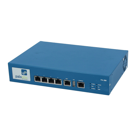
Page 8: Front Panel
Front Panel Front Panel Figure 1 shows the front panel of the PA-200 firewall. Ethernet ports LEDs Management Console port port port Figure 1. Front Panel Table 1 describes the front panel features. Table 1. Front Panel Features Item Description Ethernet ports 4 RJ-45 10/100/1000 ports for network traffic. -
Page 9: Back Panel
Back Panel Back Panel Figure 2 shows the back panel of the PA-200 and Table 2 describes the back panel features. DC power Figure 2. Back Panel Table 2. Back Panel Features Item Description Power inlet DC power inlet for powering the device. - Page 10 Back Panel 8 • Overview Palo Alto Networks...
-
Page 11: Installing The Hardware
May 20, 2015 - Palo Alto Networks COMPANY CONFIDENTIAL Chapter 2 Installing the Hardware This chapter describes how to install the PA-200 firewall. For more information, refer to the following topics: • “Tamper Proof Statement” on page 9 •... -
Page 12: Connecting Cables To The Device
Note: The PA-200 firewall uses a combination of passive and active cooling and needs proper airflow on all surfaces to ensure proper operation. Do not install the PA-200 firewall in a small, confined space such as a closed shelf or drawer, as this could lead to insufficient cooling of the device. -
Page 13: Maintaining The Hardware
May 20, 2015 - Palo Alto Networks COMPANY CONFIDENTIAL Chapter 3 Maintaining the Hardware This chapter provides maintenance information for the PA-200 hardware. For more information, refer to the following topics: • “Cautions and Warnings” in the next section •... -
Page 14: Interpreting The Device Leds
Removal of equipment top cover is to be performed only by trained service person(s). Interpreting the Device LEDs Figure 4 shows the LEDs on the front panel of the PA-200 firewall. Figure 4. Front Panel LEDs Table 3 describes the LED functions and states. -
Page 15: Interpreting The Port Leds
Interpreting the Port LEDs Interpreting the Port LEDs Each Ethernet port on the PA-200 firewall has two LEDs. Table 4 describes the LEDs. Table 4. Port LEDs Description Left Shows green if there is a network link. Right Blinks if there is network activity. - Page 16 Interpreting the Port LEDs 14 • Maintaining the Hardware Palo Alto Networks...
-
Page 17: Chapter 4 Specifications
May 20, 2015 - Palo Alto Networks COMPANY CONFIDENTIAL Chapter 4 Specifications This chapter provides specifications for the PA-200 firewall. For more information, refer to the following topics: • “Physical Specifications” in the next section • “Interface Specifications” on page 14 •... -
Page 18: Interface Specifications
• Parity: none • Stop bits: 1 • Flow control: none USB port One USB port for future use. Electrical Specifications Table 7 lists the electrical specifications for the PA-200 firewall. Table 7. Electrical Specifications Specification Description Input frequency 50-60 Hz... -
Page 19: Compliance Statements
May 20, 2015 - Palo Alto Networks COMPANY CONFIDENTIAL Chapter 5 Compliance Statements European Union (EU) Electromagnetic Compatibility Directive This device is herewith confirmed to comply with the requirements set out in the Council Directive on the Approximation of the Laws of the Member States relating to Electromagnetic Compatibility Directive (2004/108/EC). - Page 20 Federal Communications Commission (FCC) Statement: For a Class B digital device or peripheral NOTE: This equipment has been tested and found to comply with the limits for a Class B digital device, pursuant to Part 15 of the FCC Rules. These limits are designed to provide reasonable protection against harmful interference in a residential installation.
Need help?
Do you have a question about the PA-200 and is the answer not in the manual?
Questions and answers