PaloAlto Networks PA-220R Quick Start Manual
Hide thumbs
Also See for PA-220R:
- Quick start manual (2 pages) ,
- Hardware reference manual (42 pages) ,
- Hardware reference manual (40 pages)
Table of Contents
Advertisement
Quick Links
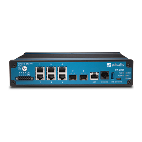
PA-220R
1
Before You Begin
Use this guide to install and begin setting up your Palo Alto Networks
Next-Gen Firewall Hardware Reference at
https://docs.paloaltonetworks.com/hardware
and more detailed procedures for installing your firewall.
◼
Verify that the installation site has a DC power source.
◼
Unpack the equipment and verify that you received the following items:
Qty
Description
1
PA-220R next-generation firewall.
1
Standard Type-A USB to micro USB console cable.
1
DB-9 female to RJ-45 male console cable.
1
Shielded RJ-45 CAT6 Ethernet cable for management (MGT) port access.
1
DC terminal block.
4
Rubber pads for a desktop installation.
1
DIN bracket for a DIN rail installation.
1
End User License Agreement (EULA).
1
China Restriction of Hazardous Substances (RoHS) declaration.
2
Install the Firewall
There are four ways to install the PA-220R firewall:
◼
On a flat surface
◼
On a DIN rail
◼
On a wall
◼
In a 19-inch equipment rack
The PA-220R firewall ships with rubber pads (to install the firewall on a flat surface) and a DIN rail bracket (to install the firewall on a DIN
rail). The wall-mount kit and 19-inch equipment-rack kit are optional and purchased separately—refer to the PA-220R Next-Gen Firewall
Hardware Reference for the wall-mount and rack-kit installation procedures.
Install on a Flat Surface
Attach the rubber pads to the recessed circles on the bottom of the firewall (Figure 1) and place the firewall securely on a stable
flat surface (right-side up).
docs.paloaltonetworks.com
PA-220R next-generation firewall. Refer to the PA-220R
®
for safety information, specifications,
Figure 1
Install on a DIN Rail
You can attach the DIN bracket to either the back or to the bottom surface of the firewall. Choose the option that best fits the
installation site.
1
Attach a 35mm DIN rail (not included) to the wall where you will install the firewall.
2
Attach the DIN bracket to the back (Figure 2) or bottom surface (Figure 4)of the firewall (use the DIN bracket captive screws). Ensure that
the spring-loaded clips on the DIN bracket are oriented so that they will grasp the bottom of the DIN rail.
3
Engage the bottom of the DIN bracket (with spring-loaded clips) with the bottom part of the DIN rail. Push the firewall and bracket upward
to fully compress the spring-loaded clips against the rail and then pivot the firewall toward the wall so that the top clips on the bracket will
grasp the top of the rail as you carefully lower the firewall to decompress the clips and secure the firewall on the DIN rail (Figure 3 or Figure
5).
Figure 2
DIN Bracket
Figure 4
Page 1 of 2
Quick Start Guide
Cap ve Screw
DIN Bracket
Spring-loaded
DIN Bracket Clips
Cap ve Screw
Figure 3
Cap ve Screw
Spring-loaded
DIN Bracket Clips
Cap ve Screw
Figure 5
Wall
DIN Rail
Spring-loaded
DIN Bracket Clips
Wall
DIN Rail
Spring-loaded
DIN Bracket Clips
Advertisement
Table of Contents

Related Manuals for PaloAlto Networks PA-220R


Summary of Contents for PaloAlto Networks PA-220R
- Page 1 Figure 2 The PA-220R firewall ships with rubber pads (to install the firewall on a flat surface) and a DIN rail bracket (to install the firewall on a DIN rail). The wall-mount kit and 19-inch equipment-rack kit are optional and purchased separately—refer to the PA-220R Next-Gen Firewall Hardware Reference for the wall-mount and rack-kit installation procedures.
- Page 2 Power On the Firewall Connect to the Management Interface The PA-220R firewall requires a 12-48VDC 1.4A power source. You can connect a second DC power source for redundancy. Connect with Standard Firewall Due to the various cable lengths required for a given installation site, DC power and ground cables are not included.
Need help?
Do you have a question about the PA-220R and is the answer not in the manual?
Questions and answers