PaloAlto Networks PA-7000 Series Hardware Reference Manual
Networks enterprise firewall
Hide thumbs
Also See for PA-7000 Series:
- Hardware reference manual (220 pages) ,
- Hardware reference manual (206 pages) ,
- Hardware reference manual (50 pages)
Table of Contents
Advertisement
Quick Links
Advertisement
Chapters
Table of Contents

Related Manuals for PaloAlto Networks PA-7000 Series


Summary of Contents for PaloAlto Networks PA-7000 Series
- Page 1 Palo Alto Networks PA-7000 Series Hardware Reference Guide...
-
Page 2: About This Guide
This guide is intended for system administrators responsible for installing and maintaining a PA-7000 Series firewall. All PA-7000 Series firewalls run PAN-OS®, a purpose-built operating system with extensive security and networking functionality. For additional information, refer to the following resources: For information on the additional capabilities and for instructions on configuring the features on the firewall, refer ... -
Page 3: Table Of Contents
Chapter 1 PA-7000 Series Firewall Overview ......PA-7050 Front and Back Panel Descriptions ...... - Page 4 Interpret the PA-7000 Series Firewall Power Supply LEDs ....93 Replace a PA-7000 Series AC Power Supply ......95 Replace a PA-7000 Series DC Power Supply .
-
Page 5: Pa-7000 Series Firewall Overview
(HA) control port (HA1), as well as two dedicated 80Gb QSFP HA ports for HA2 (data link) and HA3 (packet forwarding) functions. These dedicated HA ports enable PA-7000 Series firewalls to function with full hardware redundancy in either an active/passive or active/active configuration. Additionally, to improve logging performance, the firewalls use a dedicated log card to handle all log processing tasks. -
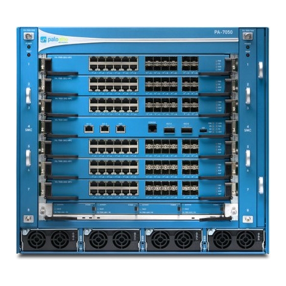
Page 6: Pa-7050 Front Panel (Ac)
POWER FAULT FAULT PA-7000-BLANK PA-7000-BLANK PA-7000-BLANK PA-7050-SMC CONSOLE HSCI-A HSCI-B HA1-A HA1-B PA-7000-BLANK PA-7000-BLANK PA-7000-20G-NPC ACTIVITY POWER ACTIVITY POWER ACTIVITY POWER ACTIVITY POWER FAULT FAULT FAULT FAULT PA-7000-AMC-1TB PA-7000-AMC-1TB PA-7000-AMC-1TB PA-7000-AMC-1TB 6 • PA-7000 Series Firewall Overview Palo Alto Networks... - Page 7 AMC and drives are ordered and installed as one unit. IMPORTANT: The LPC is required and must be installed in slot 8 for chassis operation. For more information, see “Log Processing Card (LPC)” on page 30. Palo Alto Networks PA-7000 Series Firewall Overview • 7...
-
Page 8: Pa-7050 Back Panel (Ac)
ESD ports. PA-7050 Back Panel (AC) Figure 2 shows the back panel of the PA-7050 firewall and Table 2 describes the back panel features. Figure 2. PA-7050 Back Panel (AC) 8 • PA-7000 Series Firewall Overview Palo Alto Networks... - Page 9 Power Entry Module Provides switches to power on or off the AC power supplies. Each switch has a circuit breaker that will trip if the load reaches 25-amps. (PEM) AC power switches Palo Alto Networks PA-7000 Series Firewall Overview • 9...
-
Page 10: Pa-7050 Front Panel (Dc)
DC platform has four front DC power supplies instead of four AC power supplies. For descriptions of the front panel components, see “PA-7050 Front Panel (AC)” on page 6 and for information on connecting DC power, see “Connect Power to a PA-7000 Series Firewall” on page 68. Figure 3. PA-7050 Front Panel (DC) -
Page 11: Pa-7050 Back Panel (Dc)
For descriptions of the back panel components, see “PA-7050 Back Panel (AC)” on page 8. Figure 4. PA-7050 Back Panel (DC) AC Inlet and Power Switch Cover Plate Ground Studs (Only used when DC power supplies are installed) Palo Alto Networks PA-7000 Series Firewall Overview • 11... -
Page 12: Pa-7080 Front And Back Panel Descriptions
“PA-7080 Front Panel (AC)” on page 13 • “PA-7080 Back Panel (AC)” on page 16 • “PA-7080 Front Panel (DC)” on page 18 • “PA-7080 Back Panel (DC)” on page 20 12 • PA-7000 Series Firewall Overview Palo Alto Networks... -
Page 13: Pa-7080 Front Panel (Ac)
PA-7080 Front Panel (AC) Figure 5 shows the front panel of the PA-7080 firewall with AC power supplies and Table 3 describes the front panel features. Figure 5. PA-7080 Front Panel (AC) Palo Alto Networks PA-7000 Series Firewall Overview • 13... - Page 14 Provides a grounding point that you use when removing or installing chassis components. Secure the provided wrist strap end of the ESD strap (ESD) ports around your wrist and plug the other end into one of the ESD ports. 14 • PA-7000 Series Firewall Overview Palo Alto Networks...
- Page 15 Provides air circulation for chassis cooling. Do not obstruct this vent. 11. AC power supplies Provides power to the chassis using an AC power source. For information on connecting power, see “Connect Power to a PA-7000 Series Firewall” on page 68. Palo Alto Networks PA-7000 Series Firewall Overview • 15...
-
Page 16: Pa-7080 Back Panel (Ac)
PA-7080 Back Panel (AC) Figure 6 shows the back panel of the PA-7080 firewall with AC power supplies and Table 4 describes the back panel features. Figure 6. PA-7080 Back Panel (AC) 16 • PA-7000 Series Firewall Overview Palo Alto Networks... - Page 17 Power Entry Module Provides switches to power on or off the AC power supplies. Each switch has a circuit breaker that will trip if the load reaches 25-amps. (PEM) AC power switches Palo Alto Networks PA-7000 Series Firewall Overview • 17...
-
Page 18: Pa-7080 Front Panel (Dc)
DC platform can hold up to eight DC power supplies instead of AC power supplies. For descriptions of the front panel components, see “PA-7080 Front Panel (AC)” on page 13 and for information on connecting power, see “Connect Power to a PA-7000 Series Firewall” on page 68. 18 • PA-7000 Series Firewall Overview... -
Page 19: Palo Alto Networks Pa-7000 Series Firewall Overview
PA-7080 Front and Back Panel Descriptions Figure 7. Front Panel (DC) Palo Alto Networks PA-7000 Series Firewall Overview • 19... -
Page 20: Pa-7080 Back Panel (Dc)
4 black negative). The DC PEMs are field replaceable. For information on replacing a DC PEM, see “Replace a PA-7080 DC Power Entry Module (PEM)” on page 93 and for descriptions of the back panel components, see “PA-7080 Back Panel (AC)” on page 16. 20 • PA-7000 Series Firewall Overview Palo Alto Networks... - Page 21 PA-7080 Front and Back Panel Descriptions Figure 8. Back Panel (DC) Palo Alto Networks PA-7000 Series Firewall Overview • 21...
- Page 22 PA-7080 Front and Back Panel Descriptions 22 • PA-7000 Series Firewall Overview Palo Alto Networks...
-
Page 23: Pa-7000 Series Module And Interface Card Information
PA-7000 Series Module and Interface Card Information The PA-7000 Series firewalls are modular systems and requires a minimum set of front slot cards. The required cards include the Switch Management Card (SMC), Log Processing Card (LPC), and at least one Network Processing Card (NPC). To expand port density and throughput, you can install a total of six NPCs in the PA-7050 firewall and ten NPCs in the PA-7080 firewall. -
Page 24: Switch Management Card (Smc)
Switch Management Card (SMC) Switch Management Card (SMC) The PA-7000 Series Switch Management Card (SMC) provides switch fabric management for the chassis and provides system management access. It also includes ports for high availability (HA) connectivity between two chassis and the LED indicators provide status of the chassis components. - Page 25 Data rate: 9600 Data bits: 8 Parity: none Stop bits: 1 Flow control: None If your management computer does not have a serial port, you will need a USB-to-serial converter. Palo Alto Networks PA-7000 Series Module and Interface Card Information • 25...
- Page 26 Item Description HSCI-A Quad port SFP+ (QSFP+) interface used to connect two PA-7000 Series firewalls for a high availability (HA) configuration. Each port is comprised (High Speed Chassis of four 10Gbps links internally for a combined speed of 40Gbps and is Interconnect) used for HA2 data link in an active/passive configuration.
-
Page 27: Interpreting The Smc Leds
LED changes if an HA issue occurs. Green The chassis temperature is normal. (Temperature) Yellow The chassis temperature for one or more of the installed cards is outside the temperature tolerance. Palo Alto Networks PA-7000 Series Module and Interface Card Information • 27... - Page 28 Table 8. Functions and States of the SMC HA1-A and HA1-B Port LEDs Description Left The LED is solid green if there is a network link. Right The LED blinks green if there is network activity. 28 • PA-7000 Series Module and Interface Card Information Palo Alto Networks...
- Page 29 The LED blinks green if there is network activity. Because this interface is comprised of four 10Gbps links, the LED uses an OR operation of all four activity states. Palo Alto Networks PA-7000 Series Module and Interface Card Information • 29...
-
Page 30: Log Processing Card (Lpc)
The Log Processing Card (LPC) is a dedicated card with a processor, memory, and storage drives used to handle all logging functions for a PA-7000 Series firewall. The LPC contains four hot-swappable Advanced Mezzanine Cards (AMCs), which house each disk drive. When replacing a drive, the AMC and disk drive are ordered and installed as one unit. -
Page 31: Interpreting The Amc Leds
The LED is off during normal operation. POWER Green The LED is green if the drive is powered. The LED is off if the drive is not receiving power. Palo Alto Networks PA-7000 Series Module and Interface Card Information • 31... -
Page 32: Network Processing Cards (Npcs)
NPCs in a PA-7050 firewall and up to ten NPCs in a PA-7080 firewall. If you plan on fully populating a PA-7000 Series firewall with NPCs, see “Determine Power Configuration Requirements” on page 70 to ensure that you provide enough power to the firewall. - Page 33 NPC will power off. Only move these levers if you intend to remove the card. Palo Alto Networks PA-7000 Series Module and Interface Card Information • 33...
- Page 34 The LED blinks green or stays green if there is network activity. To help you understand the orientation of the LED indicators, see “Identify NPC Port Activity and Link LEDs” on page 38. 34 • PA-7000 Series Module and Interface Card Information Palo Alto Networks...
-
Page 35: Pa-7000 20Gxm Npc
NPC supports up to four million sessions and the PA-7000 20GXM NPC supports up to eight million sessions. Note: The PA-7000 Series firewall must have PAN-OS 7.1 or later installed to use the PA-7000-20GXM-NPC. See the “PA-7000 20G NPC” on page 32 for details on the components and how to interpret the LEDs. - Page 36 The card is booting up. The card hardware failed. (Alarm) The card is operating normally. Green The card temperature is normal. (Temperature) Yellow The card temperature is outside the temperature tolerance. 36 • PA-7000 Series Module and Interface Card Information Palo Alto Networks...
-
Page 37: Pa-7000 20Gqxm Npc
NPC supports up to four million sessions and the PA-7000 20GQXM NPC supports up to eight million sessions. Note: The PA-7000 Series firewall must have PAN-OS 7.1 or later installed to use the PA-7000-20GQXM-NPC. See the “PA-7000 20GQ NPC” on page 35 for details on the components and how to interpret the LEDs. -
Page 38: Identify Npc Port Activity And Link Leds
32 for the NPC that you are using. Figure 20. NPC Port LED Activity and Link LED Locations (Top Port) Link Activity Link Activity Link Activity Link Activity Link Activity (Bottom Port) (RJ-45) (QFSP+) (SFP/SFP+) 38 • PA-7000 Series Module and Interface Card Information Palo Alto Networks... -
Page 39: Install The Pa-7000 Series Firewall
Chapter 3 Install the PA-7000 Series Firewall The PA-7000 Series firewalls are designed for installation in a standard 19-inch rack in a mid-mount or front-mount position. Before you unpack the hardware, ensure that you read the “Tamper Proof Statement” on page 39 and ensure that you read the safety information in “Before You Begin” on page 40. -
Page 40: Before You Begin
Wear the provided Electrostatic Discharge (ESD) strap when installing components or servicing a PA-7000 Series firewall. To use the wrist strap, secure the wrist strap end around your wrist so the metal contact is touching your skin, remove the alligator clip from the other end, and plug it into one of the ESD ports located on the front of the chassis. -
Page 41: Rack Installation
(Optional) Install the mid-mount cable management brackets using the fives screws included with the bracket as shown in Figure 21. Figure 21. Install the Mid-Mount Cable Management Brackets PA- 705 0-F AN PO WE PA-7 000- PA- 705 0-F AN PO WE Palo Alto Networks Install the PA-7000 Series Firewall • 41... - Page 42 25 screws to remove each of the four brackets (two brackets on each side). There is a total of 112 bracket screws (56 on each side), as shown in Figure 23. 42 • Install the PA-7000 Series Firewall Palo Alto Networks...
- Page 43 Bracket C (Not needed for front-mount) Bracket A PA-7 050- Bracket D PA-70 00-BL PA -7 05 0 PA-7 050- SM C SM C Remove Front Brackets Bracket B and Swap Palo Alto Networks Install the PA-7000 Series Firewall • 43...
- Page 44 Figure 26. Figure 26. Install the Front-Mount Cable Brackets PA- 705 0-F AN PO WE PA-7 000- PA- 705 0-F AN PO WE 44 • Install the PA-7000 Series Firewall Palo Alto Networks...
- Page 45 Figure 27. Secure the PA-7050 to the Rack PA- 705 0-F AN PO WE PA-7 000- P A -7 05 0 PA- 705 0-F AN PO WE SM C SM C Palo Alto Networks Install the PA-7000 Series Firewall • 45...
-
Page 46: Rack Mount A Pa-7080 Firewall
Ethernet cables and the console cable and the lower bracket is designed for fiber optic cables. To access the screw holes on the lower bracket, open the door located at the front of the 46 • Install the PA-7000 Series Firewall Palo Alto Networks... - Page 47 Secure the chassis to the rack using eight rack-mount screws (not included) on each side of the chassis and tighten with a Phillips-head screwdriver as shown in Figure . Palo Alto Networks Install the PA-7000 Series Firewall • 47...
- Page 48 Rack Installation Figure 30. Secure the PA-7080 Firewall to the Rack Proceed to “Install the Mandatory Front Slot Cards” on page 52. 48 • Install the PA-7000 Series Firewall Palo Alto Networks...
- Page 49 Ethernet cables and the console cable and the lower bracket is designed for fiber optic cables. To access the lower bracket screw holes, open the door located at the front of the bracket as shown in the illustration. Palo Alto Networks Install the PA-7000 Series Firewall • 49...
- Page 50 Secure the chassis to the rack using eight rack-mount screws (not included) on each side of the chassis and tighten with a Phillips-head screwdriver as shown in Figure . 50 • Install the PA-7000 Series Firewall Palo Alto Networks...
- Page 51 Rack Installation Figure 33. Secure the PA-7080 Firewall in the Front-Mount Position Proceed to “Install the Mandatory Front Slot Cards” on page 52. Palo Alto Networks Install the PA-7000 Series Firewall • 51...
-
Page 52: Install The Mandatory Front Slot Cards
Install the Mandatory Front Slot Cards The PA-7000 Series firewalls require a minimum of three cards that you install in the front slots of the chassis. These cards are shipped separately from the chassis and include the following: The Switch Management Card (SMC) provides management connectivity to the chassis and HA connectivity;... - Page 53 Figure 34. Install or Remove the SMC and NPC Cards on a PA-7050 Firewall P A -7 05 0 SM C PA-7 050- SMC SM C PA-7 000- 20G -NPC NPC SMC Palo Alto Networks Install the PA-7000 Series Firewall • 53...
- Page 54 Tighten the thumb screws on each side of the SMC to secure it to the chassis. Use a Phillips-head screwdriver if necessary. Proceed to “Install the Log Processing Card (LPC)” on page 55. 54 • Install the PA-7000 Series Firewall Palo Alto Networks...
-
Page 55: Install The Log Processing Card (Lpc)
The left and right inner levers have a micro-switch that will power off the card as soon as they are pulled to unlock the outer lever. Palo Alto Networks Install the PA-7000 Series Firewall • 55... - Page 56 Install the Mandatory Front Slot Cards Figure 36. PA-7050 LPC Install or Remove Illustration P A -7 05 0 SM C SM C 56 • Install the PA-7000 Series Firewall Palo Alto Networks...
- Page 57 After you install each AMC, push the handle in to lock the AMC in place as shown in Figure 38. For more information on how to install or remove AMCs, see “Replace a PA-7000 Series LPC Drive” on page 105.
- Page 58 The initial formating and RAID configuration will take approximately 3 minutes. To verify the drive configuration see “Verify the LPC Configuration” on page 63. Proceed to “Install a Network Processing Card (NPC)” on page 59. 58 • Install the PA-7000 Series Firewall Palo Alto Networks...
-
Page 59: Install A Network Processing Card (Npc)
If you enable log forwarding, for syslog or WildFire for example, you must configure one port on an NPC with the type Log Port as described in “Configure a Log Card Port on a PA-7000 Series Firewall” on page 64. - Page 60 Figure 39. Install or Remove a Version 1 NPC in a PA-7050 Firewall P A -7 05 0 SM C PA-7 050- SMC SM C PA-7 000- 20G -NPC NPC SMC 60 • Install the PA-7000 Series Firewall Palo Alto Networks...
- Page 61 Install the Mandatory Front Slot Cards Figure 40. Install or Remove a Version 2 NPC in a PA-7050 Firewall Palo Alto Networks Install the PA-7000 Series Firewall • 61...
- Page 62 Connect the network cables and the NPCs are ready to process data traffic. Proceed to “Connect Power to a PA-7000 Series Firewall” on page 68. After the chassis is powered on, view the status of the NPCs by going to “Verify the NPC Configuration” on page 86.
- Page 63 Cards (NPC) must also match and must be installed in the same slots on each firewall. Important: When installing a new NPC in a PA-7000 Series firewall with high availability (HA) configured, PAN-OS puts the cards in a disabled state. This allows you to bring up both cards at the same time, so HA can start monitoring the cards.
- Page 64 This special port is used by the firewall for the following log forwarding functions: syslog, emails generated by the firewall, SNMP, and WildFire file forwarding. The PA-7000 Series also differs from other Palo Alto Networks firewalls related to Panorama .
- Page 65 When you install multiple Network Processing Cards (NPCs) in a PA-7000 Series firewall, the firewall logically separates security processing and input/output. The firewall features that are subject to security processing include App-ID, Content-ID, URL filtering, SSL decryption, and IPSec.
- Page 66 (in slots 2, 10, 11, and 12) with the ingress-slot (default) policy. admin@PA-7080> show session distribution policy Ownership Distribution Policy: ingress-slot Flow Enabled Line Cards: [2, 10, 11, 12] Packet Processing Enabled Line Cards: [2, 10, 11, 12] 66 • Install the PA-7000 Series Firewall Palo Alto Networks...
- Page 67 Note: If you have to replace the SMC on the firewall and you previously changed the session distribution policy to a setting other than the default (ingress-slot), you must reconfigure the policy on the new SMC because this setting is stored on the SMC. Palo Alto Networks Install the PA-7000 Series Firewall • 67...
-
Page 68: Connect Power To A Pa-7000 Series Firewall
• “View Firewall Power Statistics” on page 80 Power Configuration Options This topic describes power configuration options for PA-7000 Series firewalls. • PA-7050 firewall—Ships with either four AC or four DC power supplies preinstalled in the front power supply slots; you can change the power type (AC or DC) in the field. - Page 69 Connect Power to a PA-7000 Series Firewall Figure 42. PA-7080 AC and DC Power Supplies AC Front DC Front AC Rear DC Rear Key to prevent installation Key to prevent installation of this DC power supply in of this AC power supply in...
-
Page 70: Determine Power Configuration Requirements
Connect Power to a PA-7000 Series Firewall Determine Power Configuration Requirements The number of active power supplies required to operate a PA-7000 Series firewall depends on the power input that you connect to the power supplies (120VAC, 240VAC, or -48VDC), the number of Network Processing Cards (NPCs), and your power redundancy requirement. -
Page 71: Connect Ac Power To A Pa-7050 Firewall
Connect Power to a PA-7000 Series Firewall Connect AC Power to a PA-7050 Firewall This topic describes how to connect power to a PA-7050 firewall with AC power supplies installed. The power supplies require 120VAC 15-amp or 240VAC 20-amp power input. For details on power requirements, see “Determine Power Configuration Requirements”... -
Page 72: Connect Dc Power To A Pa-7050 Firewall
Connect Power to a PA-7000 Series Firewall 10. Proceed to “Connect Cables to a PA-7000 Series Firewall” on page 82. Figure 44. PA-7050 AC Power Connection Ground Circuit 240VAC 20-amp Configuration Breaker A Circuit Breaker B Connect DC Power to a PA-7050 Firewall This topic describes how to connect power to DC power supplies in a PA-7050 firewall. - Page 73 After each DC cable is securely connected, power on the DC power source and the chassis will power on. Proceed to “Connect Cables to a PA-7000 Series Firewall” on page 82. Palo Alto Networks Install the PA-7000 Series Firewall • 73...
-
Page 74: Connect Ac Power To A Pa-7080 Firewall
Connect Power to a PA-7000 Series Firewall Figure 46. Connect the PA-7050 DC Power Cable Crimp and connect both cable pairs for each power supply to your DC power source observing the correct polarity. Circuit B Black (-) Circuit A... - Page 75 Ensure that all front slot cards are properly inserted and then turn on each of the four AC power switches located on the back of the chassis. The chassis will power on. 10. Proceed to “Connect Cables to a PA-7000 Series Firewall” on page 82. Palo Alto Networks...
- Page 76 Connect Power to a PA-7000 Series Firewall Figure 48. PA-7080 AC Power Connection Circuit Breaker A Circuit Breaker B 76 • Install the PA-7000 Series Firewall Palo Alto Networks...
-
Page 77: Connect Dc Power To A Pa-7080 Firewall
Connect Power to a PA-7000 Series Firewall Connect DC Power to a PA-7080 Firewall This topic describes how to connect power to DC power supplies in a PA-7080 firewall. The power supplies require -40VDC to -60VDC power input. For details on power requirements, see “Determine Power Configuration Requirements”... - Page 78 Connect Power to a PA-7000 Series Firewall Figure 49. PA-7080 Ground Cable Connection While facing the back of the chassis, remove the plastic covers that protect the DC power connections for PEM A (1 and 2) and PEM B (1 and 2).
- Page 79 13. After each DC cable is securely connected, power on the DC power source and the chassis will power on. 14. Proceed to “Connect Cables to a PA-7000 Series Firewall” on page 82. Figure 50. PA-7080 DC Power Connections (All eight power supplies cabled) Palo Alto Networks Install the PA-7000 Series Firewall •...
-
Page 80: View Firewall Power Statistics
Connect Power to a PA-7000 Series Firewall View Firewall Power Statistics This topic provides details on how to view active power statistics on a PA-7000 Series firewall.You can view the power that each power supply is producing and the power rating for each hardware component for power planning purposes. - Page 81 Connect Power to a PA-7000 Series Firewall Table 22. Example Chassis Power Output form a PA-7080 Firewall Slot Component Card Status Power (w) (Continued) PSA3 empty PSA4 empty PSB1 CP2500AC54TE 2500 (+) PSB2 CP2500AC54TE 2500 (+) PSB3 empty PSB4 empty...
-
Page 82: Connect Cables To A Pa-7000 Series Firewall
Connect Cables to a PA-7000 Series Firewall Connect Cables to a PA-7000 Series Firewall After you connect power to the firewall, you then connect the MGT port directly to your management computer or management network so you can configure the firewall. You can optionally connect your... - Page 83 Connect Cables to a PA-7000 Series Firewall Figure 51. PA-7050 Cable Connections PA-7050 Management Console HA1 Backup HA2/HA3 HA2/HA3 QSFP QSFP Network Network SFP+ Palo Alto Networks Install the PA-7000 Series Firewall • 83...
- Page 84 Connect Cables to a PA-7000 Series Firewall PA-7080 Cable Connections Network HA1 Backup Management Network Console SFP+ HA2/HA3 QSFP Backup 84 • Install the PA-7000 Series Firewall Palo Alto Networks...
-
Page 85: Verify The Pa-7000 Series Lpc And Npc Configuration
After you install the front-slot cards and power on the PA-7000 Series firewall (described in “Connect Power to a PA-7000 Series Firewall” on page 68), you can use the following information to verify the status of the Log Processing Card (LPC) and the Network Processing Cards (NPCs). -
Page 86: Verify The Npc Configuration
Verify the NPC Configuration When you first configure a PA-7000 Series firewall, all NPC slots are ready to use. If you are working with a firewall that is already deployed, you should check slot status before adding a new NPC to ensure that the NPC slot is ready. - Page 87 Verify the PA-7000 Series LPC and NPC Configuration For more information on installing NPCs, see “Replace a PA-7000 Series Network Processing Card (NPC)” on page 133 and for information on slot status indicators, see “PA-7000 Series Front Slot States” on page 137.
- Page 88 Verify the PA-7000 Series LPC and NPC Configuration 88 • Install the PA-7000 Series Firewall Palo Alto Networks...
-
Page 89: Service The Pa-7000 Series Hardware
Chapter 4 Service the PA-7000 Series Hardware The following information describes how to replace the field serviceable components on a PA-7000 Series firewall. For an overview of the hardware components, see “PA-7000 Series Firewall Overview” on page 5. • “Cautions and Warnings Related to Working with the Hardware” on page 89 •... -
Page 90: Cautions And Warnings Related To Working With The Hardware
Cautions and Warnings Related to Working with the Hardware French Translation: Un pare-feu PA-7000 Series configuré avec des blocs d'alimentation c.a. peut fonctionner de 100 à 240 V c.a., 50/60 Hz, à 20 A maximum. Ne branchez pas une tension d'alimentation en dehors de cette plage. -
Page 91: Hardware Warnings
CONFORMÉMENT AUX INSTRUCTIONS. • When removing a fan tray from a PA-7000 Series firewall, first pull the fan tray out 1-2 inches and then wait 5-10 seconds before extracting the entire fan tray. This allows the fans time to stop spinning, before removing the tray. - Page 92 French Translation: Le changement ou le débranchement de périphériques ne doit pas être fait sur le conducteur du circuit mis à la terre entre la source d'alimentation c.c. et le point de raccordement du conducteur à électrode de mise à la terre. 92 • Service the PA-7000 Series Hardware Palo Alto Networks...
-
Page 93: Replace A Pa-7000 Series Ac Or Dc Power Supply
The following topics describe how to interpret the power supply LEDs and how to replace a PA-7000 Series power supply: • “Interpret the PA-7000 Series Firewall Power Supply LEDs” on page 93 • “Replace a PA-7000 Series AC Power Supply” on page 95 •... - Page 94 Replace a PA-7000 Series AC or DC Power Supply PA-7080 Power Supply LEDs Table 26 describes the PA-7080 AC power supply LEDs and Table 27 describes the PA-7080 DC power supply LEDs. The descriptions are in order of the LEDs as displayed in the image from top to bottom.
-
Page 95: Replace A Pa-7000 Series Ac Power Supply
A red LED indicates a failed power supply. For details on the power supply LEDs, see “Interpret the PA-7000 Series Firewall Power Supply LEDs” on page 93. Power off the failed power supply; the switch is on the back of the chassis. Then unplug and remove the power cord (leaving the cord in place can cause arcing inside the chassis). - Page 96 Replace a PA-7000 Series AC or DC Power Supply Figure 52. Remove or Install an AC Power Supply From a PA-7050 Firewall Pull handle out and down to eject the power supply. Push handle up and in to lock in place.
- Page 97 A red LED indicates a failed power supply. For details on the power supply LEDs, see “Interpret the PA-7000 Series Firewall Power Supply LEDs” on page 93. Power off the failed power supply; the switch is on the back of the chassis. Then unplug and remove the power cord (leaving the cord in place can cause arcing inside the chassis).
- Page 98 Replace a PA-7000 Series AC or DC Power Supply the door, it properly seats the power supply. Plug the power cable into the corresponding AC power module on the back of the chassis and turn on the power switch. The new power supply will turn on and the LED will turn green.
-
Page 99: Replace A Pa-7000 Series Dc Power Supply
A red LED indicates a failed power supply. For details on the power supply LEDs, see “Interpret the PA-7000 Series Firewall Power Supply LEDs” on page 93. Power off the DC power source that is connected to the failed DC power supply. - Page 100 Replace a PA-7000 Series AC or DC Power Supply Figure 54. Remove a PA-7050 DC Power Supply Remove the replacement power supply from the packaging and open the front ejector handle until it is fully open. Slide the new power supply into the empty power supply slot until it almost fully seated. Ensure that the notch near the hinged part of the ejector handle inserts into the chassis so that when you close the handle, it properly seats the power supply.
- Page 101 Replace a PA-7000 Series AC or DC Power Supply Figure 55. Install a PA-7050 DC Power Supply 10. Tighten the upper left screw on the power supply to secure the power supply. 11. Insert the DC power cable back into the power supply ensuring that the notches line up correctly.
- Page 102 A red LED indicates a failed power supply. For details on the power supply LEDs, see “Interpret the PA-7000 Series Firewall Power Supply LEDs” on page 93. Turn off the DC power feed connected to the Power Entry Module (PEM) on the back of the chassis that corresponds to the failed power supply on the front of the chassis.
-
Page 103: Replace A Pa-7080 Dc Pem
Remove the stud nuts and star washers from the DC studs that secure the DC cables to the PEM and then remove the cables. Remove the eight screws that secure the PEM to the chassis as shown in Figure 57. Palo Alto Networks Service the PA-7000 Series Hardware • 103... - Page 104 DC lug to the DC studs with the star washers and nuts and torque to 50 in-lbs. Be careful not to strip the nuts and lug studs. Turn on the DC power feed to the chassis and the chassis will power on. 104 • Service the PA-7000 Series Hardware Palo Alto Networks...
-
Page 105: Replace A Pa-7000 Series Lpc Drive
Figure 58 and then completely remove the AMC as shown in Figure 59. The FAULT LED on the AMC that contains the failed drive will show red. Palo Alto Networks Service the PA-7000 Series Hardware • 105... - Page 106 Install a replacement drive that is the same model as the other drive in the RAID 1 array: Pull the AMC handle on the replacement drive outward until it stops to prepare it for installation into the LPC. Figure 58 shows how to operate the release handle. 106 • Service the PA-7000 Series Hardware Palo Alto Networks...
- Page 107 Available. The following example output shows that Disk Pair S7A is Available. Note: At this point, drive A1 will show not in use because there is a drive model mismatch. Palo Alto Networks Service the PA-7000 Series Hardware • 107...
- Page 108 : 953869 MB status : active sync card serial : 002901000089 Disk id A2 Present model : ST1000NX0423 size : 953869 MB status : active sync card serial : 002901000067 108 • Service the PA-7000 Series Hardware Palo Alto Networks...
-
Page 109: Increase Log Capacity On A Pa-7000 Series Firewall
Increase Log Capacity on a PA-7000 Series Firewall The PA-7000 Series firewall ships with four 1TB drives installed in the Log Processing Card (LPC) and each drive pair (A1/A2 and B1/B2) is in a separate RAID 1 array to provide 2TBs of log storage. You can replace the 1TB drives with 2TB drives to double the log storage capacity to 4TBs. - Page 110 A RAID 1 array can contain only one drive. In this case, you will see that the RAID details show Available and clean/degraded. For details, see “Replace a PA-7000 Series LPC Drive” on page 105. Upgrade the drives based on the PAN-OS version running on the firewall: –...
- Page 111 Increase Log Capacity on a PA-7000 Series Firewall Figure 60. AMC Release Handle Operation Pull the handle out to unlock the drive. Push the handle in to lock the drive to the AMC. Figure 61. Replace an AMC/Drive Remove a new 2TB drives from the packaging and pull the AMC handle out to prepare it for installation into the LPC.
- Page 112 Increase Log Capacity on a PA-7000 Series Firewall To view the status of the copy process, run the following command: admin@PA-7080> show system raid detail Continue running this command to view the RAID detail output until you see that the array (A1/A2 in this example) shows Available.
- Page 113 Increase Log Capacity on a PA-7000 Series Firewall Upgrade the firewall from 1TB to 2TB drives if the firewall is running PAN-OS 7.0.7 or earlier: CAUTION: The logs on the 1TB drives will not be available after the upgrade. We recommend that you perform this upgrade during a maintenance window.
- Page 114 Increase Log Capacity on a PA-7000 Series Firewall Figure 62. AMC Release Handle Operation Pull the handle out to unlock the drive. Push the handle in to lock the drive to the AMC. Figure 63. Replace an AMC/Drive Remove two 2TB drives from their packaging and pull the AMC handle out on each drive to prepare them for installation into the LPC.
- Page 115 Increase Log Capacity on a PA-7000 Series Firewall View the status of the array configuration to confirm that the new array was created. admin@PA-7080> show system raid detail The following output shows that the S7A array is Available. Note: At this point, drive A2 will show not in use because you have not added it to the new RAID 1 array configuration.
-
Page 116: Replace A Pa-7000 Series Fan Tray
Turn the top and bottom fan tray thumb screws counter-clockwise until the screws stop. This will move the latches to the open position in preparation for the fan tray removal as shown in Figure 64. 116 • Service the PA-7000 Series Hardware Palo Alto Networks... - Page 117 Turn the thumb screws to the right until they stop. This will lock the top and bottom latches to secure the tray to the chassis as shown in Figure 65. Use a Phillips-head screwdriver to tighten the thumb screws. Palo Alto Networks Service the PA-7000 Series Hardware • 117...
- Page 118 Note: The fan tray status is managed by the SMC in slot 4, so the above output will show that both fan trays are in slot S4. 118 • Service the PA-7000 Series Hardware Palo Alto Networks...
-
Page 119: Replace A Pa-7080 Fan Tray
Note: Pushing the handles outward does not eject the fan tray; it unlocks the tray from the chassis. Only a small amount of pressure is required to operate the release handles as shown in Figure 66. Palo Alto Networks Service the PA-7000 Series Hardware • 119... - Page 120 On a DC platform, shut down the DC circuit to the chassis and then restore power. 120 • Service the PA-7000 Series Hardware Palo Alto Networks...
-
Page 121: Replace A Pa-7000 Series Air Filter
The grid side of the filter faces the center of the chassis. Push the filter in until the rear ball joint(s) snap into place. Palo Alto Networks Service the PA-7000 Series Hardware • 121... - Page 122 PA- 705 0-F AN PO WE PA-7 000- -ITB IVIT Y PA-7 000- -ITB IVIT Y PA-7 000- -ITB IVIT Y PA-7 000- -ITB Grid faces toward card slots (inside) 122 • Service the PA-7000 Series Hardware Palo Alto Networks...
- Page 123 Replace a PA-7000 Series Air Filter Figure 68. Replace a PA-7080 Air Filter Gride side faces up. Palo Alto Networks Service the PA-7000 Series Hardware • 123...
-
Page 124: Replace A Pa-7000 Series Front Slot Card
Replace a PA-7000 Series Front Slot Card Replace a PA-7000 Series Front Slot Card The PA-7000 Series firewalls require one Switch Management Card (SMC), one Log Processing Card (LPC), and at least one Network Processing Card (NPC). The procedures to replace a front slot card on a PA-7050 and PA-7080 firewall are almost identical. - Page 125 Replace a PA-7000 Series Front Slot Card Figure 69. Install or Remove a PA-7050 SMC P A -7 05 0 SM C PA-7 050- SMC SM C PA-7 000- 20G -NPC NPC SMC Palo Alto Networks Service the PA-7000 Series Hardware • 125...
- Page 126 SMC, the default option is set. If configured an option other than default, you will need to reconfigure the distribution policy after installing the new SMC. See “Configure Session Distribution on a PA-7000 Series Firewall” on page 65.
-
Page 127: Replace A Pa-7000 Series Log Processing Card (Lpc)
Remove the four drives from the front of the LPC and note the location of each drive. For details on removing the drives, see “Replace a PA-7000 Series LPC Drive” on page 105. CAUTION: It is important that you reinstall the drives in the same position from which you removed them to maintain the RAID configuration. - Page 128 Replace a PA-7000 Series Front Slot Card Figure 71. Remove or Install an LPC in a PA-7050 Firewall P A -7 05 0 SM C SM C 128 • Service the PA-7000 Series Hardware Palo Alto Networks...
- Page 129 Install the drives that you removed earlier in the same slots from which you removed them. For details on replacing drives, “Replace a PA-7000 Series LPC Drive” on page 105. 10. If you are using the drives from the failed LPC, read the steps in “Re-Index the LPC Drives” on page 130 before powering on the chassis.
- Page 130 NPCs to avoid generating new traffic logs during indexing. After replacing an LPC as described in “Replace a PA-7000 Series Log Processing Card (LPC)” on page 127, power on the chassis.
- Page 131 Replace a PA-7000 Series Front Slot Card Monitor the indexing progress. This process may take several hours, depending on the amount of data on the drives. Run the following commands to view the progress log for the first logical RAID pair: Note: On a PA-7080 firewall, in the following commands, replace S8lp-log with S7lp-log.
- Page 132 Replace a PA-7000 Series Front Slot Card EDM-Vsys5-Sec-Pol-2 allow EDM-Vwire-Vsys5 10.5.40.161 aged-out You can also use the web interface to view logs. For example, to view the traffic logs, select Monitor > Logs > Traffic. 132 • Service the PA-7000 Series Hardware...
-
Page 133: Replace A Pa-7000 Series Network Processing Card (Npc)
Replace a PA-7000 Series Front Slot Card Replace a PA-7000 Series Network Processing Card (NPC) If a Network Processing Card (NPC) fails, the card will reboot and attempt to recover. If the card does not recover, it will change to a down state. If there is only one functioning NPC in the chassis and the NPC fails after three recovery attempts, the chassis will reboot to attempt to recover the card. - Page 134 Replace a PA-7000 Series Front Slot Card Make note of the cable connections and then loosen the screws on each side of the NPC. Note: Releasing the eject levers on the NPC will trigger a micro switch that powers down the card to prepare it for removal. Only release the levers if you intend to remove the card.
- Page 135 Insert the network cables that you removed earlier. For slot status information and troubleshooting, see the following sections: “PA-7000 Series Front Slot States” on page 137 and “Network Processing Card (NPC) Troubleshooting Commands” on page 138. Palo Alto Networks...
- Page 136 Replace a PA-7000 Series Front Slot Card Replace an NPC in a High Availability (HA) Configuration When HA is configured on the firewall, the firewall is designed to allow the insertion of new Network Processing Cards (NPCs) without causing a failover. This is accomplished by the system not allowing a new card to come up in one chassis until an NPC is installed in the same slot on the second chassis.
- Page 137 10. Insert the network cables that you removed earlier. For slot status information and troubleshooting, see the following sections: “PA-7000 Series Front Slot States” on page 137 and “Network Processing Card (NPC) Troubleshooting Commands” on page 138.
- Page 138 Replace a PA-7000 Series Front Slot Card For information on troubleshooting card slots and changing slot states, see “Network Processing Card (NPC) Troubleshooting Commands” on page 138. Table 28. PA-7000 Series Slot States State Description Empty The slot is empty and is ready to use.
- Page 139 Replace a PA-7000 Series Front Slot Card Table 29. CLI Commands to Troubleshoot and Control an NPC Purpose Command Power off a slot. To power off a slot: When using this option, the slot admin@PA-7080> request chassis admin-power-off stays powered off, even after a slot <slot-number>...
- Page 140 Replace a PA-7000 Series Front Slot Card 140 • Service the PA-7000 Series Hardware Palo Alto Networks...
-
Page 141: Chapter 5 Specifications
Chapter 5 Specifications The following topics provide chassis and component specifications for the PA-7000 Series firewalls. The Log Processing Card (LPC) and Network Processing Cards (NPCs) are universal, so you can install them in a PA-7050 or PA-7080 firewall. Components that are not universal, such as power supplies, the Switch Management Card (SMC), fan trays, and the air filter are listed separately for each platform. - Page 142 Physical Specifications Table 30. Physical Specifications (Continued) Specification Value Chassis weight • PA-7050 firewall – Chassis (AC)—111.2 lbs (50 kg) Includes the chassis, two fan trays, air filter, and four power supplies. Does not include the blank slot covers, SMC, NPCs, or LPC.
- Page 143 Physical Specifications Table 30. Physical Specifications (Continued) Specification Value Chassis component weights • Switch Management Card (SMC) – PA-7050 firewall—11 lbs (4k g 989.52 g) – PA-7080 firewall—12.5 lbs (5 kg 669.90 g) • Network Processing Card (NPC) – 9.4 lbs (4 kg 263.77 g) •...
-
Page 144: Electrical Specifications
• “Power Cord Types” on page 146 Component Electrical Specifications This table describes the power supply output and rated power consumption for the PA-7000 Series hardware components. For power configuration planning, see “Determine Power Configuration Requirements” on page 70. Table 31. PA-7000 Series Hardware Component Power Information by SKU Number... - Page 145 Electrical Specifications Table 31. PA-7000 Series Hardware Component Power Information by SKU Number Component SKU Power Specification Notes Number (Power Produced (+) or Rated Consumption (-)) PA-7080-PWR25-AC • Input Voltage 100-240VAC (50-60 Hz) • Output Voltage +2500 Watts @ 240VAC...
-
Page 146: Power Cord Types
Electrical Specifications Power Cord Types The PA-7000 Series firewalls ship with four AC or four DC power supplies by default. On the PA-7080 firewall, you can order up to four additional power supplies (eight total) and power cords are included with each AC power supply. -
Page 147: Environmental Specifications
Environmental Specifications Environmental Specifications Table 33 lists environmental specifications for the PA-7000 Series firewalls. Table 33. Environmental Specifications Specification Value Operating temperature range 0° to 50°C (32°F to 122°F) Storage temperature range -20° to 70°C (-4°F to 158°F) Humidity 5% to 90% non-condensing Chassis airflow •... - Page 148 Environmental Specifications 148 • Specifications Palo Alto Networks...
-
Page 149: Compliance Statement
“BSMI EMC Statement” on page 150 NEBS Requirements The following lists the Network Equipment Building System (NEBS) requirements for the PA-7000 Series firewalls. • The firewall is intended to be installed in a Network Telecommunication Facility (Central Office) as part of a Common Bonding Network (CBN) or Isolated Bonding Network (IBN). Bare conductors must be coated with an appropriate antioxidant compound before crimp connections are made. -
Page 150: Vcci Statement
VCCI Statement VCCI Statement This section provides the compliance statement for the Voluntary Control Council for Interference by Information Technology Equipment (VCCI), which governs radio frequency emissions in Japan. The following information is in accordance to VCCI Class A requirements: Translation: This is a Class A product.
Need help?
Do you have a question about the PA-7000 Series and is the answer not in the manual?
Questions and answers