Table of Contents

Subscribe to Our Youtube Channel
Related Manuals for CyberView L-120 series


Summary of Contents for CyberView L-120 series
-
Page 1: User Manual
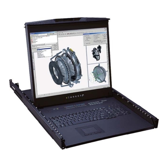
User Manual Series L-120 / LS-120 - 1U 20" LCD keyboard drawer - Resolution up to 1600 x 1200 - Full range KVM options Series W-119 / WS-119 - 1U widescreen 19" LCD keyboard drawer - Resolution up to 1440 x 900 - Full range KVM options... -
Page 2: Table Of Contents
Contents Chapter 1 Getting Started Important Safeguards............1 Regulatory Notice..............2 Package Contents...............3 Before Installation...............4 Unpacking................4 Optional Accessories............4 Peripheral Products.............5 Structure Diagram...............6 Installation..............7-12 1.10 How to Use the Slide............13 1.11 How to Use LCD Keyboard Drawer........14 1.12 LS-120 / WS-119 (Single console) ......15 - Use CB-6 to connect to server via USB interface 1.13... - Page 3 Contents Chapter 4 Optional Specifi cation KVM Options..............26 DVI-D Input Option............26 BNC + S-Video Option............26 Audio Option..............27 DC power Options............28 Chapter 5 Troubleshooting ............29 Chapter 6 Dimensions ...............30...
- Page 4 Blank page...
-
Page 5: Important Safeguards
Chapter 1 1.1 Important Safeguards Please read all of these instructions carefully before you use the device. Save this manual for future reference. What the warranty does not cover ■ Any product, on which the serial number has been defaced, modifi ed or removed. ■... -
Page 6: Regulatory Notice
Chapter 1 1.2 Regulatory Notice Legal Information First English printing, October 2002 Information in this document has been carefully checked for accuracy; however, no guarantee is given to the correctness of the contents. The information in this document is subject to change without notice. We are not liable for any injury or loss that results from the use of this equipment. -
Page 7: Package Contents
Chapter 1 1.3 Package Contents LCD keyboard drawer x 1 pc CB-6 USB 2-in-1 KVM cable x 1 pc (for LS / WS series) CE-6 Combo 4-in-1 KVM cable x 1 pc (for L / W series) User manual x 1 pc Power cord x 1 pc Auto switch power adapter ( for external power version) x 1 pc Mounting bracket x 2 pcs... -
Page 8: Before Installation
Chapter 1 1.4 Before Installation ■ It is very important to locate the LCD Keyboard Drawer in a suitable environment. ■ The surface for placing and fi xing the LCD Keyboard Drawer should be stable and level or mounted into a suitable cabinet. -
Page 9: Peripheral Products
Chapter 1 1.7 Peripheral Products Item Model No. Description MU-1602 / MU-1603 / MU-1604 Matrix Cat6 16 port KVM MU-IP1613 / MU-IP1614 / MU-IP1624 Matrix IP Cat6 16 port KVM Matrix Cat6 KVM MU-3202 / MU-3203 / MU-3204 Matrix Cat6 32 port KVM MU-IP3213 / MU-IP3214 / MU-IP3224 Matrix IP Cat6 32 port KVM M-802 / M-803 / M-804... -
Page 10: Structure Diagram
Chapter 1 1.8 Structure Diagram L / LS series Carry handle to release the 2-pt lock Micro switch for screen auto power off 2-point lock Membrane switch (KVM option) LCD interchangeable module kit Keyboard interchangeable module kit LCD membrane 2 buttons mouse interchangeable module kit “One Man”... -
Page 11: Installation
Chapter 1 1.9 Installation For L & LS series Rear side Right bracket Left bracket Front side ■ Attach the left and right mounting bracket to rack 19" mounting rails. ■ Adjust the mounting bracket to fi t your rack. ■... - Page 12 Chapter 1 1.9 Installation Front side M3.2 screw Rear kit ■ Fix the rear kit to the mounting bracket by M3.2 screw x 4 pcs included. Caution : This step is necessary. Failure to complete this will cause damage. M3.2 screw Front side ■...
- Page 13 Chapter 1 1.9 Installation ■ Pull out the LCD tray. M6 screw M3.2 screw M6 screw ■ Tighten all M6 and M3.2 screws ( total 14 pcs ).
-
Page 14: Complete The Installation
Chapter 1 1.9 Installation Complete the installation ■ Pull and hold the left & right black arrow buttons on the rails. ■ Return the LCD tray to park position. P.10... - Page 15 Chapter 1 1.9 Installation For W & WS series Rear side Right bracket Left bracket Front side ■ Attach the left and right mounting bracket to rack 19" mounting rails. ■ Adjust the mouting bracket to fi t your rack. ■...
-
Page 16: Installation
Chapter 1 1.9 Installation Mounting bracket ■ Pick up the LCD tray. ■ Insert the LCD tray into the mounting bracket. ■ Pull and hold the left & right black arrow buttons on the rails. ■ Return the LCD tray to park position. Black arrow button ■... -
Page 17: How To Use The Slide
Chapter 1 1.10 How to Use the Slides ■ A black arrow release button is located on the outside of each slide. (shown in Figure 1). Figure 1. ■ Pull and hold the black arrow button on either side of the LCD keyboard drawer to unlock. (shown in Figure 2). -
Page 18: How To Use Lcd Keyboard Drawer
Chapter 1 1.11 How to Use LCD Keyboard Drawer ■ Press the carry handle button. Gently pull the carry handle toward the front of the LCD. (shown in Figure 4) Figure 4. Sliding out the LCD keyboard drawer by pressing the carry handle button first. -
Page 19: Use Cb-6 To Connect To Server Via Usb Interface
Chapter 1 1.12 LS-120 & WS-119 (Single console) - Use CB-6 to connect to server via USB interface Figure 7. Example of connecting CB-6 2-in-1 USB KVM cable to server via USB interface 1.13 LS-120 & WS-119 (Single console) - Use CB-6 to connect to KVM via USB interface CB-6 KVM Cable Figure 8. -
Page 20: Use Ce-6 To Connect To Server Via Ps/2 Interface
Chapter 1 1.14 L-120 & W-119 (Single console) - Use CE-6 to connect to server via PS/2 interface Figure 9. Example of connecting CE-6 4-in-1 Combo KVM cable to server via PS/2 interface 1.15 L-120 & W-119 (Single console) - Use CE-6 to connect to KVM via PS/2 interface CE-6 KVM Cable Figure 10. -
Page 21: Use Ce-6 To Connect To Server Via Usb Interface
Chapter 1 1.16 L-120 & W-119 (Single console) - Use CE-6 to connect to server via USB interface Figure 11. Example of connecting CE-6 4-in-1 Combo KVM cable to server via USB interface 1.17 L-120 & W-119 (Single console) - Use CE-6 to connect to KVM via USB interface CE-6 KVM Cable Figure 12. -
Page 22: On-Screen Display Operation
Chapter 2 2.1 On-screen Display Operation LCD membrane Membrane Switch Function Power light Green = On Orange = Power saving Power on / off LCD Display the OSD menu Scrolls through menu options and adjusts the displayed control (To auto adjustment by pressing the button for 5 seconds) Exit the OSD screen Toggle analog, digital &... -
Page 23: On-Screen Menu
Chapter 2 2.2 On-screen Menu OSD Confi guration Page Image: To enter into the brightness, contrast, color temp, red, green, and blue Geometry: To enter into the auto adjust, H position, V position, phase and clock Video: To enter into the colour, tint, sharpness, noise reduction, DCDi and TV Setup Audio: To enter into volume, bass, treble, balance, AVL and mute... -
Page 24: Specifi Cations
Chapter 3 3.1 L & LS series Specifi cations Item Description 1U rack mounting on slide-out rails Form Factor LCD Manufacturer Series 20" TFT 20" TFT Diagonal Size 1152 x 900 (Direct) 1600 x 1200 Max. Resolution 1600 x 1200 (Native) Brightness (cd/m²) 16.7 M 16.7 M... -
Page 25: Specifi Cations
Chapter 3 3.1 W & WS series Specifi cations Item Description 1U rack mounting on slide-out rails Form Factor LCD Manufacturer Series Wide 19" TFT Wide 19” TFT Diagonal Size 1152 x 900 (Direct) 1440 x 900 Max. Resolution 1440 x 900 (Native) Brightness (cd/m²) 16.7 M 16.7 M... -
Page 26: Keyboard & Mouse
Chapter 3 3.2 Keyboard & Mouse For L-120 series Supporting layouts N keyboard integrated with touchpad & 2 buttons mouse interchangeable module kit P.22... - Page 27 Chapter 3 3.2 Keyboard & Mouse For W-119 series Supporting layouts N keyboard integrated with touchpad N keyboard integrated with trackball P.23...
-
Page 28: Keyboard & Mouse
Chapter 3 3.2 Keyboard & Mouse For LS-120 & WS-119 series Supporting layouts NS keyboard integrated with touchpad ■ Incorporates SUN keys, including Stop, Cut, Paste, Compose, Copy and Help ■ 104 key notepad keyboard with full numerical pad and SUN function ■... -
Page 29: How To Use "Ns" Keyboard
Chapter 3 3.3 How to Use "NS" keyboard ■ NS SUN-compatible keyboard incorporates SUN short-cut keys. ■ Press the Fn/Num button to switch the color the Num LED. Num LED in Off mode Num LED in Green color Key pad behaves as a SUN Solaris system Key pad behaves as a normal key pad mode administration command mode Three Audio / Display keys are located in the upper-right corner of the NS keyboard:... -
Page 30: Kvm Options
Chapter 4 4.1 KVM Options Our KVM is designed to seamlessly integrate into the rear of our full range of LCD drawer solutions: ■ For KVM operation, please refer to KVM user manual ■ Option with Multiple consoles Matrix KVM ■... -
Page 31: Audio Option
Chapter 4 4.4 Audio Option Speaker 3-in-1 VGA KB mouse Power Audio console port Remarks ■ Audio input is 35mm audio plug ■ The speaker is sharing the same power with LCD. P.27... -
Page 32: Dc Power Options
4.5 DC Power Options Model Input rating Input voltage: 12-Volt 24-Volt 48-Volt Input range: 9 ~ 18V 18 ~ 36V 36 ~ 75V Input current - No load 50 mA 50 mA 50 mA - Full load 4950 mA 2450 mA 1220 mA Output rating Output voltage:... -
Page 33: Chapter 5 Troubleshooting
Chapter 5 5.1 Troubleshooting 1. Is interference signal appeared on LCD normal when shutting down the computer ? In rare cases, interference may appear on the monitor. This may be caused by signal rate of VGA card and is considered normal. -
Page 34: Chapter 6 Dimensions
Weight Weight 442 x 650 x 44 mm 589 x 856 x 168 mm 20 kg 26 kg L-120 series 17.4 x 25.6 x 1.73" 23.2 x 33.7 x 6.6" 44 lb 57 lb 442 x 650 x 44 mm... - Page 35 Blank page...
- Page 36 The company reserves the right to modify product specifi cations without prior notice and assumes no responsibility for any error which may appear in this publication. All brand names, logo and registered trademarks are properties of their respective owners. Copyright 2010 Austin Hughes Electronics Ltd. All rights reserved. CV-LW38-0610V3...
Need help?
Do you have a question about the L-120 series and is the answer not in the manual?
Questions and answers