Table of Contents
Advertisement
Advertisement
Table of Contents

Subscribe to Our Youtube Channel
Related Manuals for Craftex CT146


Summary of Contents for Craftex CT146
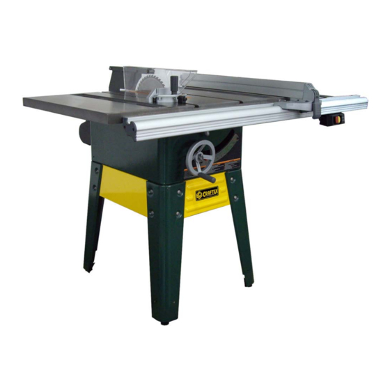
- Page 1 CT146 – 10” TABLE SAW...
-
Page 2: Table Of Contents
INDEX GENERAL SAFETY INSTRUCTIONS…………………………………………………………PAGE 3 SPECIFIC SAFETY INSTRUCTIONS……………………………………………………….PAGE 4-6 Grounding Information……………………………………………………………………………PAGE 7 Changing from 110V to 220V……………………………………………………………………PAGE 8 Introduction & Features…………………………………………………………………………..PAGE 9 Loose Parts Diagram…………………………………………………………………………PAGE 10-11 ASSEMBLY INSTRUCTIONS Removing Hardware & Parts……………………………………………………………..……..PAGE 12 Assembly of Legs & Stand…………………………………………………………..…….PAGE 13 – 14 Mounting the Table to Stand…………………………………………………………………….PAGE 15 Installing the Extension Tables………………………………………………………………….PAGE 16 Installing the Bevel Adjusting Hand Wheel…………………………………………………….PAGE 17... -
Page 3: General Safety Instructions
GENERAL SAFETY INSTRUCTIONS Extreme caution should be used when operating all power tools. Know your power tool, be familiar with its operation, read through the owner’s manual and practice safe usage procedures at all times. • CONNECT your machine ONLY to the matched and specific power source. •... -
Page 7: Grounding Information
GROUNDING To prevent possible electrical hazards, have a qualified electrician ensure that the line is properly wired. This machine is pre-wired to be use with a 120 volt power supply and ensure the cord is plugged into a grounded power outlet. -
Page 8: Changing From 110V To 220V
CHANGING FROM 110V TO 220V This table saw is pre-wired for 110V, 60 Hz. The following diagrams will help explain the procedure to change over from 110V to 220V. The use of a qualified technician is needed for this procedure. First, unplug the saw. -
Page 9: Introduction & Features
INTRODUCTION As part of a growing line of Craftex Woodworking Equipment, we are proud to introduce the CT146 10” Contractors Table Saw. This is a professional woodworking tool and like all tools, proper care and safety precautions should be exercised at all times. Please read this manual and adhere to all safety rules when using this machine. -
Page 10: Loose Parts Diagram
LOOSE PARTS OF MACHINE... - Page 11 LOOSE PARTS OF MACHINE...
-
Page 12: Assembly Instructions Removing Hardware & Parts
ASSEMBLY Carefully remove the all components and place it carefully on a level and stable work surface. This tool is heavy and it is recommended that you use the help of a friend to lifting heavy components. Remove any protective oil, grease that has been applied to the unpainted metal surfaces. -
Page 13: Assembly Of Legs & Stand
ASSEMBLY Assembly of Legs & Stand Locate the following parts 15 Hex Nuts, Flanged (5/16 – 18) 15 Carriage Bolts (5/15-18 x 5/8”) 8 Hex Nuts (3/8-16) Place the front brace inside the first leg piece & align the holes on the leg piece with the front brace. - Page 14 ASSEMBLY Now you can attach the second leg piece to the other side of the front brace using another two carriage bolts and flanged hex nuts, same as show above. Repeat the above steps for the back brace and hand tighten See Figure 1 Place the left side brace inside the leg piece and align the holes on the side brace with the holes of the leg piece.
-
Page 15: Mounting The Table To Stand
Place the assembled leg stand on the table saw base. Align the holes with the holes of the legs. (The Craftex logo denotes the front of the saw and this must be used as the front face.) -
Page 16: Installing The Extension Tables
ASSEMBLY Insert a screw though the hole in the leg stand and also in the and in the saw base. Add a hex nut here and hand tighten only. Repeat for the remaining holes and tighten all hardware when complete with a wrench to ensure it is secure. -
Page 17: Installing The Bevel Adjusting Hand Wheel
ASSEMBLY Installing the Bevel Adjusting Hand wheel First, find the following loose parts 1 Bevel Hand Wheel 1 Pan Head Screw (1/4-=20 x 5/8” with washer) Place the bevel hand wheel onto the bevel shaft. Ensure that the fit is proper and slide it all the way. -
Page 18: Installing The Height Adjusting Hand Wheel
ASSEMBLY Installing the Height Adjusting Hand wheel First, remove the blade height lock knob by turning it counterclockwise. Then, slide the height adjusting hand wheel onto the rod and against the lock tube. Last, secure the height adjustment hand wheel by reinstalling the blade height lock knob. -
Page 19: Installing The Front Rail To Table
ASSEMBLY Installing the Front Rail to the Table Insert the square head bolts (5/16-18 x 1”) into the holes on the front of the saw table and extension tables. Take the flanged hex nut (5/16-18) loosely allowing the square bolt head to protrude just a little. -
Page 20: Installing The Back Rail To Table
ASSEMBLY Installing the Back Rail to the Table Insert the square head bolts (5/16-18 x 1”) into the holes on the back of the saw table and extension tables. Take the flanged hex nut (5/16-18) loosely allowing the square bolt head to protrude just a little. - Page 21 ASSEMBLY Installing the Back Rail to the Table cont… Take a framing square and place it on either side of the blade. Move the back rail right or left until you see the indicator mark is aligned with the framing square. This will give you an accurate set up.
-
Page 22: Adjusting The Front & Back Rails
ASSEMBLY Adjusting the Front & Back Rails NOTE – The front & back rails MUST be adjusted to with the saw blade. If not done properly, this may cause kickback or binding and could result in serious personal injury. Set the saw bevel to ‘0’ so that the blade is vertical and lock the bevel with the lever above the blade height wheel. -
Page 23: Installing The Rip Fence
ASSEMBLY Install the Rip Fence Place the front of the fence on the front rail. Lower the back end of the fence onto the back rail. It should sit smooth and should glide smoothly. Lock the fence by pushing down on the locking handle and this should automatically align the fence. -
Page 24: Aligning The Throat Plate
ASSEMBLY Ensure that the rip fence is not too high or too low off the table top. You will want it to be just about a millimeter off the base of the table. To adjust, loosen the hex nuts holding the rails in place and adjust the rails up or down as needed. Once proper alignment is made, tighten down all the hex nuts. -
Page 25: Installing The Spacer Bar
ASSEMBLY Installing the Spacer Bar Locate the following loose parts 1 – Spacer Bar 2 – Set Screws 2 – Support Plates Take one of the set screws and thread it into the locking plate. Place one support plate over each end of the spacer bar and ensure the bent ends are pointing out. -
Page 26: Installing The Blade Guard Assembly
ASSEMBLY Installing the Blade Guard Assembly To install the blade guard assembly, lower the blade by turning the adjusting hand wheel on a counterclockwise direction. Attach the separator to the separator support and align the edges. Now, secure using the flanged nuts (1/4-20) and hex head screws (1/4-20 x 5/8”). Tighten with a wrench. -
Page 27: Aligning The Blade Guard Assembly & The Blade
ASSEMBLY Aligning the Blade Guard Assembly and the Blade First, raise the saw blade by turning the hand wheel in a clockwise direction. With the use of a combination or framing square, place the square against the saw blade and the blade guard assembly as show in Figure 15 This should give you an idea of if the blade guard is square to your blade which is important. -
Page 28: Mounting The Motor Assembly
ASSEMBLY Mounting the Motor Assembly You will need to mount the motor to the back of saw. To do so, first loosen the 2 hex head screws that lock the pins in the mounting brace. At this point, insert the 2 pins on the motor assembly into the holes on the mounting brace. -
Page 29: Installing The Belt Guard
ASSEMBLY Installing the Belt Guard Locate the following from the loose parts 1 – Belt Guard 4 – Flat Washers (M5.3 x 12 x 1) 4 – Flanged Hex Nuts (M5 x .8) Lower the blade by turning the blade height hand wheel in a counterclockwise direction and remove the belt. -
Page 30: Installing The Belt
ASSEMBLY Installing the Belt First, lower the blade by turning the blade height hand wheel in a counterclockwise direction and set the bevel to ‘0’. Now, place the belt on the saw pulley and the motor pulley. Check along both pulleys to make sure the belt is parallel to the edges of both pulleys. -
Page 31: Installing The Switch Assembly
ASSEMBLY Installing the Switch Assembly The switch assembly can be mounted on either side of the fence (left or right) depending on your preference. Locate the following from the loose parts 1 Switch Key 2 Square Nuts (10-32) 2 Pan Head Screws with Lock Washers (10-32 x 3/8”) Insert the pan head screws with the lock washers through the holes in the switch assembly. -
Page 32: Securing The Electrical Cords
ASSEMBLY Secure Electrical Cords Your saw is supplied with 3 wire ties (one is extra) to secure the power cords of your saw. This is helpful aid to get the lines out of the way. The motor cord and power cord should be gathered together along the side of the cabinet and the two holes on the side of the cabinet are used to secure the wire ties. -
Page 33: Installing The End Caps Of Fence
ASSEMBLY Installing the End Caps of the Fence Align the end caps of the front rail to the end of the rail. Secure these by using a self tapping pan head screw (M4) is each hole. Do the same for the rear rails. See Figure 21 Figure 21 Congratulations, your saw should now be fully assembled and ready to take its... -
Page 34: Troubleshooting
TROUBLESHOOTING PROBLEM CAUSE SOLUTION Saw does not start Cord is not plugged in Plug Power Cord in Circuit breaker is tripped Reset Breaker Motor/switch/cord is damaged See Qualified Technician Circuit fuse is blown Replace circuit fuse PROBLEM CAUSE SOLUTION Excess Vibration Blade is damaged Replace Blade Uneven Work Surface... -
Page 35: Maintenance
MAINTENANCE General maintenance should be preformed on your saw to keep it free from problems and working in its peak condition. The following are general guidelines to help with regular maintenance. NOTE – Before performing any maintenance, UNPLUG your saw from the power source and turn the switch assembly to OFF. -
Page 36: Miter Gauge Assembly
SCHEMATIC DIAGRAM – MITER GAUGE ASSEMBLY... - Page 37 PARTS LISTING – MITER GAUGE ASSEMBLY PART NUMBER DESCRIPTION TH1006 MITRE GAUGE ASSEMBLY TH100606 HANDLE HU190400 WASHER 8.5*23*2.0 TH100601 MITRE GAUGE HU150100 HEX.NUT #6-32NC HU040101 SCREW #8-32NC*5/16" TH100604 ANGLE INDEX TH100603 INDICATOR BLOCK TH100605 LOCK ROD/PIN HU030101 SET SCREW M5*0.8P*5 HU040604 SCREW #6-32NC*5/8"...
-
Page 38: Stand Assembly
SCHEMATIC DIAGRAM – STAND ASSEMBLY... - Page 39 PARTS LISTING – STAND ASSEMBLY PART NUMBER DESCRIPTION MH060008 FOOT LEVEL HU150600 HEX. NUT 3/8"-16NC TH100069 PLATE TH260013 TH260014 REAR PLATE HU070102 SCREW 5/16"-18NC*5/8" HU170300 NUT 5/16"-18NC(12.7B*7H) TH100078 FENCE HANGER TH260002 SIDE PLATE JG1A2L01 CRAFTEX LOGO TH100072 GAUGE SUPPORTER...
-
Page 40: Rip Fence Assembly
SCHEMATIC DIAGRAM – RIP FENCE... - Page 41 LOCK PLATE OE290006 LOCK SPRING OE290005 CAM PIN HU010103 SCREW 1/4"-20NC*3/4" OE290001 FRONT HOUSING OE290016 BEARING TH101906 CRAFTEX LOGO PLATE TH101904 LOCKING LEVER SCREW W/ WASHER 1/4"- HU270101 20NC*3/4" HU180200 NUT 1/4"-20NC OE290302 MICRO ADJUSTING WHEEL HU250102 SCREW #10-32NF*1-1/4" TH101903...
-
Page 42: Blade Guard Assembly
SCHEMATIC DIAGRAM – BLADE GUARD... - Page 43 PARTS LISTING – BLADE GUARD PART NUMBER DESCRIPTION SAW BLADE GUARD TH1004 ASSEMBLY TH100401 WARNING LABEL TH100092 HU300100 RING SPN-1/4" TH100043 GUARD TH100412 NUT #10-32NF HU190200 WASHER 5.3*14*1.0 TH100044 SPLITTER TH100018 SPACE TH100065 SPRING PIN TH100046 SPRING PIN TH1010 PLATE TH100411 SCREW 3/16"-32NF*22.2mm TH100402...
-
Page 44: Motor Assembly
SCHEMATIC DIAGRAM – MOTOR ASSEMBLY... - Page 45 PARTS LISTING – MOTOR ASSEMBLY PART NUMBER DESCRIPTION TH3303 MOTOR SET ASSEMBLY HU150500 NUT 5/16"-18NC HU200400 STAR WASHER 8.4*15 TH100014 MOTOR BASE HU070101 SCREW 5/16"-18NC*1/2" HU230100 E RING ETW-8 TH100017 SPRING TH1012 MOTOR SUPPORT SET TH100045 SLEEVE HU190300 WASHER 6.7*19*1.0 HU060101 SCREW 1/4"-20NC*5/8"...
-
Page 46: Main Housing Assembly
SCHEMATIC DIAGRAM – MAIN HOUSING... - Page 47 PARTS LISTING – MAIN HOUSING PART NUMBER DESCRIPTION STAR WASHER 1/4"- HU130202 20NC*5/8" TH1001 HAND WHEEL SET HU080102 SCREW M4.5*1.81P*9 HU040203 SCREW #10-32NF*1/2" TH100010 STIFFNER PLATE TH100076 BEVEL SCALE PH1A0602 MACHINE LABEL TH100060 SCREW HU200300 STAR WASHER 6.4*11 TH100081 TIE WRAPS HU170300 NUT 5/16"-18NC HU160300...
-
Page 48: Table Assembly
SCHEMATIC DIAGRAM – TABLE ASSEMBLY... - Page 49 PARTS LISTING – TABLE ASSEMBLY PART NUMBER DESCRIPTION HU080301 SCREW M4*1.59P*12 TH100053 REAR RAIL COVER LEFT TH102102 REAR RAIL STICKER 310062-909 REAR RAIL ASSEMBLY TH100001 MAIN TABLE TH100050 THROAT PLATE TH100025 SCREW #10-32NF*1-1/4" HU140101 SET SCREW #10-32NF*3/8" TH100049 EXT. WING TH100052 REAR RAIL COVER RIGHT HU030303...
-
Page 50: Internal Body Assembly
SCHEMATIC DIAGRAM – INTERNAL BODY... - Page 51 PARTS LISTING – INTERNAL BODY PART NUMBER DESCRIPTION TH100093 WASHER 1/4"-20NC TH100063 SPRING HU191200 WASHER 6.2*19*1.0 TH100080 WASHER 10.2*19*1.6 TH100030 SCREW SLEEVE TH100003 TRUNNION HU010304 SCREW 3/8"-16NC*1" TH100021 HANDLE HU010305 SCREW 3/8"-16NC*1-3/8" SAW BLADE 40T TH100023 SAW BLADE WASHER TH100079 SAW BLADE NUT TH1014 SIDE COVER SET...
- Page 52 HU220100 WAVE WASHER WW-16 HU190800 WASHER 16*25*1.5 HU230200 E RING ETW-12 TH1013 ARBOR SET TH100002 ARBOR BASE TH100012 ARBOR TH100011 STOP PIN HU120101 WASHER 3/16"-24NC*1/2" TH100034 HOSE TH100090 WASHER 20.1*35*2.0 HU230300 E RING ETW-15 HU190500 WASHER 10.3*22*2.0 TH100006 PULLY HU240100 S RING STW-15 HJ036300 BEARING 6202-2NSE...
-
Page 53: Warranty Information
RETURNS, REPAIRS AND REPLACEMENTS To return, repair, or replace a Craftex product, you must visit the appropriate Busy Bee Tools showroom or call 1-800- 461-BUSY. Craftex is a brand of equipment that is exclusive to Busy Bee Tools. For replacement parts directly from Busy Bee Tools, for this machine, please call 1-800-461-BUSY (2879), and have your credit card and part number handy.
Need help?
Do you have a question about the CT146 and is the answer not in the manual?
Questions and answers