
Related Manuals for Advantech PPC-3060S


Summary of Contents for Advantech PPC-3060S
- Page 1 User Manual PPC-3060S Intel® Celeron® N2807 Processor based panel PC, with 6.5" color TFT LCD display...
- Page 2 No part of this manual may be reproduced, copied, translated or transmitted in any form or by any means without the prior written permission of Advantech Co., Ltd. Information provided in this manual is intended to be accurate and reliable. How- ever, Advantech Co., Ltd.
-
Page 3: Declaration Of Conformity
This product has passed the CE test for environmental specifications when shielded cables are used for external wiring. We recommend the use of shielded cables. This kind of cable is available from Advantech. Please contact your local supplier for ordering information. -
Page 4: Safety Instructions
The sound pressure level at the operator's position according to IEC 704-1:1982 is no more than 70 dB (A). DISCLAIMER: This set of instructions is given according to IEC 704-1. Advantech disclaims all responsibility for the accuracy of any statements contained herein. - Page 5 Do not attempt to recharge, force open, or heat the battery. Replace the battery only with the same or equivalent type recommended by the man- ufacturer. Discard used batteries according to the manufacturer's instructions. Note! Notes provide optional additional information. PPC-3060S User Manual...
- Page 6 PPC-3060S User Manual...
-
Page 7: Table Of Contents
......1 Introduction ....................2 Features ....................2 Front Panel....................2 Figure 1.1 Front panel of PPC-3060S ......... 2 Rear Panel ....................3 Figure 1.2 Rear panel of PPC-3060S .......... 3 Bottom Side....................3 Figure 1.3 Bottom side of PPC-3060S......... 3 Dimensions .................... - Page 8 SATA Mode Selection..............42 4.2.9 Boot Options ................43 Appendix A BSMI RoHS ........45 BSMI RoHS..................... 46 Appendix B China ROHS........47 China ROHS ................... 48 Appendix C Watchdog Timer Programming Example49 Watchdog Timer Programming Example ..........50 PPC-3060S User Manual viii...
-
Page 9: Chapter 1 General Information
Chapter General Information This chapter gives background information on PPC-3060S panel Sections include: Introduction Specifications Dimensions... -
Page 10: Introduction
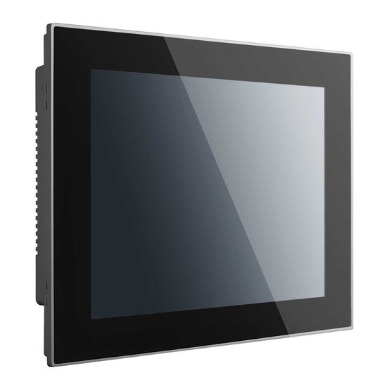
Optional Mini PCIe 802.11b/g/n wireless module Supports one USB 3.0 Front Panel The front side of PPC-3060S is a flat panel LCD with touch screen, which provides IP65 protection. (Figure 1.1) Figure 1.1 Front panel of PPC-3060S PPC-3060S User Manual... -
Page 11: Rear Panel
Rear Panel There are four VESA 75x75mm mounting holes and several retention screw holes on rear panel.(Figure 1.2). Figure 1.2 Rear panel of PPC-3060S Bottom Side The following interfaces on bottom side are: (Figure 1.3) 1 x Power input connector ... -
Page 12: Dimensions
Dimensions Figure 1.4 PPC-3060S Dimension PPC-3060S User Manual... -
Page 13: Specifications
Operating random vibration test, 5 ~ 500Hz, 1Grms with HDD; Vibration 2Grms with SSD, following IEC 60068-2-64 Front Mask IP level IP65 Safety: CB, UL, CCC, BSMI Safety and EMC EMC: CE, FCC Class B, BSMI Dimensions 197.6 x 150.6 x 41 mm Weight 1.5 kg PPC-3060S User Manual... -
Page 14: Ordering Information
Panel PC with Intel Celeron® N2807 PPC-3060S-N80AE processor Bracket model for 2.5" SSD/HDD instal- 98R3P30600E lation Power adapter AC100 ~ 240V, 90W, 96PSA-A90W19OT-1 PPC-WLAN-A1E WiFi module with antenna PPC-ARM-A03 ARM VESA standard PPC-174T-WL-MTE Wall mount kit PPC-Stand-A1E Stand kit PPC-3060S User Manual... -
Page 15: Chapter 2 System Installation & Setup
Chapter System Installation & Setup Sections include: Quick Installation Guide Install Memory Card Install HDD Install mSATA Install Wireless LAN Card Mounting the System... -
Page 16: Quick Start Guide
When you place the panel PC upright on the desktop, its front panel appears as shown in Figure 2.1, Frontside View, Figure 2.2 Backside View, and Figure 2.3 I/O Connectors. Figure 2.1 Frontside View Figure 2.2 Backside View PPC-3060S User Manual... -
Page 17: Installing Procedures
Install SATA HDD or mSATA storage. Install peripheral devices. Mount the Panel PC. Configure the system. 2.2.1 Installing Memory Card Remove 4 screws and 4 stands (See Figure 2.4) and take off the rear cover. Figure 2.4 Retention Screws on Rear Cover PPC-3060S User Manual... -
Page 18: Figure 2.5 Installation Of Memory Card
(See Figure 2.5 and 2.6) Figure 2.5 Installation of Memory Card Figure 2.6 Attaching the Thermal Pad on the Memory Warning! Please make sure the thermal pad (in the accessory box) is attached on the memory surface as in figure 2.6. PPC-3060S User Manual... -
Page 19: Install Hdd
2.2.2 Install HDD Pick up materials from HDD module (Advantech part number: 98R3P30600E), including HDD brackets, cable and screws (See Figure 2.8). Then remove the pre installed four retention screws on the HDD bracket. (See Figure 2.7) Figure 2.7 Retention Screws on the HDD Bracket... -
Page 20: Figure 2.8 Hdd Module
Figure 2.8 HDD Module Get the SATA cable from the accessory box and connect it to the SATA HDD. (See Figure 2.9) Figure 2.9 Connection of Cable and SATA HDD PPC-3060S User Manual... -
Page 21: Figure 2.10Installing The Hdd Into The Hdd Cover
Position it into the HDD cover. (See Figure 2.10) Figure 2.10 Installing the HDD into the HDD cover Loosen the screws on the mSATA door (See Figure 2.11), then remove the mSATA door. Figure 2.11 Removing the mSATA Door PPC-3060S User Manual... -
Page 22: Installing Msata
Loosen the screws on the mSATA door (See Figure 2.11), then remove the mSATA door. Place the mSATA card into the socket, push the other end of the mSATA card down and secure the mSATA module with the two retention screws in the acces- sory box. (See Figure 2.14) PPC-3060S User Manual... -
Page 23: Installing Wireless Lan Module
First refer to Figure 2.4, Retention Screws on Rear Cover and take off the rear cover. 2.2.4.1 Full-size card mini PCIe installation Insert the Mini PCIe full-size card into socket, and secure the card with the two retention screws in the accessory box. (See Figure 2.15) PPC-3060S User Manual... -
Page 24: Figure 2.15Install Full-Size Wireless Lan Card
Get the hexagonal screw from the accessory box, locate it in the notch on the PCB and secure it. (See Figure 2.16) Figure 2.16 Location of Retention Screws Insert the mini PCIe half-size card into the socket at an angle, and secure with a screw from the accessory box.(See Figure 2.17) PPC-3060S User Manual... -
Page 25: Figure 2.17Install Half-Size Wireless Lan Card
Figure 2.17 Install Half-size Wireless LAN Card Install the antenna. (See Figure 2.18 and Figure 2.19) Figure 2.18 Antenna Cables of Full-size mini PCIe LAN Module PPC-3060S User Manual... -
Page 26: Mounting The System
Select the location on the wall for the wall mounting bracket. Mark the locations of the two screws holes in the bracket on the wall. Drill two pilot holes at the marked locations on the wall Align the wall-mounting bracket screw holes with the pilot holes. PPC-3060S User Manual... -
Page 27: Figure 2.20Mounting The Bracket On The Wall
Figure 2.21 Location of the Four Screws on the Rear Panel Warning! Please make sure the thread depth of the screw for rear panel should be no more than 4mm. Align the Panel PC into the mounting bracket on the wall. (Figure 2.22) PPC-3060S User Manual... -
Page 28: Panel Mounting
Figure 2.23 Secure the Panel PC 2.3.2 Panel Mounting To mount the flat bezel panel PC into a panel, please follow the steps below. Cut out a section corresponding to the size shown below. The dimensions are in mm. (See Figure 2.24) PPC-3060S User Manual... -
Page 29: Figure 2.24Ppc-3060S Cut-Out Dimensions
Figure 2.24 PPC-3060S Cut-out Dimensions Put the machine into the cabinet and take out the eight hook brackets from the accessory box. (See Figure 2.25) Figure 2.25 Hook Brackets for Panel Mounting Put the hook brackets into the holes according to the arrow and hookup the machine. -
Page 30: Figure 2.26Hook Bracket Locations
Figure 2.26 Hook Bracket Locations Lock screws and fixed machine. (See Figure 2.27) Figure 2.27 Fasten the Hook Bracket See finished view. (See Figure 2.28) Figure 2.28 Back-side View of Panel Mounting PPC-3060S User Manual... -
Page 31: Arm Mounting
2.3.3 Arm Mounting PPC-3060S is a VESA compliant panel PC and can be mounted on an arm with a 75mm interface pad. To mount PPC-3060S on an arm, please follow the steps below. Refer to the installation instruction of the mounting arm to correctly mount the arm onto the surface as a base. -
Page 32: Stand Mounting
As shown in the figure below use four No. A screws in the packing list to lock the VESA BKT to the machine. Depending on your needs, you can choose between using 75*75 mm or 100*100 mm of VESA mount. Figure 2.30 Screw Holes PPC-3060S User Manual... -
Page 33: Figure 2.31Securing The Base
As the figure below shows, use four No. A screws in packing list to lock on the base plate. Figure 2.31 Securing the Base As the figure below shows use four No. B screws in the packing list to secure the VESA Bracket. Figure 2.32 Securing VESA Bracket PPC-3060S User Manual... -
Page 34: Figure 2.33Securing The Hinge Cover
As the figure below shows, use one No. C screw in the packing list to secure the hinge cover. Figure 2.33 Securing the Hinge Cover Completed view of stand mounted PPC machine Figure 2.34 Secured Hinge Cover PPC-3060S User Manual... -
Page 35: Jumper Setting
Chapter Jumper Setting Sections include: Jumper & Connectors External COM Ports and Pin Definitions... -
Page 36: Motherboard Layout Diagram
LVDS power select jumper Pin header 3P 2.54mm RTC select jumper Pin header 4P 2.0mm ATX/AT select jumper Pin header 3P 2.0mm LVDS PWM power select jumper Pin header 3P 2.0mm LVDS enable power select jumper Pin header 3P 2.0mm PPC-3060S User Manual... -
Page 37: Lvds Power Select Jumper
LVDS PWM Power Select Jumper (1-2) (2-3) 3.3V Default* 3.2.3 LVDS enable power select jumper Icon LVDS Enable Power Select Jumper (1-2) (2-3) 3.3V Default* 3.2.4 RTC select Icon RTC Select (2-3) Normal Default* (3-4) Clear CMOS PPC-3060S User Manual... -
Page 38: Com1 Pin 9 Select
3.2.5 COM1 Pin 9 select CN17 Icon COM1 PIN9 Power Select (1-2) COM1 RI Default* (2-3) COM1 PIN9 5V (4-5) COM1 PIN9 12V 3.2.6 ATX/AT select Icon ATX/AT Select (1-2) (2-3) Default* PPC-3060S User Manual... -
Page 39: External Com Ports And Pin Definitions
COM1 Pin9 is set as RI signal by default and also can be set as 5 V or 12 V output via jumper setting. COM2: RS232/422/485 Note! COM2 does not support RING function. COM1 COM2 RS232 RS232 RS422 RS485 DATA- DATA+ RING or 5V/12V Output RING PPC-3060S User Manual... - Page 40 PPC-3060S User Manual...
-
Page 41: Software Setup
Chapter Software Setup Sections include: Installing ng Drivers BIOS Setup Program... -
Page 42: Installing Divers
When entering the BIOS menu, select "Advanced → Security configuration → TXE HMRFPO → enable". Restart the computer. Execute AFUDOS 8211BIOS.bin /P /B /N /X /ME. Power on the system again after it is powered off. The BIOS is then updated. PPC-3060S User Manual... -
Page 43: Entering Bios Setup
When the power is turned on, press the <Del> button to enter BIOS setup screen. Whenever a change is made, press <F4> to save and exit; otherwise the settings will not be saved in the BIOS. 4.2.3 Adjustment of LCD Brightness Select “Host Bridge” in “Chipset” tab. PPC-3060S User Manual... - Page 44 Then select “Intel IGD Configuration”. Select “Brightness Manual Control” and there will be six brightness levels to choose from. PPC-3060S User Manual...
-
Page 45: Com2 Mode Selection (Rs232/Rs422/Rs485)
4.2.4 COM2 Mode Selection (RS232/RS422/RS485) Select “NCT5523D Super IO Configuration” in the “Advanced” tab. Select "Serial Port 2 Configuration" and then click PPC-3060S User Manual... - Page 46 Select "Serial Port 2 Mode" and then click to select COM2 operation mode [RS232] or [RS422] or [RS485]. When COM2 Mode is selecting RS485, “Auto Flow Control” also can select [Enabled] or [Disabled] PPC-3060S User Manual...
-
Page 47: Os Selection
When COM2 Mode is selecting RS485, “Serial Port2 Terminal” also can select [Enabled] or [Disabled] 4.2.5 OS Selection Select "South Bridge" in the "Chipset" tab. PPC-3060S User Manual... -
Page 48: Bios At & Atx Setup
Different OS can be selected through “OS Selection” [Windows 7]/[Android]/ [Windows 8.X] Note! “OS Selection" is preset as Windows 7, which needs to be changed when Windows 8.x or Android OS is installed. 4.2.6 BIOS AT & ATX Setup Select "South Bridge" in the "Chipset" tab. PPC-3060S User Manual... -
Page 49: Wake On Lan
In “Restore AC Power Loss”, set “Power On” to “AT” and “Power Off” to “ATX”. 4.2.7 Wake on LAN Select "South Bridge" in the "Chipset" tab. PPC-3060S User Manual... -
Page 50: Sata Mode Selection
Set “Wake on Function” to “Enabled”. 4.2.8 SATA Mode Selection Select "IDE Configuration" in the "Advanced" tab. PPC-3060S User Manual... -
Page 51: Boot Options
Select “SATA Mode”. 4.2.9 Boot Options Select "CSM Configuration" in the "Advanced" tab. PPC-3060S User Manual... - Page 52 Select “Boot option filter”. Note! Boot option is set as “Legacy only” by default. If “UEFI only” is selected, only Windows 7 64bits or Windows 8.x 64bits can be supported. If UEFI 32bit OS is required, please update BIOS. PPC-3060S User Manual...
-
Page 53: Bsmi Rohs
Appendix BSMI RoHS... -
Page 54: Bsmi Rohs
BSMI RoHS 設備名稱:電腦 型號 (型式) :PPC-3060S series Equipment name Type designation (Type) 限用物質及其化學符號 Restricted substances and its chemical symbols 多溴聯苯 六價鉻 多溴二苯醚 單元 Unit Polybromina 鎘 Hexavalent Polybrominate 鉛 Lead 汞 Mercury Cadmium chromium d diphenyl (Pb) (Hg) (Cd) biphenyls... -
Page 55: Appendix B China Rohs
Appendix China ROHS... -
Page 56: China Rohs
China ROHS Dear Customer, Thanks for choosing Advantech Product, to comply with China Electronic Industry Standard SJ/T11364 which require Marking for the Restriction of the Use of Hazard- ous Substances in Electrical and Electronic Products, herein report to you product’s... -
Page 57: Watchdog Timer Programming
Appendix Watchdog Timer Programming Example... -
Page 58: Watchdog Timer Programming Example
OUT DX, AL ;set WDT active ;----------------------------------------------------------------------------- ;initial WDT mode ;----------------------------------------------------------------------------- MOV DX, 2EH MOV AL, F0H OUT DX, AL MOV DX, 2FH MOV AL, 00H ; bit0: 0-Pulse Mode, 1- Level mode; bit3: 0- second mode, 1- minute mode; PPC-3060S User Manual... - Page 59 OUT DX, AL MOV DX, 2FH MOV AL, 05H OUT DX, AL ;set time-out value is 5s; 00- time-out disable ;----------------------------------------------- ; Exit the Extended Function Mode ;---------------------------------------------- MOV DX, 2EH MOV AL, AAH OUT DX, AL PPC-3060S User Manual...
- Page 60 No part of this publication may be reproduced in any form or by any means, electronic, photocopying, recording or otherwise, without prior written permis- sion of the publisher. All brand and product names are trademarks or registered trademarks of their respective companies. © Advantech Co., Ltd. 2016...
Need help?
Do you have a question about the PPC-3060S and is the answer not in the manual?
Questions and answers