Table of Contents
Advertisement
Quick Links
Advertisement
Table of Contents

Subscribe to Our Youtube Channel
Related Manuals for Zebex Z-6181


Summary of Contents for Zebex Z-6181
- Page 1 Dual-Laser Omnidirectional In-Counter Scanner...
- Page 3 Revision History Changes to the original manual are listed below: Version Date Description of Version July. 20, 2010 Initial release March. 21, 2011 Added EAS connection Dual-Laser Omnidirectional In-Counter Scanner...
- Page 4 Important Notice No warranty of any kind is made in regard to this material, including, but not limited to, implied warranties of merchantability or fitness for a particular purpose. We are not liable for any errors contained herein or incidental or consequential damages in connection with furnishing, performance or use of this material.
- Page 5 Laser Safety The Dual-Laser Omnidirectional In-Counter Scanner complies with safety standard IEC 60825 for a Class I laser product. It also complies with CDRH as applicable to a Class IIa laser product. Avoid long term staring into direct laser light. Radiant Energy: The Advanced Dual-Laser Omnidirectional In-Counter Scanner uses two low-power visible laser diodes operating at 650nm in an opto-mechanical scanner resulting in less than 3.9µW radiated power as observed through a 7mm aperture and averaged over 10 seconds.
-
Page 6: Table Of Contents
Table of Contents Important Notice ........................ii Introduction ..........................1 Key Features ........................1 Unpacking ........................2 Cable Installation......................6 Connection..........................7 Connecting Power ......................7 Verifying Scanner Operation ..................7 Connecting to the Host ....................8 Installation ..........................12 Pre-Installation Considerations ..................12 Installing the Scanner to the Counter................ -
Page 7: Introduction
’ ANUAL Introduction The Dual-Laser Omnidirectional In-Counter Scanner is a powerful scanning solution specially designed for high-traffic environments with limited space. It features dual-laser technology that enables 32 scan lines to achieve enhanced speed and accuracy, but manages to do so in a unit that measures significantly less in size than comparable scanners. -
Page 8: Unpacking
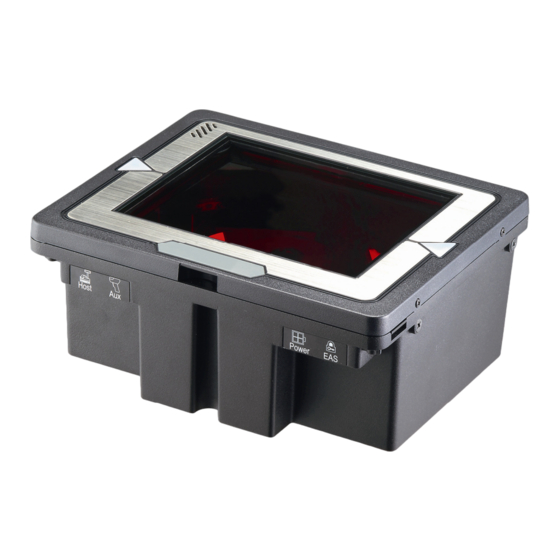
’ ANUAL Unpacking The omnidirectional scanner package contains: 1 ea. Advanced dual-laser omnidirectional in-counter scanner 1 ea. Interface cable (This cable is usually, but not always, supplied. Model depends on customer needs.) 1 ea. Power supply & power cord (Model depends on electrical requirements of your geographic location) 1 ea. - Page 9 ’ ANUAL Components Top View Figure 1: Scanner Top View Description Function Scan Window Laser aperture Speaker Exit Beep tone indication LED Indicator *2 Indicating reading status and package flow Round Screw * 4 Fixing the top plate to the scanner Flat Screw *4, M4*0.7 For vertical flush mounting Dual-Laser Omnidirectional In-Counter Scanner...
- Page 10 ’ ANUAL Bottom View Figure 2: Scanner Bottom View Description Function Carrying information such as model name and serial Device Label number EAS Port Electronic article surveillance connection Power Input External AC power input Host Port Interface communication connection to the host Connecting an auxiliary peripheral device, usually a 10 AUX Port handheld scanner...
-
Page 11: Scanner Labels
’ ANUAL Scanner Labels On the device bottom is a label containing information such as model name, serial number, and power requirement. In addition, two caution labels of laser safety are located under the window glass. Below are examples of the labels. Device Label Sample Figure 3: Device Label Caution Label Sample... -
Page 12: Cable Installation
’ ANUAL Cable Installation The scanner is to be connected to a host (e.g. POS) with the use of external power required. The scanner also supports an auxiliary scanner and EAS application. The figure below gives you an overview of the cable installation. Figure 5: Cable Installation Dual-Laser Omnidirectional In-Counter Scanner... -
Page 13: Connection
’ ANUAL Connection Connecting Power The power supply provides +12 volts, -12 volts and +5 volts DC voltage to the scanner; the detailed power requirement is as below: Voltage AC100~240 Frequency 50~60HZ Current (RMS) 600mA Output +5V,+12V,-12V A power cord is required to connect the electrical outlet and power supply. Select the proper IEC power cord for your country. -
Page 14: Connecting To The Host
’ ANUAL If the scanner is connected to a keyboard wedge for this test, it should read one barcode, beep, and the LED remain red. This is normal when the keyboard wedge is not connected to a live host terminal. The LED would flash red and read no barcode if the scanner is programmed in USB interface but not connected to a host device. - Page 15 ’ ANUAL Interface Cable Replacement The standard interface cable is attached to the scanner with a 10-pin modular connector. When properly seated, the connector is secured in the scanner bottom by a flexible retention tab. You can easily replace the communication cable and set up the interface via programming.
- Page 16 ’ ANUAL Return to PC/AT default This barcode allows setting as keyboard wedge interface for IBM PC AT/PS/2 and compatibles. Cover the unwanted barcode to ensure that the scanner read the desired barcode only. Return to RS-232 default The RS-232C interface scanner is often used when connecting to the serial port of a PC or terminal. Dual-Laser Omnidirectional In-Counter Scanner...
- Page 17 ’ ANUAL Return to USB default Reading of “Return to USB default” sets the device into USB interface support. Cover the unwanted barcode to ensure that the scanner read the desired barcode only. Return to Wand Emulation Default Available only for spe ial firmware version. Dual-Laser Omnidirectional In-Counter Scanner...
-
Page 18: Installation
’ ANUAL Inst allation Pre-Installation Considerations Before mounting the scanner, some considerations are as below: 1. Determine the direction of package flow for your pplication. Locate the optimum scanner position in the counter surface. Pay attention to the product flow, distance to the counter edge and convenience for the operator. - Page 19 ’ ANUAL Shelf Mounting You can build a shelf under the counter sur face to support the unit. Refer to the following figure for the dimensions o f the opening. Figure 6: Shelf Mounting Dual-Laser Omnidirectional In-Counter Scanner...
- Page 20 ’ ANUAL Horizontal Flush Mounting-1 There are two methods of horizontal flush mounting. You can use two metal plates to fix the scanner to the counter surface. The following figures specify dimensions of the opening, plate and screw. Contact your dealer for procurement of the mounting accessories. 235.0mm 198.0mm Fixing Plate*...
- Page 21 ’ ANUAL Figure 8: F ing Plate Dual-Laser Omnidirectional In-Counter Scanner...
- Page 22 ’ ANUAL You can also design the counter top as the following structure and simply put the device into the desired position without plates. Figure 9: Horizontal Flush Mounting-2 Dual-Laser Omnidirectional In-Counter Scanner...
- Page 23 ’ ANUAL Figure 10: Dimensions of the Opening for Horizontal Flush Mounting-2 Dual-Laser Omnidirectional In-Counter Scanner...
- Page 24 ’ ANUAL Vertical Flush Mounting nsidering different counter space and placement, the scanner can also be mounted rtically. The following figures indicate the cutout dimension and mounting quirement. 4-ø4.2 (Screw, M4x0.7) 235.0mm 195.0mm 23.5mm 47.5mm 120.0mm Φ4.2mm (9.25) (7.68”) (0.93”) (1.87”) (4.72”) (0.17”)
-
Page 25: Auxiliary Handheld Scanner Connection
’ ANUAL Auxiliary Hand held Scanner Connection Auxiliary Port The scanner provides an auxiliary port for the use of an additional peripheral device to be connected to the host system via the scanner itself. It is usually used to connect a handheld scanner for items too large to place on the checkstand. -
Page 26: Eas Connection
’ ANUAL EAN-13 identifier code EAN-8 identifier code Codabar identifier code Code 128 identifier code Code 93 identifier code MSI identifier code GS1 CodeBar Omnidirectional identifier code GS1 CodeBar Limited identifier code GS1 CodeBar Expanded Industrial 2 of 5 identifier code Code 11 identifier code Standard 2 of 5 identifier code Matrix 2 of 5 identifier code... - Page 27 ’ ANUAL Enter/Exit Programming Mode Scan t his barcode to enter the se t-up or to exit after the set-up is finished. The LED would remai n red when in programmi ng mode. Setting EAS Interlock When enabled, the EAS tag is not de-activated until the associated barcode is decoded. hen disabled (default), the EAS tag is de-activated independently of any barcod scanning.
- Page 28 ’ ANUAL Setting EAS Timeout Use this setting to set EAS Timeout. EAS output signal is held in its active state for a good read indication. To set the timeout: Scan the Enter/Exit Programming barcode to begin the setup. Scan 3 ASCII number barcodes (Please see Programming Guide) to set the time in millisecond.
-
Page 29: Window Glass Replacement
’ ANUAL Window Gla ss Replacement Since scratches on the glass of top plate windows would undermine scanning performance, occasional replacement of the window glass may be necessary. For glass replacement, there are three types of glass available: Anti-scratch coating tempered float glass, Glass with demand-like co ating (DLC) and Sa hire on Glass. - Page 30 ’ ANUAL Loosen the eight flat screws on the glass holde r; take off the glass holder and seal rubber from the front cover. The glass lies on t he front cover. Take the glass from the front cover, replace with a new one, put back the seal rubber and gla ss holder, and at last, tighten the eight screws.
-
Page 31: Set Up
’ ANUAL t Up figuring the Scanner The scanner is either pre-progr ammed to suit the situation, or it automatically detects and is ready to go. In certain cases no setup is required. In other cases the scanner must be informed about what kind of system it is connected to. This can be done in a few moments using the programming barcodes in the separate Programming Guide. - Page 32 Parameter Sett 1. When the scan ner is powered on (blue LED lights up), find the <Enter/Exit Programming Mode> barcode in the Progr amming Guide and present this barcode to the scanner. When the scanner gives two beeps (one high and one low) and th LED turns red, it means the scanner is in programming mode.
- Page 33 ’ ANUAL Controlling the Scan ner from POS System The scanner can be controlled from the POS system via the RS-232C interface. Con trolling can be accomplished by transmitting the following single byte commands to the scanner. The default settings of the commands are as follows: ASCII Code Function Byte is Also Called:...
-
Page 34: Operation
Operation LED Indications There are red and blue dual color LED indications on the top of the device indicating the perational status of the scanner. LED Status Indication LED off No power supplied to the scanner. Steady blue light The scanner is pow ered on and re ady to scan. -
Page 35: Sleep Mode
’ ANUAL Sleep Mode After the scanner has been inactive for a specific length of time, the laser and the motor would automatically turn off. This s tate is called “sleep mode.” The blue LED would blink as indication. It takes two steps to enter the sleep mode. -
Page 36: Scan Volume And Package Flow
Scan Volume and Package Flow The device is an omnidirectional presentation scanner with a 10-direction scan field with a 40-line scan pattern. The scan volume extends approximately 20cm (8”) in front of the can window. Barcodes are most effortlessly scanned when swept through the scan volume from the scan window. -
Page 37: Scanning Mode
’ ANUAL Scanning Mode The scanner is to be mounted in a checkstand, usually flush with the countertop. It works in three scanning modes to cater to different counter placement and operation convenience: 1. Sliding mode: Users slide items over the counter surface without grasping or picking them up. -
Page 38: Maintaining The Scanner
Maintaining the Scanner The scanner is designed for long-term trouble-free operation and rarely requires maintenance. Only an occasional cleaning of the scanner window is necessary in order to move dirt and fingerprints. It can be cleaned while the scanner is running. When cleaning, wipe the scan window with a soft lint-free cloth and a non-abrasive cleaner to avoid scratching and damaging the scan window. -
Page 39: Trouble Shooting
’ ANUAL Trouble Shooting This section contains information about how to solve problems that you may encount when operating the scanner. However, before referring to the tips, make sure that the scanner is installed as instructed in this manual and that all cables are proper ly connected. -
Page 40: Specification
Specification Operational Light Source 650nm visible laser diodes (VLD) Depth of Scan Field 0 – 200 mm (UPC/EAN 100%, PCS=90%) an Pattern 8 directions of scan field Scan Rate 3,200 scans per second (omnidirectional) Number of Scan Lines Minimum Bar Width 5mil @ PC 90% Print Contrast 40% @ UPC/EAN 100%... -
Page 41: Dimension
’ ANUAL Dimension nit: mm(inch) Figure 15: Dimension Dual-Laser Omnidirectional In-Counter Scanner... -
Page 42: Pin Assignment
Pin Assignment Device Host Port Keyboard Wedge RS-232C IBM/RS-485 RTS (RS232 level) Keyboard_ Data USB_D+ PC_ Clock USB_D- Ground Ground Ground Ground CTS (RS232 level) RXD (RS232 level) Keyboard_ Clock IBM_B- PC 5V USB 5V PC_ Data IBM_ A+ TXD (RS232 level) EAS Port Power Input Auxiliary Port... -
Page 43: Interface Cable
’ ANUAL Interface Cable Keyboard Wedge Cable (for PS/2) PIN-OUT CONFIGURATION P1- MINI DIN (M) P2- MINI DIN (F) PC Data KB Data N.C. N.C. PC 5V PC 5V PC Clock KB Clock N.C. N.C. RS-232C Cable – DTE Pin Out DB-9 (F) FUNCTION RS-232C Cable –... -
Page 44: Index
Index Window Glass Replacement ...23 Cable Installation........6 Caution Label ........5 LED Indi cati s........28 ..Components AUX Port........... 4 Device Label ........4 Maintenance ........32 ..EAS Port..........4 Flat Screw......... 3 Host Port ..........
Need help?
Do you have a question about the Z-6181 and is the answer not in the manual?
Questions and answers