Table of Contents
Advertisement
Advertisement
Table of Contents

Related Manuals for Zebex Z-6182


Summary of Contents for Zebex Z-6182
-
Page 2: Revision History
Revision History Changes to the original manual are listed below: Version Date Description of Version Apr. 30, 2010 Initial release Dec.27,2010 Changed procedures in host connection and mounting plate installation. Mar.14, 2011 Updated AUX and EAS instructions. - Page 3 Important Notice No warranty of any kind is made in regard to this material, including, but not limited to, implied warranties of merchantability or fitness for a particular purpose. We are not liable for any errors contained herein or incidental or consequential damages in connection with furnishing, performance or use of this material.
-
Page 4: Laser Safety
Laser Safety The Advanced Compact Dual-Laser Omnidirectional Vertical Scanner complies with safety standard IEC 60825 for a Class I laser product. It also complies with CDRH as applicable to a Class IIa laser product. Avoid long term staring into direct laser light. Radiant Energy: The Dual-Laser Omnidirectional Vertical Scanner uses two low-power visible laser diodes operating at 650nm in an opto-mechanical scanner resulting in less than 3.9µW radiated power as observed through a 7mm aperture and averaged over 10... -
Page 5: Table Of Contents
Table of Contents Introduction........................1 Unpacking ........................2 Finding Your Way Around Outline ....................... 3 Caution Label..................... 5 Cable Installation ....................5 Connection Power......................... 6 Connecting to the Host ..................6 Connecting Auxiliary Scanner ................7 Connect EAS ..................... 7 Verifying Scanner Operation ................ -
Page 6: Introduction
Introduction The Advanced Compact Dual-Laser Omnidirectional Vertical Scanner is a vertical scanner empowered with dual-laser technology, enabling 40 scan lines at a rate of 3600 scans per second. Along with the proprietary hardware decoding technology, the scanner guarantees unbeatable decoding speed and accuracy, the best choice for high-traffic applications, including hypermarket, healthcare, warehouse management and manufacturing process control. -
Page 7: Unpacking
Unpacking The omnidirectional scanner package contains: 1 ea. Advanced compact dual-laser omnidirectional vertical scanner 1 ea. Interface cable (This cable is usually, but not always, supplied. Model depends on customer needs.) 1 ea. 9V power adapter (Model depends on electrical requirements of your geographic location) 1 ea. -
Page 8: Finding Your Way Around Outline
Finding Your Way Around Outline Figure 1: Outline... - Page 9 Figure 2: Connector Panel Description Function Scan Window Read barcodes Speaker Exit For beep tone indication LED Indicator Reading status indication Tone Adjustment Adjusting sound indication tone Volume Adjustment Adjusting sound indication volume Back Mounting Holes For permanent fixture (optional) Cable Release Hole Connecting interface cable For interface communication connection to the...
-
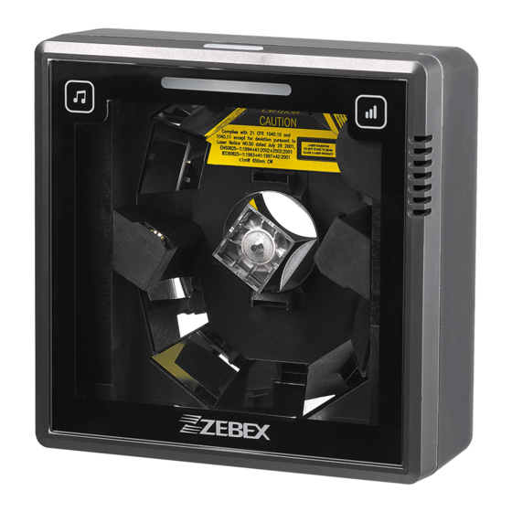
Page 10: Caution Label
Caution Label Figure 3: Label Cable Installation The scanner is to be connected to a host (e.g. POS). The use of external power is determined by your host but it is usually recommended. The scanner also supports an auxiliary scanner and EAS application. The figure below gives you an overview of the cable installation. -
Page 11: Connection
Connection Power The scanner requires a minimum of 450mA at 9 V DC power. The interface cable that comes with the scanner supports both direct power (where the scanner takes power from the host machine) and external power (that's what the supplied power adapter is for). -
Page 12: Connecting Auxiliary Scanner
Connecting Auxiliary Scanner To connect an auxiliary scanner to the AUX port: 1. Connect the auxiliary interface cable to the auxiliary port of the scanner. 2. Connect the other end of the cable to the auxiliary scanner. 3. Connect the power supply if necessary. 4. - Page 13 Figure 6: Host Cable Connection 3. Insert the bracket on interface cable to the cable release hole of the mounting plate as shown. Make sure the flat side of the bracket goes in first Figure 7: Cable Holder 4. Insert the latches of the mounting plate into the latch holes of the scanner. Figure 8: Latches 5.
-
Page 14: Interface Cable Replacement
Figure 9: Put the mounting plate back 6. Plug the other end of the cable to the host. 7. Plug the power adapter into the jack on the interface cable. 8. Plug the AC end of the power adapter into an AC outlet. The scanner powers up, the speaker sounds four beeps and the LED indicator glows blue. -
Page 15: Mounting
connector. When properly seated, the connector is secured in the scanner bottom by a flexible retention tab. The cable is designed to be field replaceable. Replacement cables can be obtained from your authorized distributor. To replace the cable, follow these steps. 1. -
Page 16: Diagrams For Mounting
Diagrams for Mounting The device is reserved with 2 mounting holes at the back and 4 mounting holes at bottom. Refer to the figure below for detailed information. Back View Unit: mm (inch) Figure 10: Diagrams for Mounting (Back) Bottom View Unit: mm (inch) Figure 11: Diagrams for Mounting (Bottom) -
Page 17: Mounting Plate Installation
Mounting Plate Installation 1. Position the mounting plate in the desired location and secure it in place. Figure 12: Mounting Hole Positions 2. Insert the interface cable in the cable release hole of the mounting plate. Figure 13: Position the interface cable 3. - Page 18 4. Move the scanner into position on the mounting plate, engaging the tab on the underside. Be careful not to pinch the cable. Figure 14: Slide the mounting plate into scanner...
-
Page 19: Auxiliary Handheld Scanner Connection (Optional)
Auxiliary Handheld Scanner Connection (Optional) The scanner supports the operation of an auxiliary handheld scanner, which may be connected via a 10-pin modular plug to the connector marked “AUX” at the back of the scanner. 1. Insert the 10-pin modular plug of scanner cable into the “Host” connector at the back of the scanner until a firm click is heard. -
Page 20: Back Mounting
5. Slide the mounting plate into the scanner. Be careful not to pinch any cables. Figure 17: Cable installation completed Back Mounting If desired, the scanner may be mounted to your own custom bracket by using the threaded mounting holes at the back (See Figure 1). The mounting holes readed to accommodate M3 x 0.5 machine screws to a depth of 6.0 mm. -
Page 21: Site Preparation
Site Preparation Configuring the Scanner In certain cases no setup is required. The scanner is either pre-programmed to sui the situation, or it automatically detects and is ready to go. In other cases the scanner must be informed about what kind of system it is connected to. This c e done in a few mom ents using the programming barcodes in the separate Programming Guide. -
Page 22: Set Up
Set Up 1. When the scanner is powered on (blue LED lights), find the <Enter/Exit Programming Mode> barcode in the Programming Guide and present this barcode to the scanner. When the scanner gives two beeps (one low and one high) and the LED turns red, it means the scanner is in programming mode. -
Page 23: Controlling The Scanner From Pos System
Controlling the Scanner from POS System he scanner can be controlled from the POS system via the RS-232C interface. trolling can be accompl ished by tra nsmitting the f ollowing single byte mmands to the scanner. The default setting of the commands are as follo ASCII Code Function... - Page 24 When disabled (default), the EAS tag is de-activated independently of any barcode scanning. Setting EAS Active Use this setting to set the polarity of the EAS allowing the scanner to send an EAS output after a good barcode read to deactivate a tag on the product. Setting EAS Timeout Use this setting to set EAS Timeout.
-
Page 25: Operation
7. Operation 7.1 LED Indications There are red and blue dual color LED indications on the head of the device indicating the operational status of the scanner. LED Status Indication LED off No power supplied to the scanner. Steady blue light The scanner is powered on and ready to scan. -
Page 26: Tone And Volume Adjustment
7.3 Tone and Volume Adjustment The scanner can be programmed with the Programming Guide to change beeper tone, volume and duration; the tone and volume can also be changed by using the touch control sensors in the front. Touch Control Sensor Tone Volume There are three tones to choose from. -
Page 27: Sleep Mode
7.4 Sleep Mode After the scanner has been inactive for a specific length of time, the laser and the motor would automatically turn off and the scanner would enter the sleep mode. The blue LED would blink as indication. It takes 2 steps to enter the sleep mode. The first step is the laser switching off after 10 minutes;... -
Page 28: How To Scan
8. How to Scan 8.1 Scan Volume The device is an omnidirectional presentation scanner with a 10-direction scan field with a 40-line scan pattern. The scan volume extends approximately 20cm (8”) in front of the scan window. Barcode labels can be easily read when presented towards the scanning window. -
Page 29: Scanning Mode
8.2 Scanning Mode The scanner can read barcodes in either sweep or presentation mode to accommodate different requirements. Sweep Mode means moving items through the scan volume. Left to right, right to left, top to bottom, bottom to top, etc. are all okay. Sweep Mode is usually used for high throughput and reduced product handling. -
Page 30: Maintaining The Scanner
9. Maintaining the Scanner The scanner is designed for long-term trouble-free operation and rarely requires any maintenance. Only an occasional cleaning of the scanner window is necessary in order to remove dirt and fingerprints. It can be cleaned while the scanner is running. -
Page 31: Trouble Shooting
10. Trouble Shooting This section contains information about how to solve problems that you may encounter when operating the scanner. However, before referring to the tips, make sure that the scanner is installed as instructed in this manual and that all cables are properly connected. -
Page 32: Specification
11. Specification Operational Light Source 650nm visible laser diodes (VLD) 32 bit Depth of Scan Field 0 – 200 mm (UPC/EAN 100%, PCS=90%) Scan Pattern 10 directions of scan field Scan Rate 3600 scans per second (omnidirectional) Number Scan Lines Minimum Bar Width 5mil @ PCS 90% Print Contrast... -
Page 33: Dimension
12. Dimension Unit: mm(inch) -
Page 34: Decode Zone
13. Decode Zone... -
Page 35: Pin Assignment Device
14. Pin Assignment 14.1 Device Host Port Auxiliary Port Host Function RS-232 IN Only Keyboard RS-232C Function Wedge RX_TTL N.C. N.C. N.C. Power +5V output, 300mA max. RTS_R KB_CLK Ground PC_CLK RTS_TTL N.C. TX_R Ground RX_R N.C. TX_TTL N.C. N.C. RX_TTL N.C. -
Page 36: Interface Cable
14.2 Interface Cable Keyboard Wedge Cable (for PS/2) PIN-OUT CONFIGURATION P1- MINI DIN (M) P2- MINI DIN (F) FUNCTION FUNCTION PC Data KB Data N.C. N.C. PC Clock KB Clock N.C. N.C. RS-232C Cable – DTE Pin Out DB-9 (F) FUNCTION RS-232C Cable –...
Need help?
Do you have a question about the Z-6182 and is the answer not in the manual?
Questions and answers