Table of Contents
Advertisement
Advertisement
Table of Contents

Subscribe to Our Youtube Channel
Related Manuals for Zebex Z-3192BT


Summary of Contents for Zebex Z-3192BT
- Page 1 Wireless Handheld Gun Type 2D Image Reader...
- Page 2 ’ ANUAL Revision History Changes to the original manual are listed below: Version Date Description of Version 2012/11/01 Initial release Wireless Handheld Gun Type 2D Image Reader...
-
Page 3: General Handling Precautions
’ ANUAL Important Notice No warranty of any kind is made in regard to this material, including, but not limited to, implied warranties of merchantability or fitness for any particular purpose. We are not liable for any errors contained herein nor for incidental or consequential damages in connection with furnishing, performance or use of this material. -
Page 4: For Ce-Countries
’ ANUAL Radio Notice This equipment generates uses and can radiate radio frequency energy. If not installed and used in accordance with the instructions in this manual, it may cause interference to radio communications. The equipment has been tested and found to comply with the limits for a Class A computing device pursuant to EN55022 and 47 CFR, Part 2 and Part 15 of the FCC rules. -
Page 5: Wireless Communication
’ ANUAL Wireless Communication Wireless technology operates 100M / 75M with communication cradle. Maximum communication range may vary depending on obstacles (person, metal, wall, etc.) or electromagnetic environment. The following conditions may affect the sensitivity of wireless communication. „ There is an obstacle such as a person, metal, or wall between this unit and wireless device. „... - Page 6 ’ ANUAL Bad host placement Good host placement At least 1 m 2. Move the access point (host/cradle) off the floor and away from walls and metal objects (such as metal file cabinets). Metal objects, walls, and floors will interfere with your wireless signals. The closer your access point is to these obstructions, the more severe the interference, and the weaker your connection will be.
-
Page 7: Table Of Contents
’ ANUAL Table of Contents Important Notice........................ii General Handling Precautions................ii Guidance for Printing ...................ii For CE-Countries....................iii Power Supply ......................iii Wireless Communication ..................iv Introduction .........................1 Product Overview ......................2 Scanner ........................2 Cradle ........................2 Scanner and Accessories....................3 Battery Installation.......................4 Installing Cable Clip ......................5 Connecting the Cradle....................6 Connecting the Cradle....................7 Charging the Battery ....................8... -
Page 8: Introduction
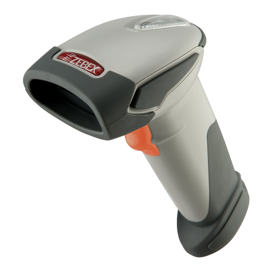
’ ANUAL Introduction This scanner is a gun type rugged wireless 2D image reader with a state of the art image sensor. Featuring a superb scanning ability and able to withstand 1.5 meter drop, it is ideal for manufacturing and logistic sectors. The cradle, a dongle, or devices with wireless technology can be the host of this scanner. -
Page 9: Product Overview
’ ANUAL Product Overview Scanner LED Indicator Exit Window Buzzer Trigger Strap Hole Metal Charging Contacts Cable Connector Cradle Charging Contacts Function Trigger/LED indicator Host Connector DC Power Connector Bluetooth Address Label Wireless Handheld Gun Type 2D Image Reader... -
Page 10: Scanner And Accessories
’ ANUAL Scanner and Accessories The scanner package contains: Wireless scanner with battery / Scanner cradle (optional) (without cradle) (with cradle) Li-ion battery pack Communication cable for cradle (optional) Mini USB B to mini USB A cable 5V USB Power adapter CD-ROM or handbook (Containing manual and programming guide) Cable clip... -
Page 11: Battery Installation
’ ANUAL Battery Installation Installing Batteries The rechargeable batteries are packed individually for shipping safety. Please follow the steps below to install the batteries. Always use the rechargeable batteries provided by the manufacturer to avoid any non-compatible danger or void the warranty. Unscrew the cap from the battery compartment at the bottom of the scanner and insert the battery. -
Page 12: Installing Cable Clip
’ ANUAL Installing Cable Clip Cable clip is used to hold the mini USB cable in USB Online Mode. With the cable clip, you can easily transform your wireless scanner into a wired one. Attaching Cable Clip Insert the cable clip to the strap hole as shown. Gently turn the cable clip counter-clockwise and push the cable clip all the way through the strap hole. - Page 13 ’ ANUAL Removing Cable Clip Detach the cable from the clip and detach the bottom part of the cable clip from the scanner handle. Unhook the left part of the cable clip from the strap hole then turn it clockwise. While in turning motion, push the cable clip all the way through.
-
Page 14: Connecting The Cradle
’ ANUAL Connecting the Cradle The cradle host features wireless technology and is designed to support radio communication to the scanner. It can be used for both battery charging and radio communication. Take the desirable interface cable and insert the RJ-45 connector on the bottom of the cradle. -
Page 15: Charging The Battery
’ ANUAL Charging the Battery The scanner offers two different ways to charge the battery: USB Cable or Cradle. To charge the battery using the cradle: Connect the cradle. Please see Connecting the Cradle section for more details. Place the scanner on the cradle. You will hear a short beep sound from the scanner indicating scanner is in contact with the cradle. -
Page 16: Power On The Scanner
’ ANUAL Approx. charging time: 5~6 hours The scanner will power on automatically when charging. Batteries shipped may not be full charged and should be fully charged for maximum charge capacity. Recommended charging environment is temperature in 0 C~35 C (32 F~95 F). -
Page 17: How To Scan
’ ANUAL How to Scan There are two ways to scan with this device. Handheld scanning Presentation scanning Handheld scanning Power on the scanner. Press the trigger and aim at the barcode as illustrated. When decoding is successful, the scanner beeps and the LED indicates blue. Presentation Scanning Put the scanner into the cradle for presentation scanning. -
Page 18: Radio Communication Host Type
’ ANUAL Radio Communication Host Type This scanner support three radio communication types: Cradle Host mode SPP master/slave mode HID mode Cradle Host Mode The scanner communicates with the host through the cradle and the cradle communicates directly to the host via host interface cable connection. Typically, scanner and cradle in the same delivery box are paired in factory. -
Page 19: Paging The Scanner
’ ANUAL Paging the Scanner Ensure the cradle is properly connected to the host and LED indicator is showing steady blue. Press the function trigger on the cradle. You should hear the scanner make 3 beep sounds and blue LED flash 3 times if it is in range. Scanner USB online to Host The scanner provides other ways for you to connect to the host. -
Page 20: Visible Indicators
’ ANUAL Visible Indicators Scanner There are 2 groups of LED indicators on top of the scanner. These indicate the operational status of the scanner. Group 2 Group 1 LED Status Indication Group_ 2 Group_1 Blue Flashing Waiting for radio connection (flash time 0.5s : 0.5s). -
Page 21: Cradle
’ ANUAL Cradle Cradle LED LED Status Indication Red steady and blue Cradle is radio disconnected and power from DC continuous flashing adaptor is lost. Cradle is radio connected. But lost DC power from the Steady red and blue adaptor. Red and blue USB Interface communication failed. -
Page 22: Ack/Nak Protocol Or Frame Packing
’ ANUAL ACK/NAK Protocol or Frame Packing When scanner is in SPP Master/Slave mode, and add in the data protocol or packing could confirm the data reliability. Refer to below for different setting options: a) No ACK/NAK protocol: data Remote BT BT Scanner device b) ACK/NAK only... -
Page 23: Scanner To Remote Application
’ ANUAL Scanner to Remote Application Data Format of Packet To send a data (barcode) to the remote application, the BT scanner has to encapsulate it: Size of Data Barcode Reserved (Format Data (End of (Header) payload Type Byte Byte) Byte) 1 byte 1 byte... - Page 24 ’ ANUAL Barcode Type Table Code Value Code39 0x11 Codabar 0x01 Code128 0x03 Interleaved 2/5 0x02 Code93 0x06 UPC-E 0x14 UPC-A 0x24 EAN-8 0x34 EAN-13 0x44 Chinese Post Code 0x05 0x07 Wireless Handheld Gun Type 2D Image Reader...
-
Page 25: Pin-Out Configuration
’ ANUAL Pin-out Configuration Scanner mini USB Pin-Out Configuration PIN 1. PIN 2. USB_D- PIN 3. USB_D+ PIN 4. PIN 5. Cradle Phone Jack Pin-Out Configuration RJ 1. RTS_EIA RJ 6. RX_ EIA RJ 2. KB Data / USB_D+ RJ 7. KB Clock RJ 3. -
Page 26: Cable Pin-Out
’ ANUAL Cable Pin-out Keyboard Wedge Cable (for PS/2) PIN-OUT CONFIGURATION MINI DIN (M) MINI DIN(F) FUNCTION FUNCTION PC Data KB Data N.C. N.C. PC Clock KB Clock N.C. N.C. RS-232 Cable (DTE pin out) PIN-OUT CONFIGURATION DB-9 (F) FUNCTION RS-232 Cable (DCE pin out) PIN-OUT CONFIGURATION DB-9 (F) -
Page 27: Programming Guide
’ ANUAL Programming Guide Program Procedure Using Barcode Manual Power up the scanner. Scan the Start of Configuration barcode. Scan the barcode for the desired feature. Multiple features can be enabled/disabled before scanning the End of Configuration barcode. Scan the End of Configuration barcode and save the new configuration. To give up a configuration change, power off the scanner before scanning the End of Configuration barcode or scan the Abort barcode. -
Page 28: Default Parameters
’ ANUAL Default Parameters The factory default setting table gives the default settings of all the programmable parameters. The default settings will be restored whenever the "Reset" programming label is scanned and the scanner is in programming mode. Default values are highlighted in grey background in the settings. - Page 29 Enable Header and trailer None Inter-message delay None Inter-character delay None Code Identifiers Default Identifier code as ZEBEX Disable standard Identifier code as AIM Disable standard Code 39 identifier code ITF 2 of 5 identifier code Chinese post code identifier...
- Page 30 ’ ANUAL MSI identifier code Code 11 identifier code Standard 2 of 5 identifier code Industrial 2 of 5 identifier code GS1 DataBar identifier code GS1 DataBar Limited identifier code GS1 DataBar Expanded identifier code Default Data Transmit Format Code Message format EAN-13 D1 D2 D3 D4 D5 D6 D7 D8 D9 D10 D11 D12 D13...
-
Page 31: Connecting To A Host
’ ANUAL Connecting to a Host The scanner provides several data transmit methods to communicate with the host. User may select the method according to their preferences. Read this section to learn the setups for connecting to different hosts. Start Of Configuration USB Online Mode The scanner connects directly to a USB host to recharge and transmit data. -
Page 32: Cradle Host Mode
’ ANUAL Start Of Configuration Cradle Host Mode The scanner communicates with the host through the cradle. Typically, scanner and cradle in the same delivery box are paired and corresponded to host interface in factory. To check if the scanner is paired to the cradle, check the scanner LED group1 for slow blue flash and check the top cradle LED for steady blue light. -
Page 33: Wireless Mode
’ ANUAL Start Of Configuration Wireless Mode The scanner connects to the host via wireless connection. You may select SPP Master or SPP Slave for PC connection or select HID mode and Smart phone mode for smart phone connection. SPP Slave Mode In this mode, the scanner connects to the host /PC via wireless connection and performs like there’s a serial connection. - Page 34 ’ ANUAL Start Of Configuration SPP Master Mode In this mode, the scanner connects to the host /PC via wireless connection and performs like there’s a serial connection. In master mode, the scanner initiates the connection to the remote device Power on of the remote device and have its address ready in hand and make it discoverable.
- Page 35 ’ ANUAL Start Of Configuration BT HID mode In BT HID mode, the scanner connects to the host /PC via wireless connection and performs like there’s a keyboard connection. The scanner initiates the connection to the remote device Power on the scanner and program it with “BT HID Mode”. To connect a smart mobile phone (for example, iPhone, Android), the Smart phone mode must also be enabled.
- Page 36 ’ ANUAL Start Of Configuration Setting Pin Code To change the pin code, use the “Set pin code” setting. Default is “12345678”. Use the ASCII table in Programming Guide to input the new code (must be at least 4 digits and not more than 8 numeric digits). Scan “Save Setting”...
- Page 37 ’ ANUAL Start Of Configuration Setting Name To change the name displayed when the scanner is discovered, scan the “Friendly device name set” label. Default name is “ZBBT”. Use the ASCII table in Programming Guide to input the name (Max.12 digits). Scan “Confirm Setting”...
-
Page 38: Data Transnit Method
’ ANUAL Start Of Configuration Data Transnit Method The data transfer method includes three types: Normal (default), Out-of-Range Mode, and Batch Mode. Users may modify this setting according to their preferences. Normal When the scanner is within the connection range, the scanned data will be transferred to the host computer immediately. - Page 39 ’ ANUAL Start Of Configuration Batch Mode Whether within the connection range or not, in batch mode, the scanner stores all scanned data that will be transferred to the host computer after scanning “Send Batch Data” label. Number of storable bar codes = 61,365 bytes of memory / (number of characters in the bar code +2) Note: Scanner LED indicator will not flash while waiting for connection in this mode...
- Page 40 ’ ANUAL Start Of Configuration Batch Transfer Use the settings in this section to setup batch transfer. Scanning this label automatically exits you from the Programming Mode. Press and hold the trigger for over Send Batch Data By 1 second to send the data Scanning Label Data is ready to be transferred upon USB connection.
-
Page 41: System Function Settings
’ ANUAL System Function Settings Default values are highlighted in grey background. Start Of Configuration Barcode Value Description Return scanner to factory defaults Return cradle host to factory defaults Return to USB default (Communication cradle link required) Return to wand emulation default (Communication cradle link required) Return to RS232 default (Communication cradle link required) - Page 42 ’ ANUAL Start Of Configuration Barcode Value Description Display firmware version Abort (exit programming mode without any updates) Scan Mode Trigger mode The scanner becomes inactive as soon as the data is transmitted. It must be triggered to become active again Auto scan mode The scanner is still active after the data is transmitted but the successive transmission of the same barcode is not...
- Page 43 ’ ANUAL Start Of Configuration Radio Communication Setting Cradle Host mode Cradle Host mode enable Enable cradle mode with this setup Unlock pairing mode In this mode, the scanner can pair with another cradle when disconnected Lock pairing mode. In this mode, the scanner can not pair with another cradle Undo pairing Undo the pairing between the cradle and the scanner...
- Page 44 ’ ANUAL Start Of Configuration USB Online mode USB online scan disable USB online scan enable USB online scan, Ignore radio communication BT HID mode BT HID mode (Combo keyboard) For Apple mode (Must execute BT HID mode first) SPP Master/Slave mode Scanner SPP Master enable SPP Master (Connect wireless address “BxxxxxxxxxxxxT”...
- Page 45 ’ ANUAL Start Of Configuration Default Device name Friendly device name set Delete pin code Confirm Setting (for address, device name, and pin code setting required) Required Pair with slave (SPP Master) Discover enable Discover disable Encryption enable Encryption disable Data communication without protocol Data communication with ACK/NAK protocol Data communication with Packing protocol...
- Page 46 ’ ANUAL Start Of Configuration Data Transmit Mode Data transmit normal Out of range buffer enable Batch mode Send Batch Data By Scanning Label Clear batch data after send Clear batch data by scanning “Delete batch data” label Delete batch data Send Batch Data on line USB cable contact.
- Page 47 ’ ANUAL Start Of Configuration Radio protocol communication parameter Radio protocol timeout= 3 sec Radio protocol timeout= 5 sec Radio protocol timeout =8 sec Radio protocol timeout= 10 sec Radio protocol timeout =13 sec Radio protocol timeout =16 sec Radio protocol timeout= 20 sec End Of Configuration Wireless Handheld Gun Type 2D Image Reader...
- Page 48 ’ ANUAL Start Of Configuration Power off timeout parameter Power off timeout=5 min Power off timeout=10 min Power off timeout=20 min Power off timeout=30 min Power off timeout=1 hr Power Off timeout : 2 hr Power Off timeout : 4 hr Power Off timeout : 6 hr Power Off timeout : 8 hr End Of Configuration...
- Page 49 ’ ANUAL Start Of Configuration Power Always On Power off by scanning this label Link beeper enable Link beeper disable Power-up beeper enable Power-up beeper disable Same Code Delay 50 msec 100 msec 200 msec 300 msec End Of Configuration Wireless Handheld Gun Type 2D Image Reader...
- Page 50 ’ ANUAL Start Of Configuration 400 msec 500 msec 600 msec 700 msec 800 msec 1000 msec Infinite End Of Configuration Wireless Handheld Gun Type 2D Image Reader...
- Page 51 ’ ANUAL Start Of Configuration Operation Function Setting Good Read Beeper Tone Selection Medium beeper tone High beeper tone Low beeper tone Speaker disable End Of Configuration Wireless Handheld Gun Type 2D Image Reader...
- Page 52 ’ ANUAL Start Of Configuration Beeper Duration Selection Long Medium Short Ultra Short Ultra Long End Of Configuration Wireless Handheld Gun Type 2D Image Reader...
- Page 53 ’ ANUAL Start Of Configuration Vibration Parameter (Optional function, available only for customers of special request ) Good read vibrator enable Good read vibrator disable Good read beeper and vibrator enable Vibration duration=100msec Vibration duration=200msec Vibration duration=300msec Vibration duration=400msec Vibration duration=500msec Vibration duration=1 second Vibration duration=2 second Vibration duration=3 second...
- Page 54 ’ ANUAL Start Of Configuration Inter Character Delay 0 ms 2 ms 5 ms 10 ms 20 ms 50 ms Inter Message Delay 0 ms 100 ms 500 ms 1000 ms End Of Configuration Wireless Handheld Gun Type 2D Image Reader...
- Page 55 ’ ANUAL Start Of Configuration Interface Settings RS-232C Interface Setting Baud Rate 115200 19200 9600 4800 2400 1200 Parity Bit Even parity Odd parity Mark parity Space parity None parity Stop Bit 1 stop bit 2 stop bit Data Bit 7 data bit 8 data bit End Of Configuration...
- Page 56 ’ ANUAL Start Of Configuration Handshaking Protocol None handshaking ACK/NAK Xon/Xoff RTS/CTS Enable BEEPER ON<BEL> CHARACTER Ignore Beep on<BEL> character ACK/NAK response time 300ms ACK/NAK response time 2 sec ACK/NAK response time 500 ms ACK/NAK response time 3 sec ACK/NAK response time 1 sec ACK/NAK response time 5 sec ACK/NAK response time infinity End Of Configuration...
- Page 57 ’ ANUAL Start Of Configuration Message Terminator RS-232 message terminator—none RS-232 message terminator—CR/LF RS-232 message terminator—CR RS-232 message terminator—LF RS-232 message terminator—H tab RS-232 message terminator—STX/ETX RS-232 message terminator—EOT End Of Configuration Wireless Handheld Gun Type 2D Image Reader...
- Page 58 ’ ANUAL Start Of Configuration Keyboard Wedge Setting Keyboard Wedge Setting IBM PC/AT/PS/2 Keyboard emulation International Keyboard mode ( ALT method) Keyboard language support---USA Keyboard language support---UK send scan code Keyboard language support---GERMANY Keyboard language support---FRENCH send scan code Keyboard language support---SPANISH send scan code Keyboard language support---ITALIAN send scan code...
- Page 59 ’ ANUAL Start Of Configuration Message Terminator Keyboard terminator---none Keyboard terminator---Enter Keyboard terminator---H-TAB End Of Configuration Wireless Handheld Gun Type 2D Image Reader...
- Page 60 ’ ANUAL Start Of Configuration USB Interface Setting USB interface International Keyboard mode ( ALT method) Keyboard language support---USA Keyboard language support---GERMANY Keyboard language support---FRENCH send scan code Keyboard language support---SPANISH send scan code Keyboard language support---JAPANESE Keyboard language support---ITALIAN Message Terminator Keyboard terminator---none Keyboard terminator---Enter...
- Page 61 ’ ANUAL Start Of Configuration Wand Emulation Setting Wand emulation is not supported as standard, if needed, please contact your distributor. (Code128, Code93 not supported) Wand Emulation All barcode will be decoded and transmitted in that symbology Enable Wand output data format as CODE39 Wand emulation data output black=high Scan this bar code to set quiet zones and spaces low and bars =high...
- Page 62 ’ ANUAL Start Of Configuration Wand Emulation (Cont’d) Wand emulation speed-----Low This option allows the transmission of wand emulation at 1ms narrow element width Wand emulation speed-----medium This option allows the transmission of wand emulation at 600us narrow element width Wand emulation speed-----high This option allows the transmission of wand emulation at 300us narrow element width...
- Page 63 ’ ANUAL Start Of Configuration Smart Phone Software Keypad Control Setting Smart Phone Software Keypad Control Multi-media keyboard mode This option enables Multi-media keyboard mode Software keypad enable/disable This option enable or disable Software keypad To enable/disable Software keyboard: Scan the Start Of Configuration barcode. Scan the Multi-media keyboard mode barcode.
- Page 64 ’ ANUAL Start Of Configuration The Symbologies Codabar Parameter Setting Barcode Barcode Label Description Value RC02 Codabar enable RD02 Codabar disable CB05 Codabar start/stop character transmission none CB06 Codabar start/stop character transmission A,B,C,D CB07 Codabar start/stop character transmission DC1~DC4 CB08 Codabar start/stop character transmission a/t,b/n,c/*,d/e CB09...
- Page 65 ’ ANUAL Start Of Configuration Barcode Barcode Label Description Value CB13 No check character CB14 Validate modulo 16,but don’t transmit CB15 Validate modulo 16 and transmit CB18 Codabar CLSI Editing enable When enabled, this parameter strips the start and stop characters and inserts a space after the first, fifth, and tenth characters of a 14-character Codabar symbol.
- Page 66 ’ ANUAL Start Of Configuration Code 39 Parameter Setting Barcode Barcode Label Description Value RC01 Code 39 enable RD01 Code 39 disable RC13 Code 32 enable RD13 Code 32 disable DC00 Code 39 data redundant check=off DC01 Code 39 data redundant check=1 DC02 Code 39 data redundant check=2 DC03...
- Page 67 ’ ANUAL Start Of Configuration Barcode Barcode Label Description Value 3901 Standard code 39 3902 Full ASCII code 39 3903 Code 39 start/stop character transmission 3904 Code 39 start/stop character without transmission 3905 Code 39 check digit calculate and transmit 3906 Code 39 check digit calculate but without transmit 3907...
- Page 68 ’ ANUAL Start Of Configuration Code 93 Parameter Setting Barcode Barcode Label Description Value RC08 Code 93 enable RD08 Code 93 disable DC30 Code 93 data redundant check=off DC31 Code 93 data redundant check=1 DC32 Code 93 data redundant check=2 DC33 Code 93 data redundant check=3 9301...
- Page 69 ’ ANUAL Start Of Configuration Code 128 Parameter Setting Barcode Barcode Label Description Value RC06 Code 128 enable RD06 Code 128 disable RC10 EAN-128 enable RD10 EAN-128 disable DC40 Code 128 data redundant check=off RC31 ISBT-128 enable RD31 ISBT-128 disable DC41 Code 128 data redundant check=1 DC42...
- Page 70 ’ ANUAL Start Of Configuration Chinese Post Code Parameter Setting Barcode Barcode Label Description Value RC05 Chinese post code enable RD05 Chinese post code disable DC60 Chinese post code data redundant check=off DC61 Chinese post code data redundant check=1 DC62 Chinese post code data redundant check=2 DC63 Chinese post code data redundant check=3...
- Page 71 ’ ANUAL Start Of Configuration MSI/Plessy Parameter Setting Barcode Barcode Label Description Value RC14 MSI enable RD14 MSI disable DC70 MSI data redundant check= off DC71 MSI data redundant check=1 DC72 MSI data redundant check=2 DC73 MSI data redundant check=3 MS01 MSI/Plessy maximum length setting MS02...
- Page 72 ’ ANUAL Start Of Configuration Barcode Barcode Label Description Value MS11 MSI Check Digit Algorithm (Mod10/Mod10) Two algorithms are possible for the verification of the second MSI check digit. Select the barcode corresponding to the algorithm used to encode the check digit MS12 MSI Check Digit Algorithm (Mod10/Mod11) End Of Configuration...
- Page 73 ’ ANUAL Start Of Configuration Code 11 Interface Setting Barcode Barcode Label Description Value RC07 Code 11 enable RD07 Code 11 disable 1101 Code 11 maximum length setting 1102 Code 11 minimum length setting Confirm to save this setting (required for reading full ASCII table and length setting) 1103 Code 11 one check digit verification...
- Page 74 ’ ANUAL Start Of Configuration ITF 2 of 5 Parameter Setting Barcode Barcode Label Description Value RC04 ITF 2 of 5 enable RD04 ITF 2 of 5 disable RC09 IATA code enable RD09 IATA disable RC32 Convert ITF 2 of 5 to EAN-13 enable RD32 Convert ITF 2 of 5 to EAN-13 disable DC80...
- Page 75 ’ ANUAL Start Of Configuration Barcode Barcode Label Description Value IT01 ITF 2 of 5 code maximum length setting IT02 ITF 2 of 5 code minimum length setting IT06 ITF 2 of 5 one fixed length setting IT07 ITF 2 of 5 two fixed length setting Confirm to save this setting (required for reading full ASCII table and length setting) IT08...
- Page 76 ’ ANUAL Start Of Configuration Standard 2 of 5 Parameter Setting Barcode Barcode Label Description Value RC22 Standard 2 of 5 code enable RD22 Standard 2 of 5 code disable D051 Standard 2 of 5 code maximum length setting D052 Standard 2 of 5 code minimum length setting Confirm to save this setting (required for reading full ASCII table and length setting)
- Page 77 ’ ANUAL Start Of Configuration Industrial 2 of 5 Parameter Setting Barcode Barcode Label Description Value RC21 Industrial 2 of 5 code enable RD21 Industrial 2 of 5 code disable D251 Industrial 2 of 5 code maximum length setting D252 Industrial 2 of 5 code minimum length setting Confirm to save this setting (required for reading full ASCII table and length setting)
- Page 78 ’ ANUAL Start Of Configuration UPC/EAN/JAN Parameter Setting Barcode Barcode Label Description Value RC11 EAN convert to ISSN/ISBN enable RD11 EAN convert to ISSN/ISBN disable RC03 UPC/EAN/JAN enable RD03 UPC/EAN/JAN disable UE01 UPC/EAN/JAN all enable UE02 EAN-8 or EAN-13 enable UE03 UPC-A and EAN-13 enable UE04...
- Page 79 ’ ANUAL Start Of Configuration Barcode Barcode Label Description Value UE10 Add on 5 only UE11 Add on 2 only UE12 Add on 2 or 5 UE13 Force UPC-E to UPC-A format enable UE14 Force UPC-E to UPC-A format disable UE15 Force UPC-A to EAN-13 format enable UE16...
- Page 80 ’ ANUAL Start Of Configuration Barcode Barcode Label Description Value UE23 Transmit EAN-8 check digit enable UE24 Transmit EAN-8 check digit disable UE25 Transmit EAN-13 check digit enable UE26 Transmit EAN-13 check digit disable UE27 Transmit UPC-A leading character enable UE28 Transmit UPC-A leading character disable UE30...
- Page 81 ’ ANUAL Start Of Configuration Barcode Barcode Label Description Value DC12 UPC-A data redundant check=2 DC13 UPC-A data redundant check=3 DC14 UPC-E data redundant check=off DC15 UPC-E data redundant check=1 DC16 UPC-E data redundant check=2 DC17 UPC-E data redundant check=3 DC20 EAN-13 data redundant check=off DC21...
- Page 82 ’ ANUAL Start Of Configuration Barcode Barcode Label Description Value UE35 EAN/UPC +add-on mandatory for 978/977 bookland (Supplement requirement, not sent for other) UE38 EAN/UPC +addon mandatory for 978/977 bookland (Supplement requirement, optional for other) UE42 EAN/UPC +addon mandatory for 491 Japanese bookland (Supplement requirement, not sent for other) UE43...
- Page 83 ’ ANUAL Start Of Configuration Barcode Barcode Label Description Value RC33 UPCE1 enable RD33 UPCE1 disable UE68 UPCE1 Check Digit Transmit enable UE69 UPCE1 Check Digit Transmit disable UE70 UPCE1 Preamble off UE71 UPCE1 Preamble System Character UE72 System Character & Country Code UE73 Convert UPCE1 to UPCA enable UE74...
- Page 84 ’ ANUAL Start Of Configuration Telepen Parameter Setting Barcode Barcode Label Description Value RC25 Telepen enable RD25 Telepen disable TE03 Telepen numeric mode enable TE04 AIM Telepen enable End Of Configuration Wireless Handheld Gun Type 2D Image Reader...
- Page 85 ’ ANUAL Start Of Configuration Matrix 2 of 5 Parameter Setting Barcode Barcode Label Description Value RC12 Matrix 2 of 5 enable RD12 Matrix 2 of 5 disable D151 Matrix 2 of 5 maximum length setting D152 Matrix 2 of 5 minimum length setting Confirm to save this setting (required for reading full ASCII table and length setting) D153...
- Page 86 ’ ANUAL Start Of Configuration GS1 DataBar Parameter Setting There are 7 kinds of barcodes in the GS1 DataBar family and they are categorized into three groups. Barcode types in the same group use the same barcodes for setting. Group Representative Contents Group 1...
- Page 87 ’ ANUAL Start Of Configuration GS1 DataBar Limited (Formally RSS Limited) Barcode Barcode Label Description Value RC16 GS1 DataBar Limited enable RD16 GS1 DataBar Limited disable SS10 Transmit GS1 DataBar Limited check digit SS11 Don’t transmit GS1 DataBar Limited check digit SS12 Transmit GS1 DataBar limited application ID (01) SS13...
- Page 88 ’ ANUAL Start Of Configuration GS1 DataBar Expanded (Formally RSS Expanded) Barcode Barcode Label Description Value RC17 GS1 DataBar Expanded enable RD17 GS1 DataBar Expanded disable SS07 GS1 DataBar Expanded/EAN-128 emulation enable SS06 GS1 DataBar Expanded/EAN-128 emulation disable SS08 GS1 DataBar Expanded check digital enable SS09 GS1 DataBar Expanded check digital disable SS16...
- Page 89 ’ ANUAL Start Of Configuration Postal Codes Setting Barcode Barcode Label Description Value RC35 US Postnet enable RD35 US Postnet disable RC36 US Planet enable RD36 US Planet disable RC37 Transmit US Postal Check Digit enable RD37 Transmit US Postal Check Digit disable RC38 UK Postal enable RD38...
- Page 90 ’ ANUAL Start Of Configuration Barcode Barcode Label Description Value RC40 Japan Postal enable RD40 Japan Postal disable RC41 Australian Postal enable RD41 Australian Postal disable RC42 Dutch Postal enable RD42 Dutch Postal disable RC43 4State Postal enable RD43 4State Postal disable RC44 Post US4 enable RD44...
- Page 91 ’ ANUAL Start Of Configuration Composite Setting Barcode Barcode Label Description Value RC45 Composite cc-c enable RD45 Composite cc-c disable RC46 Composite cc-A/B enable RD46 Composite cc-A/B disable RC47 Composite TLC-39 enable RD47 Composite TLC-39 disable UC00 UPC Composite Mode never linked UC01 UPC Composite Mode always linked UC02...
- Page 92 ’ ANUAL Start Of Configuration 2D Setting Barcode Barcode Label Description Value RC48 PDF417 enable RD48 PDF417 disable RC49 MicroPDF417 enable RD49 MicroPDF417 disable RC50 Code128 Emulation enable RD50 Code128 Emulation disable RC51 Data Matrix enable RD51 Data Matrix disable End Of Configuration Wireless Handheld Gun Type 2D Image Reader...
- Page 93 ’ ANUAL Start Of Configuration Barcode Barcode Label Description Value RC52 Maxicode enable RD52 Maxicode disable RC53 QR Code enable RD53 QR Code disable RC54 MicroQR enable RD54 MicroQR disable RC55 Aztec enable RD55 Aztec disable End Of Configuration Wireless Handheld Gun Type 2D Image Reader...
- Page 94 ’ ANUAL Start Of Configuration Symbology-Specific Security Levels Barcode Barcode Label Description Value SL00 Security Level 0 The decoder offers four levels of decode security for delta bar codes, which include the Code 128 family, UPC/EAN, and Code 93. Select increasing levels of security for decreasing levels of bar code quality SL01 Security Level 1...
- Page 95 ’ ANUAL Start Of Configuration MicroPDF Features Barcode Barcode Label Description Value MP03 Transmit MicroPDF Control Header enable When enabled, this activates transmission of the control header, which contains the segment index and the file ID, in Macro PDF symbols. For example, the field may be: \92800000\725\120\343. The five digits after the \928 are the segment index (or block index), and \725\120\343 is the file ID MP04...
- Page 96 ’ ANUAL Start Of Configuration Imager Preferences Barcode Barcode Label Description Value IP00 Decoding Autoexposure enable Select enable Decoding Autoexposure to allow the SE4500 to control gain settings and exposure (integration) time to best capture an image for decode mode IP01 Decoding Autoexposure disable IP02...
-
Page 97: Data Editing
’ ANUAL Start Of Configuration Data Editing Identifier Code Barcode Barcode Label Description Value IS00 Disable identifier code IS01 Enable identifier code table as factory standard IS03 Enable identifier code table as AIM standard. CI01 Code 39 identifier code setting CI02 ITF 2 of 5 identifier code setting CI03... - Page 98 ’ ANUAL Start Of Configuration Barcode Barcode Label Description Value CI08 Codabar identifier code setting CI09 Code 128 identifier code setting CI10 Code 93 identifier code setting CI11 MSI identifier code setting CI12 GS1 DataBar Omnidirectional identifier code setting CI13 GS1 DataBar Limited identifier code setting CI14 GS1 DataBar expanded identifier code setting...
- Page 99 ’ ANUAL Start Of Configuration Header and Trailer Barcode Barcode Label Description Value CP11 Add code length as header enable (2 digits) Add code length as header disable (2 digits) CP12 Header (Preamble) HT01 Trailer (Postamble) HT02 Truncate header character HT03 Truncate trailer character HT04...
-
Page 100: Full Ascii Code 39 Table
’ ANUAL Start Of Configuration Full ASCII Code 39 Table Hexa Hexa- Code 39 ASCII Code 39 ASCII code code Full ASCII ---NUL Full ASCII ---SI Function key-----“Shift” Full ASCII ---SOH Full ASCII ---DLE Function key-----“Ins” Function key----- “5(num)” Full ASCII ---STX Full ASCII ---DC1 Function key-----“Del”... - Page 101 ’ ANUAL Start Of Configuration Full ASCII Code 39 Table (continued) Hexa- Hexa- Code 39 ASCII Code 39 ASCII code code Full ASCII ---RS Full ASCII ---- Function key-----“CTL(L)” Full ASCII ---US Full ASCII ---. Function key-----“ALT(L)” Full ASCII ---SP Full ASCII ---/ Full ASCII ---! Full ASCII ---0...
- Page 102 ’ ANUAL Start Of Configuration Full ASCII Code 39 Table (continued) Hexa- Hexa- Code 39 ASCII Code 39 ASCII code code Full ASCII ---< Full ASCII ---K Full ASCII ---= Full ASCII ---L Full ASCII ---> Full ASCII ---M Full ASCII ---? Full ASCII ---N Full ASCII ---@ Full ASCII ---O...
- Page 103 ’ ANUAL Start Of Configuration Full ASCII Code 39 Table (continued) Hexa- Hexa- Code 39 ASCII Code 39 ASCII code code Full ASCII ---Z Full ASCII ---i Full ASCII ---[ Full ASCII ---j Full ASCII ---\ Full ASCII ---k Full ASCII ---] Full ASCII ---l Full ASCII ---^ Full ASCII ---m...
- Page 104 ’ ANUAL Start Of Configuration Full ASCII Code 39 Table (continued) Hexa- Hexa- Code 39 ASCII Code 39 ASCII code code Full ASCII ---x Full ASCII ---| Full ASCII ---y Full ASCII ---} Full ASCII ---z Full ASCII ---~ Full ASCII ---{ Full ASCII ---DEL End Of Configuration Wireless Handheld Gun Type 2D Image Reader...
-
Page 105: Appendix 1: Usb Virtual Com Driver Installation
’ ANUAL Appendix 1: USB Virtual COM Driver Installation Contact your distributor to get the driver and follow the steps below to enable USB virtual COM port. Connect the handheld scanner and the host (e.g. a PC) with a USB interface cable. Enable USB virtual COM port with programming barcode from System Function Settings. -
Page 106: Appendix 2: Barcode Length Setting
’ ANUAL Appendix 2: Barcode Length Setting Introduction The length of a barcode is the number of characters it contains, including check digits. As listed in the Default Parameters section, each barcode type has different default length. You may change the setting by the following procedure. To set up barcode length, the paramours to be determined are barcode type and the desired barcode length.
Need help?
Do you have a question about the Z-3192BT and is the answer not in the manual?
Questions and answers