Table of Contents
Advertisement
Quick Links
Copyright Notice
This document is copyrighted, 2002. All rights are reserved. The original
manufacturer reserves the right to make improvements to the products described
in this manual at any time without notice.
No part of this manual may be reproduced, copied, translated or transmitted in any
form or by any means without the prior written permission of the original
manufacturer. Information provided in this manual is intended to be accurate and
reliable. However, the original manufacturer assumes no responsibility for its use,
nor for any infringements upon the rights of third parties which may result from
its use.
Acknowledgments
PC-LabCard is a trademark of Advantech Co., Ltd. IBM and PC are trademarks of
International Business Machines Corporation. MS-DOS, Windows®, Microsoft
Visual C++ and Visual BASIC are trademarks of Microsoft
®
and Pentium
are trademarks of Intel Corporation. Delphi and C
trademarks of Inprise Corporation.
CE notification
The MIC-3620, developed by ADVANTECH CO., LTD., has passed the CE test
for environmental specifications when shielded cables are used for external
wiring. We recommend the use of shielded cables. This kind of cable is available
from Advantech. Please contact your local supplier for ordering information.
On-line Technical Support
For technical support and service, please visit our support website at:
http://www.advantech.com/support
®
Corporation. Intel
++
Part No.2003362000
Printed in Taiwan
®
®
Builder are
1st Edition
December 2002
Advertisement
Table of Contents

Related Manuals for Advantech MIC-3620


Summary of Contents for Advantech MIC-3620
- Page 1 Acknowledgments PC-LabCard is a trademark of Advantech Co., Ltd. IBM and PC are trademarks of ® International Business Machines Corporation. MS-DOS, Windows®, Microsoft ®...
-
Page 2: Table Of Contents
Contents INTRODUCTION..............................1 1.1 I ............................2 NTRODUCTION 1.2 F ..............................2 EATURES 1.3 S ............................3 PECIFICATIONS HARDWARE CONFIGURATION........................5 2.1 I ...........................6 NITIAL NSPECTION ........................7 ARDWARE NSTALLATION .........................9 OARD AYOUT IMENSIONS PIN ASSIGNMENT & WIRING........................11 3.1 P .............................12 IN ASSIGNMENTS REGISTER STRUCTURE & FORMAT...................... 15 ..........................16 EGISTER T RUCTURE... -
Page 3: Introduction
Introduction... -
Page 4: Ntroduction
1.1 Introduction The MIC-3620 is a 3U-sized 8-port High Speed RS-232 PCI Comm. CompactPCI™ and serial communication card, which complies with PICMG 2.0 R2.1 CompactPCI specifications. The MIC-3620 requires only one CPCI slot within the computer and provides independent serial channels. All channels are addressed in a continuous 32 byte I/O block for simplified software access. -
Page 5: Specifications
1.3 Specifications • Bus Interface: CPCI bus specification 2.1x compliant • IRQ: all ports use the same IRQ assigned by PCI Plug-and-Play • Data bits: 5, 6, 7, 8 • Stop bits: 1, 1.5, 2 • Parity: none, even, odd •... -
Page 7: Hardware Configuration
Hardware Configuration... -
Page 8: Initial Inspection
2.1 Initial Inspection In addition to this manual, you should find the following items inside the shipping package of the MIC-3620: • CPCI communication interface card MIC-3620 • Advantech Automation Software CD-ROM • CPCI communication card user's manual • Wiring cable Prior shipping, we have carefully inspected the CPCI communication card series. -
Page 9: Hardware Installation
Step 3: Hold the lower handle and pull the handle down to unlock it. Step 4: Insert the MIC-3620 card into the CPCI chassis carefully by sliding the lower edges of the card into the card guides. Step 5: Gently push the card into the slot by sliding the card along the card guide until J1 meets the long needle on the backplane. - Page 10 To remove a card: Step 1: Push the handle down to unlock the card, and the CPCI system will automatically uninstall the card configuration. Step 2: Once the system finishes the devic e configuration, the Blue LED on front plane will turn on. Now you can slide the card out. Note Because the card holds “Hot-Swap”, the above steps will remove the card process when the system is on.
-
Page 11: Board Layout: Dimensions
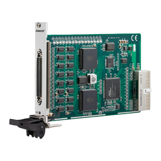
2.3 Board Layout: Dimensions Figure 1-1: MIC-3620 board layout: Dimensions Connectors MIC-3620 has a 68-pin SCSI connectors. -
Page 13: Pin Assignment & Wiring
Pin Assignment & Wiring... -
Page 14: Pin Assignments
3.1 Pin assignments The MIC-3620 has RS-232 8-ports. The following lists the pin assignments of the SCSI68 connector on the bracket. You may fabricate octopus cable for SCSI68 to 8 x DB9 with these output pin. Pin No. Signal Pin No. - Page 15 The following diagrams show the pin assignments for the MIC-3620 SCSI 68 pin connector. Figure 3-1: MIC-3620 RS232 Mode SCSI 68P Connector...
-
Page 17: Register Structure & Format
Register structure & format... -
Page 18: Register Structure
4.1 Register Structure This appendix gives short descriptions of each of the module's registers. For more information please refer to the data book for the OX16C954 UART chip. All registers are one byte. Bit 0 is the least significant bit, and bit 7 is the most significant bit. - Page 19 Else, while Bit7 of MCR is Logic”0”, TCR=0x00, set the divisor as follows: Baudrate Divisor 230400 307200 460800 921600 Table 4-2 BASE+1 Interrupt Enable Register (IER) when DLAB=0 Bit0 Enable received-data-available interrupt Bit1 Enable transmitter-holding-register-empty interrupt Bit2 Enable receiver-line-status interrupt Bit3 Enable modem-status interrupt BASE+2 (read) Interrupt status register(ISR) BASE+2 (write) FIFO Control Register (FCR)
- Page 20 BASE+3 Line Control Register (LCR) Bit 0 Word length select bit 0 Bit 1 Word length select bit 1 Bit 2 Number of stop bits Bit 3 Parity enable Bit 4 odd/even parity select Bit 5 Force parity Bit 6 Tx break Bit 7 Divisor Latch Access Bit (DLAB) Bit 1 Bit 0...
- Page 21 BASE+6 Modem Status Register (MSR) Bit 0 Delta CTS Bit 1 Delta DSR Bit 2 Trailing edge ring indicator Bit 3 Delta received line signal detect Bit 4 CTS Bit 5 DSR Bit 6 RI Bit 7 DCD BASE+7 Temporary data register and indexed control Register offset value bits...
Need help?
Do you have a question about the MIC-3620 and is the answer not in the manual?
Questions and answers