Table of Contents
Advertisement
Quick Links
Advertisement
Table of Contents

Related Manuals for Advantech MIC-3950


Summary of Contents for Advantech MIC-3950
- Page 1 MIC-3950 6U CompactPCI Dual PMC Carrier Board...
- Page 2 All other product names or trademarks are properties of their respective owners. The MIC-3950, developed by Advantech CO., LTD., has passed the CE test for environment specification when shielded cable are used for external wiring. We recommend the use of shielded cables.
- Page 3 Because of Advantech’s high quality-control standards and rigorous testing, most of our customers never need to use our repair service. If an Advantech product is defective, it will be repaired or replaced at no charge during the warranty period. For out-of-warranty repairs, you will be billed according to the cost of replacement materials, service time and freight.
- Page 4 • One Startup Manual If any of these items are missing or damaged, contact your distributor or sales representative immediately. If you have any technical questions about the MIC-3950 or any other Advantech products, please visit our support website at: • http://www.advantech.com.tw/support...
-
Page 5: Table Of Contents
A.3 MIC-3950 J4 Connector Pin Assignment ........ 16 A.4 MIC-3950 J11/J21 PMC1/PMC2 - PCI Connectors Pin Assignment ................. 17 A.5 MIC-3950 J12 PMC1-PCI Connector Pin Assignment ... 18 A.6 MIC-3950 J14/J24 PMC1/PMC2 Rear-Panel I/O Connectors Pin Assignment ............. 19 MIC-3950 User's Manual... - Page 6 Figures Figure 1-1: MIC-3950 indicator and connector locations ......4 Figure 2-1: Intallation for MIC-3950 .............. 10 Figure 2-2: PMC module installation ............11 Preface and Table of Contents...
- Page 7 Table A-3: J4 Connector Pin Assignment ............ 16 Table A-4: J11/J21 PMC1/PMC2 - PCI Connectors Pin Assignment ..17 Table A-5: J12 PMC1-PCI Connector Pin Assignment ........ 18 Table A-6: J14/J24 PMC1/PMC2 Rear-Panel I/O Connectors Pin Assignment .................. 19 MIC-3950 User's Manual...
-
Page 8: General Information
General Information... -
Page 9: Introduction
1.1 Introduction The MIC-3950 is a 6U CompactPCI carrier board which compliant with IEEE1386.1 PMC modules. It supports two single-width PMC mezzanie modules and 32-bit PCI op- eration. Once connected, the modules are accessed via front panel connections. Features • 6U CompactPCI form factor •... -
Page 10: Indicator And Connector Locations
Indicator and Connector Locations Table 1-1: MIC-3950 connector and indicator descriptions Primary CompactPCI™ bus J3, J4 Rear I/O transition J11, J12 PMC-1 32-bit PCI bus J21, J22 PMC-2 32-bit PCI BUS J14, J24 PMC modules I/O Internal/External Arbiter JP3,JP4 PCI Bridge mode... -
Page 12: Safety Precautions
Safety Precautions Follow these simple precautions to protect yourself from harm and the products from damage. 1. To avoid electric shock, always disconnect the power from your PC chassis before you work on it. Don't touch any components on the CPU card or other cards while the PC is on. - Page 13 MIC-3950 User's Manual...
-
Page 14: Hardware Installation
Hardware Installation... -
Page 15: Initial Inspection
It should be free of marks and scratches and in perfect working order on receipt. As users unpack the MIC-3950, check it for signs of shipping damage (damaged box, scratches, dents, etc.). If it is damaged or fails to meet specifications, notify Advantech's service department or the local sales representative immediately. -
Page 16: Card Installation
Improper installation of a card can easily damage the backplane of the chassis. The insert/eject handle of the MIC-3950 helps you to install and remove the card easily and safely. Follow the procedure below to install the... -
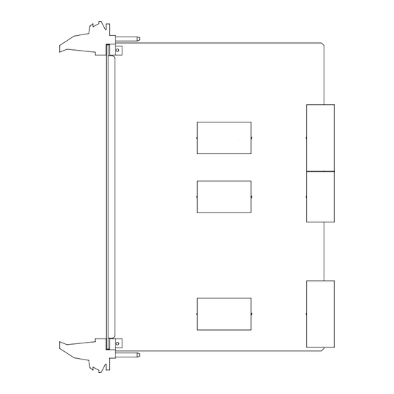
Page 17: Figure 2-1: Intallation For Mic-3950
Figure 2-1: Intallation for MIC-3950 MIC-3950 User's Manual... -
Page 18: Figure 2-2: Pmc Module Installation
Figure 2-2: PMC module installation Chapter 2 Hardware Installation... - Page 19 MIC-3950 User's Manual...
-
Page 20: Pin Assignments
Pin Assignments... -
Page 21: Mic-3950 J1 Connector Pin Assignments
A.1 MIC-3950 J1 connector pin assignments Table A-1: J1 connector pin assignments Row A Row B Row C Row D Row E +5 V REQ64# +5 V +5 V ACK64# +5 V M66EN C/BE0# AD12 AD11 AD10 AD15 AD14 AD13... -
Page 22: Mic-3950 J3 Connector Pin Assignments
A.2 MIC-3950 J3 connector pin assignments Table A-2: J3 connector pin assignments Pin Row A Row B Row C Row D Row E Row F 19 PMC24IO45 PMC24IO44 PMC24IO43 PMC24IO42 PMC24IO41 GND 18 PMC24IO50 PMC24IO49 PMC24IO48 PMC24IO47 PMC24IO46 GND 17 PMC24IO55 PMC24IO54 PMC24IO53 PMC24IO52 PMC24IO51 GND... -
Page 23: Mic-3950 J4 Connector Pin Assignment
A.3 MIC-3950 J4 Connector Pin Assignment Table A-3: J4 Connector Pin Assignment Pin# 12-14 KEY AREA PMC24IO5 PMC24IO4 PMC24IO3 PMC24IO2 PMC24IO1 PMC24IO10 PMC24IO9 PMC24IO8 PMC24IO7 PMC24IO6 PMC24IO15 PMC24IO14 PMC24IO13 PMC24IO12 PMC24IO11 GND PMC24IO20 PMC24IO19 PMC24IO18 PMC24IO17 PMC24IO16 GND PMC24IO25 PMC24IO24 PMC24IO23 PMC24IO22 PMC24IO21 GND... -
Page 24: Mic-3950 J11/J21 Pmc1/Pmc2 - Pci Connectors Pin Assignment
A.4 MIC-3950 J11/J21 PMC1/PMC2 - PCI Connectors Pin Assignment Table A-4: J11/J21 PMC1/PMC2 - PCI Connectors Pin Assignment Pin Function Pin Function Function Pin Function 17 REQ# FRAME# AD09 -12V 18 +5V 19 VIO INTA# 20 AD31 IRDY# C/BE0# INTB#... -
Page 25: Mic-3950 J12 Pmc1-Pci Connector Pin Assignment
A.5 MIC-3950 J12 PMC1-PCI Connector Pin Assignment Table A-5: J12 PMC1-PCI Connector Pin Assignment Pin Function Pin Function Pin Function Pin Function +12V PCI-RSVD AD08 TRST# PCI-RSVD +3.3V AD30 TRDY# AD07 AD29 +3.3V PCI-RSVD +3.3V AD26 STOP# PCI-RSVD AD24 PERR#... -
Page 26: Mic-3950 J14/J24 Pmc1/Pmc2 Rear-Panel I/O Connectors Pin Assignment
A.6 MIC-3950 J14/J24 PMC1/PMC2 Rear- Panel I/O Connectors Pin Assignment Table A-6: J14/J24 PMC1/PMC2 Rear-Panel I/O Connectors Pin A s s i g n m e n t Pin Function Pin Function Pin Function Pin Function 33 I/O 34 I/O... - Page 27 MIC-3950 User's Manual...
Need help?
Do you have a question about the MIC-3950 and is the answer not in the manual?
Questions and answers