Table of Contents
Advertisement
Quick Links
Advertisement
Table of Contents

Related Manuals for Advantech MIC-3640


Summary of Contents for Advantech MIC-3640
- Page 1 MIC-3640 Ultra2 Wide SCSI Card for Preface and Table of Contents...
- Page 2 All other product names or trademarks are properties of their respective owners. CE Notification The MIC-3640, developed by Advantech CO., LTD., has passed the CE test for environment specification when shielded cable are used for external wiring. We recommend the use of shielded cables.
- Page 3 Because of Advantech’s high quality-control standards and rigorous testing, most of our customers never need to use our repair service. If an Advantech product is defective, it will be repaired or replaced at no charge during the warranty period. For out-of-warranty repairs, you will be billed according to the cost of replacement materials, service time and freight.
- Page 4 If any of these items are missing or damaged, contact your distributor or sales representative immediately. Technical Support and Sales Assistance If you have any technical questions about the MIC-3640 or any other Advantech products, please visit our support website at: • http://support.advantech.com.tw...
-
Page 5: Table Of Contents
A.4 J1 connector pin assignments ............23 Figures Figure 2-1: MIC-3640 board layout: Dimensions ........7 Figure 2-2: MIC-3640 board layout: Connector locations ......8 Figure 2-3: MIC-3640 front panel connectors and locations ....10 Preface and Table of Contents... - Page 6 Tables Table 2-1: MIC-3640 connectors ..............9 MIC-3640 User's Manual...
-
Page 7: Chapter 1: Introduction
Introduction... -
Page 8: Description
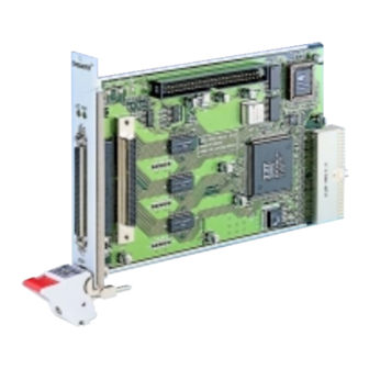
Description The MIC-3640 is a 3U-sized high-speed SCSI card for CompactPCI systems, which is compliant with CompactPCI specification 2.0 R2.1. The MIC-3640 uses the Symbios SYM53C895 SCSI processor to provide an Ultra2 wide SCSI interface with data transfer rate up to 80 MB/s. -
Page 9: Safety Precautions
1.3 Safety Precautions Follow these simple precautions to protect yourself from harm and the products from damage. 1. To avoid electric shock, always disconnect the power from your PC chassis before you work on it. Don't touch any components on the CPU card or other cards while the PC is on. - Page 10 MIC-3640 User's Manual...
-
Page 11: Chapter 2: Hardware And Drivers Installation
Hardware and Drivers Installation... -
Page 12: Initial Inspection
It should be free of marks and scratches and in perfect working order on receipt. As users unpack the MIC-3640, check it for signs of shipping damage (damaged box, scratches, dents, etc.). If it is damaged or fails to meet specifications, notify Advantech's service department or the local sales representative immediately. -
Page 13: Board Layout: Dimensions
Board Layout: Dimensions 160 mm 100 mm Figure 2-1: MIC-3640 board layout: Dimensions Chapter 2 Hardware and Drivers Installation... -
Page 14: Board Layout: Connector Locations
Board Layout: Connector Locations CN1 Int. 50-pin SCSI PWR LED (UP) ACT LED (DOWN) CN2 Ext. CN3 Int. 68 pin SCSI 68 pin SCSI Figure 2-2: MIC-3640 board layout: Connector locations MIC-3640 User's Manual... - Page 15 Table 2-1: MIC-3640 connectors Number Function Internal 50-pin SCSI connector External 68-pin SCSI connector Internal 68-pin SCSI connector PWR LED Power LED, ACT LED SCSI Activity LED The internal 50-pin SCSI connector (CN1) is an internal interface supporting Fast, Ultra, and Ultra Wide SCSI mode where the data transfer rate is 10, 20, and 40 MB/s respectively.
-
Page 16: Front Panel Connectors And Indicators
Front Panel Connectors and Indicators ® SCSI Figure 2-3: MIC-3640 front panel connectors and locations MIC-3640 User's Manual... -
Page 17: Card Installation
Card Installation The MIC-3640 is a PCI bus master card. It can be installed only in a CompactPCI slot which supports bus master function. Some proces- sor boards do not support bus master for each slot. Please refer to the user's manual of the processor board in use. -
Page 18: Utility User's Guide And Installation Instructions
INT13h SCSI disk drives and removable media devices using the ASPI manager. • VERIFY.HTM: SDMS DOS verify utility user's guide For Windows 95/98: • DEVMGR95.HTM: Installing the SYMC8XX.MPD/SYM_HI.MPD driver in Windows 95 • SCSITOOL.HTM: Installation guide for Symbios SCSI tools for Windows 95/98 and Windows NT MIC-3640 User's Manual... - Page 19 • WIN95.HTM: Installation guide for device drivers for Windows 95 and Windows 98 For Windows NT: • WINNT.HTM: Installation guide for device drivers for Windows NT • NEWASNT.HTM: Windows NT 4.0 guided installation for installing SYMC8XX or SYM_HI drivers • NTCONFG.HTM: Windows NT configuration utility (NTCONFIG) •...
-
Page 20: Building Driver Diskettes
• \SYM895\DISKIMAG\DOS_BIOS.EXE: DOS and SDMS SCSI BIOS • \SYM895\DISKIMAG\SCSITOOL.EXE: SCSI tools for Windows 95 and NT • \SYM895\DISKIMAG\8XXNT95.EXE: Drivers for Windows 95/NT • \SYM895\DISKIMAG\NW_OS2.EXE: Drivers for NetWare and OS/2 • \SYM895\DISKIMAG\NTCONFIG.EXE: Configuration utility for Windows NT • \SYM895\DISKIMAG\DOSUTILS.EXE: DOS configuration and format utility MIC-3640 User's Manual... -
Page 21: Driver And Utility Installation
2.8 Driver and Utility Installation The drivers and utilities for the SCSI interface are provided in the directories \SYM895\DRIVERS, \SYM895\UTILITY, and \SYM895\WINNT on the utility CD-ROM disc. The path and file names of the drivers and utilities are listed below. For DOS and Windows 3.1: •... - Page 22 MIC-3640 User's Manual...
-
Page 23: Appendix A: Pin Assignments
Pin Assignments... -
Page 24: Internal 50-Pin Scsi Connector (Cn1)
A.1 Internal 50-pin SCSI Connector (CN1) ..48 50 3 ..47 49 Table A-1: MIC-3640 Internal 50-pin SCSI connector Signal Signal SD+0 TPWEX SD-0 SD+1 SD-1 SD+2 SD-2 SATN+ SD+3 SATN- SD-3 SD+4 SD-4 SBSY+ SD+5 SBSY- SD-5 SACK+... -
Page 25: External 68-Pin Scsi Connector (Cn2)
A.2 External 68-pin SCSI Connector (CN2) 3 4 3 3 6 8 6 7 3 6 3 5 Table A-2: MIC-3640 External 68-pin SCSI connector Signal Signal SD+12 SD-12 SD+13 SD-13 SD+14 SD-14 SD+15 SD-15 SDP+1 SDP-1 SD+0 SD-0 SD+1... - Page 26 SMSG+ SMSG- SSEL+ SSEL- SCD+ SCD- SREQ+ SREQ- SIO+ SIO- SD+8 SD-8 SD+9 SD-9 SD+10 SD-10 SD+11 SD-11 MIC-3640 User's Manual...
-
Page 27: Internal 68-Pin Scsi Connector (Cn3)
A.3 Internal 68-pin SCSI Connector (CN3) 3 4 3 3 6 8 6 7 3 6 3 5 Table A-3: MIC-3640 Internal 68-pin SCSI connector Signal Signal SD+12 SD-12 SD+13 SD-13 SD+14 SD-14 SD+15 SD-15 SDP+1 SDP-1 SD+0 SD-0 SD+1... - Page 28 SMSG+ SMSG- SSEL+ SSEL- SCD+ SCD- SREQ+ SREQ- SIO+ SIO- SD+8 SD-8 SD+9 SD-9 SD+10 SD-10 SD+11 SD-11 MIC-3640 User's Manual...
-
Page 29: J1 Connector Pin Assignments
A.4 J1 connector pin assignments Table A-4: J1 connector pin assignments Row A Row B Row C Row D Row E REQ64# ENUM# +3.3V VI/O ACK64# +3.3V +3.3V +3.3V M66EN C/BE0# AD12 V I/O AD11 AD10 +3.3V AD15 AD14 AD13 SERR# +3.3V C/BE1#...
Need help?
Do you have a question about the MIC-3640 and is the answer not in the manual?
Questions and answers