
Related Manuals for Alcatel-Lucent 7210 SAS-D


Summary of Contents for Alcatel-Lucent 7210 SAS-D
- Page 1 7210 SAS-D NSTALLATION UIDE December 2011 Document Part Number: 93-0348-01-04 *93-0348-01-04*...
- Page 2 Copyright 2011 Alcatel-Lucent All rights reserved. No portion of this document may be reproduced in any form or means without prior written permission from Alcatel-Lucent. Information in this document is proprietary and confidential to Alcatel. The information in this document is subject to change. All trademarks and registered trademarks are the property of the respective owners.
-
Page 3: Table Of Contents
Physical Security ..............28 Installing the 7210 SAS-D Site Preparation . - Page 4 Booting a 7210 SAS-D from the Network ........
- Page 5 7210 SAS-D AC Chassis Front Panel Features ........
- Page 6 List of Tables Page 6 7210 SAS E Ethernet Service Switch...
- Page 7 7210 SAS-D ETR AC Chassis Front Panel........
- Page 8 List of Figures Page 8 7210 SAS-D Installation Guide...
-
Page 9: Preface
, and instructions to install and configure the 7210 SAS OS software. Each 7210 SAS-D switch is shipped with a console cable, power cord (AC or DC) and rubber feet. Optionally, a rack-mounting bracket kit, a wall-mounting bracket kit, and external AC or DC power module and bracket kit (ETR-only) are available for order. -
Page 10: Table 1: Information Symbols
Class 1 Laser Product Technical Support If you purchased a service agreement for your 7210 SAS-D and related products from a distributor or authorized reseller, contact the technical support staff for that distributor or reseller for assistance. If you purchased an Alcatel-Lucent service agreement, contact technical... -
Page 11: 7210 Sas-D Overview
7210 SAS-D Overview This chapter describes the 7210 SAS-D features and includes the following sections: • "Introduction" on page 12 • "Switch Features" on page 13 • "Switch Architecture" on page 15 • "Features" on page 16 • "Hardware Description" on page 18... -
Page 12: Introduction
Introduction Introduction 7210 SAS-D is an ethernet demarcation and backhaul unit with support for 4 x 10/100/1000 Base- T fixed ports and 6 x 100/1000 SFP ports, for use typically as a customer premise unit (CPE). It supports line-rate switching on all the ports. It is a service-aware Ethernet switch with support for QinQ layer-2 uplinks. -
Page 13: Switch Features
7210 SAS-D Overview Switch Features The 7210 SAS-D is a service-aware Layer 3 switch. It supports up to 10 connections including 6 100/1000 fiber-optic SFP ports and 4 10/100/1000 Base-T fixed copper ports. The chassis is available with either an AC power module or DC power module, as shown in the following... -
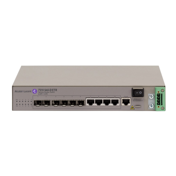
Page 14: Figure 3: 7210 Sas-D Etr Ac Chassis Front Panel
7210SASdc_0008 Figure 4: 7210 SAS-D ETR DC Chassis Front Panel All of the 7210 SAS-D variant chassis include the following features: • 6 100/1000 fiber-optic SFP ports and 4 10/100/1000 Base-T fixed copper ports • One RJ-45 console (RS-232 interface) connector for device management •... -
Page 15: Switch Architecture
7210 SAS-D Overview Switch Architecture The 7210 SAS-D employs a wire-speed, non-blocking switching fabric. This permits simultaneous wire-speed transport of multiple packets at low latency on all ports. The switch also features full- duplex capability on all ports, that effectively doubles the bandwidth of each connection. -
Page 16: Features
Supports intergrated AC or DC power supply. • The chassis does not use a fan for cooling. 7210 SAS-D ETR variant supports the following, in addition to the above features: • Supports extended temperature range (i.e. -40º C to 65º C) of operation •... -
Page 17: Connectivity
7210 SAS-D Overview Connectivity The 7210 SAS-D includes the following connectivity features: • 100/1000 fiber-optic SFP ports and 10/100/1000Base-T copper SFP ports full-duplex connections. The SFP ports allow for use of 10/100/1000 Base-T copper SFPs. • Auto-negotiation on 10/100/1000 Base-T fixed copper ports enables each port to automatically select the optimum speed and communication mode (half or full duplex) if this feature is supported by the attached device. -
Page 18: Hardware Description
The chassis is available with either an AC power module or DC power module, as shown in the following illustrations. AC Chassis 7210SASac_0001A Figure 5: 7210 SAS-D AC Chassis Front Panel 7210SASac_0001A Figure 6: 7210 SAS-D ETR AC Chassis Front Panel Page 18 7210 SAS-D Installation Guide... -
Page 19: Table 2: 7210 Sas-D Ac Chassis Front Panel Features
7210 SAS-D Overview The following section describes the front panel features of the 7210 SAS-D AC chassis: Table 2: 7210 SAS-D AC Chassis Front Panel Features Description Power, System, and Port LEDs 100/1000 SFP ports 10/100/1000Base-T fixed copper ports RJ-45 Console port... -
Page 20: Dc Chassis
Hardware Description DC Chassis 7210SASdc_0001A Figure 7: 7210 SAS-D DC Chassis Front Panel 7210SASdc_0001A Figure 8: 7210 SAS-D ETR DC Chassis Front Panel Page 20 7210 SAS-D Installation Guide... -
Page 21: Table 3: 7210 Sas-D Dc Chassis Front Panel Features
7210 SAS-D Overview The following section describes the front panel features of the 7210 SAS-D DC chassis: Table 3: 7210 SAS-D DC Chassis Front Panel Features Description Power, System, and Port LEDs 100/1000 SFP ports 10/100/1000Base-T fixed copper ports RJ-45 Console port... -
Page 22: Ethernet Interfaces
Hardware Description Ethernet Interfaces The 7210 SAS-D provides 6 100/1000 SFP ports. Each port can be used for a direct connection to a subscriber’s Customer Premises Equipment (CPE), or as an uplink to another aggregation node. The 7210 SAS-D also provides 4 10/100/1000Base-T fixed copper ports. -
Page 23: Power Modules
7210 SAS-D Overview Power Modules The 7210 SAS-D comes with an integrated AC or DC power supplies. 7210 SAS-D support two power supply options - universal AC and -48V DC. 7210 SAS-D ETR provides three option: universal AC, -48V DC and 24V DC. Additionally, 7210 SAS-D ETR supports and optional external backup power supply. -
Page 24: External Power Modules (Etr-Only)
The external power module is available as as AC module or a DC module. Note: 7210 SAS-D does not support detection of failure of the external backup power supply. It also does not support for detection of power source failure when an external backup power supply is in use. -
Page 25: Table 6: External Dc Power Module Description
Pins 3 and 4 are not connected or recommended. Table 6: External DC Power Module Description Description Front view of the External DC Power module. Rear view of the External DC Power module. Captive screw. Connecting cable to the SAS-D chassis. 7210 SAS-D Installation Guide Page 25... -
Page 26: System And Port Leds
System LED Port LEDs Table 8: System LED Condition Status Status Green Indicates that the system has completed boot phase and is running normally. Amber Indicates that the device is in an alarm state. Page 26 7210 SAS-D Installation Guide... -
Page 27: Power Switch
Figure 13: Location of the Power Switch Table 10: Front Panel Power Switch Button/Switch Condition Status Power Module Switch Standby mode if switch is connected to a power source. AC or DC power is applied to the switch. 7210 SAS-D Installation Guide Page 27... -
Page 28: Physical Security
Hardware Description Physical Security 7210 SAS-D provides a security slot to be used to attach to a lock-and-cable security apparatus. The security slot is located on the upper right side of the back panel of the chassis. Page 28 7210 SAS-D Installation Guide... -
Page 29: Installing The 7210 Sas-D
Installing the 7210 SAS-D This chapter describes site preparation and installation of your 7210 SAS-D and includes the following sections: • "Site Preparation" on page 30 • "Installing Your Switch" on page 32 7210 SAS-D Installation Guide Page 29... -
Page 30: Site Preparation
Site Preparation Selecting a Site You can mount the 7210 SAS-D in a standard 19-inch equipment rack, on a flat surface or mount it on a wall. When mounting on a flat surface, ensure that the four rubber feet are installed on the bottom of the box. -
Page 31: Equipment Checklist
• Make sure you only use SFPs that are supported by Alcatel-Lucent. Equipment Checklist After unpacking your switch, check the contents to make sure all the components are present. -
Page 32: Installing Your Switch
Bracket mounting kit, including the four mounting screws for each device you plan to install in a rack (not included, and sold separately as: 3HE06696AA 7210 SAS-D rack mount kit) • A screwdriver (Phillips or flathead, depending on the type of screws used) -
Page 33: Installing The 7210 Sas-D
Installing the 7210 SAS-D Mount the 7210 SAS-D in the rack, using four rack-mounting screws (not Step 2 provided). See Figure 7210SASac_0005 Figure 15: Installing the Switch in a Rack If you are installing a single switch, proceed to "Grounding the Chassis" on... -
Page 34: Desktop Or Shelf Mounting
If you are installing a single switch, proceed to "Grounding the Chassis" on page If you are installing multiple switches, attach four adhesive feet to each Step 4 switch. Place each device squarely on top of the one below, in any order. Page 34 7210 SAS-D Installation Guide... -
Page 35: Wall Mounting
Installing the 7210 SAS-D Wall Mounting Step 1 Measure the distance between the two wall mounting screw guides located on the bottom of the chassis. Secure the two wall mounting screws to the desired location on the wall. See Step 2... -
Page 36: Grounding The Chassis
Ground per local electrical codes. Step 5 Attach the grounding wire to the ground points on the rack. 7210SASac_0001 CAUTION The earth connection must not be removed unless all supply connections have been disconnected. Page 36 7210 SAS-D Installation Guide... -
Page 37: Connecting To A Power Source
Installing the 7210 SAS-D Connecting to a Power Source This SAS-D switch is available with either an AC or DC internal power supply modules. The SAS-D switch is also compatible with either an AC or DC (available as a separate purchase) external power supply. -
Page 38: Connecting To A Dc Power Source
(see "Appendix A: Specifications" on page 79). Step 3 The wiring between the DC power supply and the switch must be stranded copper wire within the range of 10 to 24 AWG. Page 38 7210 SAS-D Installation Guide... -
Page 39: Figure 18: Connecting A -48 Vdc Power Source
Installing the 7210 SAS-D Connect the -48 VDC power feed using the -48 VDC input and RET (return) Step 4 lines. Insert the wires into the DC input plug (using a small flat-tip screwdriver). Color code the wiring according to local standards to ensure that the input power and ground lines can be easily distinguished. - Page 40 (see "Appendix A: Specifications" on page 79). The wiring between the DC power supply and the switch must be stranded Step 3 copper wire within the range of 10 to 24 AWG. Page 40 7210 SAS-D Installation Guide...
-
Page 41: Figure 19: Connecting A +24 Vdc Power Source
Installing the 7210 SAS-D Connect the +24 VDC power feed using the GND (ground) and +24 VDC Step 4 input lines. Insert the wires into the DC input plug (using a small flat-tip screwdriver). Color code the wiring according to local standards to ensure that the input power and ground lines can be easily distinguished. -
Page 42: Connecting To The Console Port
Used as defined. Should be connected Used as defined. Should be connected Used as defined. Should be connected Used as defined. Should be connected Not used. Should not be connected Used as defined. Should be connected Page 42 7210 SAS-D Installation Guide... -
Page 43: Installing The Optional External Power Supply (Etr Only)
Mounting kit for the external power supply, sold separately • A screwdriver (Phillips or flathead, depending on the type of screws used) To install your external power supply to the 7210 SAS-D ETR: (Front view) Assemble and secure the brackets to the switch and the external Step 1 power module using the screws provided in the External Power Supply Mounting Kit. -
Page 44: Figure 21: Attaching The External Power To The Chassis Using The Mounting Kit (Rear View)
Figure 21: Attaching the External Power to the Chassis Using the Mounting Kit (Rear View) Step 3 Connect the external power module’s power cable to the switch chassis. See Figure 22 on page 7210SASdc_0012 Figure 22: Connecting the Power Cable from the External Power Module to the Chassis Page 44 7210 SAS-D Installation Guide... - Page 45 Installing the 7210 SAS-D 7210 SAS-D Installation Guide Page 45...
- Page 46 Installing Your Switch Page 46 7210 SAS-D Installation Guide...
- Page 47 This chapter describes how to replace Small Form Factor Pluggable (SFP) ports that support these devices. • "Warnings and Notes" on page 48 • "Installation Preparation" on page 49 7210 SAS-D Installation Guide Page 47...
-
Page 48: Warnings And Notes
• Do not remove the dust cover on the connector until you are ready to install the SFP. Always replace the the dust cover when the SFP is removed. Notes: • Discard SFPs according to all local laws and regulations. • SFPs are keyed to prevent incorrect insertion. Page 48 7210 SAS-D Installation Guide... -
Page 49: Installation Preparation
Blow dry the ferrule with compressed air and inspect for lint. Do not insert the compressed air nozzle into the receptacle when blowing out. Locking Mechanisms Alcatel-Lucent SFPs can use different lock and release methods. Possible lock and release mechanisms include: •... -
Page 50: Installing Sfps
Connect the network cable or place a safety cap over the optical transceiver. Step 5 7210 SAS-D does not use a fan for cooling and the SFPs might be Caution: slightly hotter than usual. Avoid direct contact with the metal casing of the SFPs. -
Page 51: Configuring The 7210 Sas-D
Configuring the 7210 SAS-D This chapter describes how to configure your 7210 SAS-D and contains the following sections: • "Diagnostics" on page 52 • "Initializing the System and Downloading Software" on page 53 • "Establishing Switch Connections" on page 69... -
Page 52: Diagnostics
After successfully installing the switch, ensure that the LEDs show the following state: • Sys: GREEN • Power: GREEN If any of the LEDs shows a different state, toggle the power switch slowly and wait for a few seconds to let the system boot. Page 52 7210 SAS-D Installation Guide... -
Page 53: Initializing The System And Downloading Software
Booting a 7210 SAS-D in the Lab There are several ways to boot the 7210 SAS-D from the network. User can choose to boot the device using one of the following options: •... -
Page 54: Booting A 7210 Sas-D Using The Image On Flash (With The Image Shipped By Factory)
Initializing the System and Downloading Software Booting a 7210 SAS-D using the image on Flash (with the image shipped by factory) You will need the following: • A PC with a serial port and Hyperterminal • Cable that connects the console port of SAS-D to the serial port of PC Connect the 7210's console port to serial port of the PC and then power on the 7210 SAS-D. -
Page 55: Configuring The 7210 Sas-D
Configuring the 7210 SAS-D TiMOS BOOT LOADER Time from clock is THU APR 21 11:03:21 2011 UTC Switching serial output to sync mode... done Since the switch does not ship with a BOF, it will show the default settings. Looking for cf1:/bof.cfg ... - Page 56 TiMOS. The file can be on a Compact Flash device, or on the network. Here are some examples cf1:/config.cfg ftp://user:passwd@192.168.1.150/./config.cfg tftp://192.168.1.150/./config.cfg No existing Config URL Press ENTER, or type 'none' for no Config URL. Config File URL: Page 56 7210 SAS-D Installation Guide...
- Page 57 + data:(3179598-->18748616) Executing TiMOS image at 0x100000 After the 7210 SAS-D boots up, you should see the following prompt: All rights reserved. All use subject to applicable license agreements. Built on Wed Apr 20 14:32:04 IST 2011 by builder in /builder/3.0B5/panos/...
-
Page 58: Booting A 7210 Sas-D From The Network
Initializing the System and Downloading Software The default username and password are admin. Log into the 7210 SAS-D. The SYS LED will be Green when the device has successfully completed the boot Note: process and is running normally. To establish either console connection or Telnet connection to the router after successful boot, please see "Establishing Switch Connections"... - Page 59 A network cable to connect the 7210 unit to the network Prepare the set up as shown in the diagram above. When you are done, power on the 7210 SAS-D. Using the uplink port to boot 7210 from the network: Resetting...OK...
-
Page 60: Default Settings
You must supply some required Boot Options. At any prompt, you can type: "restart" - restart the query mode. "reboot" - reboot. "exit" - boot with with existing values. "diag" - enter the diag shell. "reset" - reset the bof and reboot. Page 60 7210 SAS-D Installation Guide... - Page 61 Configuring the 7210 SAS-D Press ENTER to begin, or 'flash' to enter firmware update... Press Enter. Software Location ----------------- You must enter the URL of the TiMOS software. The location can be on a Compact Flash device, or on the network.
- Page 62 Enter the port which it connected to the network (for example, 1/1/10). You need to assign an IP address for this port. The IP address should be entered in standard dotted decimal form with a network length. example: 192.168.1.169/10 Page 62 7210 SAS-D Installation Guide...
- Page 63 Configuring the 7210 SAS-D Or type "0" to obtain IP address and static route through DHCP. Existing IP address and static routes will be deleted. uplinkA port is configured to obtain IP address and static route through dhcp. Press ENTER to keep it.
- Page 64 115200 Do you want to overwrite cf1:/bof.cfg with the new settings? (yes/no): Type yes and press Enter. The 7210 SAS-D should boot now. Primary image location: ftp://*:*@10.10.170.22/./images/both.tim Initializing uplinkA port using IP addr 10.135.4.172. Loading image ftp://*:*@10.10.170.22/./images/both.tim Version B-3.0.R4, Wed Apr 20 22:44:35 IST 2011 by builder in /builder/3.0B5/ R4/panos/main text:(25061599-->122246984) + data:(3180415-->18748616)
- Page 65 Configuring the 7210 SAS-D Executing TiMOS image at 0x100000 After the 7210 SAS-D boots up, you should see the following Login prompt: All rights reserved. All use subject to applicable license agreements. Built on Wed Apr 20 22:44:35 IST 2011 by builder in /builder/3.0B5/R4/panos/...
-
Page 66: Downloading The Timos Software To The Internal Flash
Configure an IES service. A:SN12# configure service A:SN12>config>service# info ---------------------------------------------- customer 1 create description "Default customer" exit ies 2 customer 1 create interface "in-band-mgmt" create address 10.135.4.172/10 sap 1/1/10:0.* create exit exit no shutdown exit ---------------------------------------------- A:SN12>config>service# Page 66 7210 SAS-D Installation Guide... - Page 67 Configuring the 7210 SAS-D Configure a route to the FTP server. A:SN12#configure router A:SN12>config>router# A:SN12>config>router# static-route 10.10.170.0/10 next-hop 10.135.4.1 A:SN12>config>router# Check IP connectivity: A:SN12# ping 10.10.170.22 source 10.135.4.172 PING 10.10.170.22 56 data bytes 64 bytes from 10.10.170.22: icmp_seq=1 ttl=251 time<1ms.
- Page 68 A:SN12# bof primary-image cf1:/both.tim *A:SN12# bof save Writing BOF to cf1:/bof.cfg Saving BOF ..Completed. A:SN12# Reboot the SAS-D. The device will pick up both the image and the configuration from the internal flash. Page 68 7210 SAS-D Installation Guide...
-
Page 69: Establishing Switch Connections
Configuring the 7210 SAS-D Establishing Switch Connections Access your newly installed switch two ways: • "Console Connection" on page 69 • "Telnet Connection" on page 70 Console Connection To establish a console connection, you will need the following: • An ASCII terminal or a PC running terminal emulation software set to the parameters shown in the table below •... -
Page 70: Telnet Connection
Telnet access provides the same options for user and administrator access as those available through the console port. To configure the 7210 SAS-D for Telnet access, you must have a device with Telnet software located on the same network. The 7210 SAS-D must have a management IP interface configured with an IP address. -
Page 71: Running Telnet
The 7210 SAS-D must have a management IP address. The IP address is manually configured. Running Telnet Once the IP parameters are configured, you can access the CLI command line with a Telnet connection. - Page 72 Establishing Switch Connections Page 72 7210 SAS-D Installation Guide...
-
Page 73: Troubleshooting
This chapter describes troubleshooting methods and procedures and includes the following sections: • "Diagnosing Switch Indicators" on page 74 • "Power Problems" on page 75 • "Installation" on page 76 • "In-Band Access" on page 77 7210 SAS-D Installation Guide Page 73... -
Page 74: Diagnosing Switch Indicators
• Verify that the proper cable type is used and its length does not exceed specified limits. • Check the adapter on the attached device and cable connections for possible defects. Replace the defective adapter or cable if necessary. Page 74 7210 SAS-D Installation Guide... -
Page 75: Power Problems
However, if the unit powers off after running for a while, check for loose power connections, power losses or surges at the power. 7210 SAS-D Installation Guide Page 75... -
Page 76: Installation
Verify that all system components have been properly installed. If one or more components appear to be malfunctioning (such as the power cord or network cabling), test them in an alternate environment where you are sure that all the other components are functioning properly. Page 76 7210 SAS-D Installation Guide... -
Page 77: In-Band Access
NOTE: The management agent can accept up to four simultaneous Telnet sessions. If the maximum number of sessions already exists, an additional Telnet connection will not be able to log into the system. 7210 SAS-D Installation Guide Page 77... - Page 78 In-Band Access Page 78 7210 SAS-D Installation Guide...
-
Page 79: Appendix A: Specifications
Appendix A: Specifications This appendix provides system specifications and includes the following sections: • "Specifications" on page 80 7210 SAS-D Installation Guide Page 79... -
Page 80: Specifications
Specifications Specifications 7210 SAS-D Platform The following specifications are for the 7210 SAS-D (non-ETR) chassis. Table 14: 7210 SAS-D Specifications Item Width Height Depth Physical dimensions Size 10.43" (26.5 cm) 1.69" (1.5RU) (4.28 6.89" (17.5 cm) Weight 3 lbs. (1.36 kg) - Page 81 Appendix A: Specifications Table 14: 7210 SAS-D Specifications (Continued) Item Width Height Depth Europe CE Mark: EN55022 Class A EN 300 386 North America: FCC 47 CFR Part 15 Class A ICES-003 Class A (Canada) Japan: VCCI CISPR 22 Class A...
-
Page 82: 7210 Sas-D Etr Platform
Specifications 7210 SAS-D ETR Platform The following specifications are for the 7210 SAS-D ETR chassis. Table 15: 7210 SAS-D Specifications Item Width Height Depth Physical dimensions Size 10.5" (26.7 cm) 1.75" (1.5RU) (4.4 cm) 7.0" (17.8 cm) Weight 3 lbs. (1.36 kg) - Page 83 Appendix A: Specifications Table 15: 7210 SAS-D Specifications (Continued) Item Width Height Depth Europe CE Mark: EN55022 Class A EN 300 386 North America: FCC 47 CFR Part 15 Class A ICES-003 Class A (Canada) Japan: VCCI CISPR 22 Class A...
-
Page 84: Japan Vcci Class A Declaration
When such trouble occurs, the user may be required to take corrective actions. RoHS and WEEE Comply with European RoHS and WEEE requirements. Comply with the Chinese RoHS legislations. Page 84 7210 SAS-D Installation Guide... -
Page 85: Appendix B: Console Connection
Appendix B: Console Connection This appendix provides port specifications about console port: • "Console Port Pin Assignment" on page 86 7210 SAS-D Installation Guide Page 85... -
Page 86: Console Port Pin Assignment
Used as defined. Should be connected Used as defined. Should be connected Used as defined. Should be connected Used as defined. Should be connected Not used. Should not be connected Used as defined. Should be connected Page 86 7210 SAS-D Installation Guide... -
Page 87: Appendix B: Console Connection
Appendix B: Console Connection 7210 SAS-D Installation Guide Page 87... - Page 88 Console Port Pin Assignment Page 88 7210 SAS-D Installation Guide...
Need help?
Do you have a question about the 7210 SAS-D and is the answer not in the manual?
Questions and answers