
Related Manuals for KTI Networks KGC-320


Summary of Contents for KTI Networks KGC-320
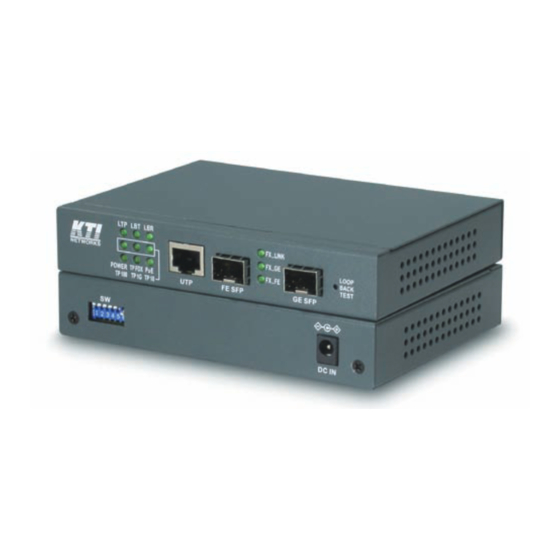
- Page 1 KGC-320, KGC-320-HP Web Smart Gigabit Ethernet Media Converter 10/100/1000BASE-T to 100/1000BASE-X Installation Guide DOC.120925...
- Page 2 (C) 2012 KTI Networks Inc. All rights reserved. No part of this documentation may be reproduced in any form or by any means or used to make any directive work (such as translation or transformation) without permission from KTI Networks Inc.
- Page 3 The information contained in this document is subject to change without prior notice. Copyright (C) All Rights Reserved. TRADEMARKS Ethernet is a registered trademark of Xerox Corp. FCC WARNING AND NOTICE This equipment has been tested and found to comply with the limits for a Class A digital device, pursuant to Part 15 of the FCC Rules.
-
Page 4: Table Of Contents
Table of Contents 1. Introduction ..........................6 1.1 Features ........................ 7 1.2 Product Panels...................... 8 1.3 Specifications ......................9 1.4 Model Definition ....................12 1.5 Optical Specifications..................12 2. Installation........................... 13 2.1 Unpacking ......................13 2.2 Safety Cautions....................13 2.3 Mounting the Media Converter................14 2.4 Applying Power .................... - Page 5 4.4 System ........................ 31 4.4.1 Management VLAN..................33 4.5 Ports........................35 4.5.1 802.1Q Filtering ....................37 4.6 IGMP Snooping....................38 4.7 Storm Control ...................... 39 4.8 Statistics......................40 4.9 Detailed Statistics....................41 4.10 IGMP Status...................... 42 4.11 Loopback Test ....................43 4.12 Reboot System ....................
-
Page 6: Introduction
1. Introduction The device is a Gigabit Ethernet media converter series which provide the following features: Data Conversion between different Media types and Speed The media converter supports the following conversions: 1000Mbps (1000BASE-T) copper to/from 1000Mbps (1000BASE-X) fiber 100Mbps (1000BASE-TX) copper to/from 1000Mbps (1000BASE-X) fiber ... -
Page 7: Features
This feature can force the link to shut down as soon as it notices that the other link has failed. It allows a link partner on one cable segment can notice a link fault occurred on the other segment and give application a chance to react. -
Page 8: Product Panels
Copper port auto-negotiation mode, speed and duplex configuration by DIP switch settings With optional model, copper port provide PoE+ power source (PSE) function. The Link Fault Pass Through function allows link fault status passes through between copper link and fiber link transparently. -
Page 9: Specifications
1.3 Specifications Twisted-pair RJ-45 Copper Port Compliance IEEE 802.3 10Base-T, IEEE 802.3u 100Base-TX, IEEE 802.3u 1000Base-T Connectors Shielded RJ-45 jacks Pin assignments Auto MDI/MDI-X detection Configuration Auto-negotiation, manual settings or software control Transmission rate 10Mbps, 100Mbps, 1000Mbps Duplex support Full/Half duplex Network cable Cat.5 UTP Gigabit Ethernet SFP for Fiber Port... - Page 10 LED Indicators Local or remote TP indication on TP LEDs Loop-back test in-progress LED Loop-back test result LED TP1G Twisted-pair copper port 1000Mbps and link status TP100 Twisted-pair copper port 100Mbps and link status TP10 Twisted-pair copper port 10Mbps and link status POWER Power status TPFDX...
- Page 11 37W @56V (Including full PoE output) Mechanical Dimension (base) 144 x 104.5 x 26 mm Housing Enclosed metal with no fan Mounting Desktop mounting, wall mounting, optional Din-rail mounting Environmental Operating Temperature Typical -10ºC ~ +50ºC Storage Temperature -40ºC ~ +85ºC Relative Humidity 10% ~ 90% Electrical Approvals...
-
Page 12: Model Definition
1.4 Model Definition KGC-320-HP PoE Model Media converter with PoE+ PSE function KGC-320 Non-PoE Model Media converter with no PoE+ PSE function 1.5 Optical Specifications KGC-320-HP-XXX, KGC-320-XXX (XXX: model extension) Wavelength Tx Power Sensitivity Rx Max. Model Ext. 1000M Fiber Distance... -
Page 13: Installation
2. Installation 2.1 Unpacking The product package contains: The media converter unit One product CD-ROM 2.2 Safety Cautions To reduce the risk of bodily injury, electrical shock, fire and damage to the product, observe the following precautions: Do not service any product except as explained in your system documentation. -
Page 14: Mounting The Media Converter
2.3 Mounting the Media Converter The media converter can be mounted on a desktop or shelf or a wall and in a Din-rail enclosure. Make sure that there is proper heat dissipation from and adequate ventilation around the device. Do not place heavy objects on the device. -
Page 15: Applying Power
The following figure illustrates the converter is installed with Din-Rail mounting bracket: 2.4 Applying Power Before you begin the installation, check the AC voltage of your area. The AC power adapter which is used to supply the DC power for the unit should have the AC voltage matching the commercial power voltage in your area. -
Page 16: Making Fiber Connection
10BASE-T: 2-pair UTP Cat. 3,4,5 , EIA/TIA-568B 100-ohm 100BASE-TX: 2-pair UTP Cat. 5, EIA/TIA-568B 100-ohm 1000BASE-T: 4-pair UTP Cat. 5 or higher (Cat.5e is recommended), EIA/TIA-568B 100-ohm Link distance: Up to 100 meters Auto MDI/MDI-X Function This function allows the port to auto-detect the twisted-pair signals and adapts itself to form a valid MDI to MDI-X connection with the remote connected device automatically. - Page 17 Your device unit may come with an SFP transceiver pre-installed when it was delivered. Installing SFP Fiber Transceiver To install an SFP fiber transceiver into an SFP slot, the steps are: 1. Turn off the power to the device unit. 2.
-
Page 18: Loop-Back Test Push Button
FE_SFP 100Mbps Full 100BASE-FX 2.7 Loop-back Test Push Button The push button is used to perform loop-back test between two media converters connected with fiber cable as shown below: It allows installer to perform diagnostic to the fiber link during installation and check the test result displayed on the LED indicators. -
Page 19: Configuration Dip Sw
2.8 Configuration DIP SW The configuration DIP SW (switches) is used for setting operation configuration manually. The functions of each DIP SW states are: Function Ignore DIP SW6 SW5 SW4 settings (Use software configuration for managed model) Set TP Port in non-auto, 10Mbps, Full duplex mode Set TP Port in non-auto, 10Mbps, Half duplex mode Set TP Port in non-auto, 100Mbps, Full duplex mode Set TP Port in non-auto, 100Mbps, Half duplex mode... -
Page 20: Led Indication
2.9 LED Indication Function State Interpretation POWER Power status The power is supplied to the unit. The power is not supplied to the unit. Local TP status * Local TP port status displayed on TPxxx LEDs Remote TP port status displayed on TPxxx LEDs Blink Fail to display remote TP port status *1: LTP is always ON if remote TP status auto-report function is disabled. -
Page 21: Configuring Ip Address And Password For The Device
2.10 Configuring IP Address and Password for the Device For managed model, the device unit is shipped with the following factory default settings for software management: Default IP address of the device: 192.168.0.2 / 255.255.255.0 The IP Address is an identification of the device unit in a TCP/IP network. Each unit should be designated a new and unique IP address in the network. -
Page 22: Functions
3. Functions To help a better understanding about the software management interfaces, this chapter describes some advanced functions provided by the media converter. 3.1 Abbreviation TP Port: The twisted-pair copper port of the media converter device. FX Port: The optical fiber port of the media converter device. Ingress Port: Ingress port is the input port on which a packet is received. -
Page 23: Link Fault Pass Through Function
The data rate on twisted-pair segment depends on the link speed finally established with the link partner. 3.3 Link Fault Pass Through Function Description When the Link Fault Pass Through (LFPT) function is enabled and the media converter detects a link fault on one port segment, it will force the other port segment link down. -
Page 24: Remote Tp Status Monitoring Function
occurs in any cable segment. Methods to enable the function The LFPT function can be enabled by: Hardware setting: DIP SW6 is set to ON position Software setting: Web management -> Configuration -> System -> [Link fault pass through] 3.4 Remote TP Status Monitoring Function Description The local media converter can monitor the TP port link status of its remote link partner connected on the fiber cable. -
Page 25: 802.1Q Control Function
TPFDX ON Remote TP link in full duplex Remote TP link in half duplex 2. Web management -> Monitoring -> Statistics -> Remote TP [Link] 3.5 802.1Q Control Function 802.1Q Control function allows perform 802.1Q VLAN related operation to the packets passing through the media converter according packet contents as follows: [Ingress Drop] setting The setting is the first filtering mechanism to filter all incoming untagged packets or to filter all incoming... -
Page 26: Snmp Support
Enable Disable All packets are with no modification. Disable Disable All packets are untagged in egress. Disable Enable All packets are tagged in egress. Enable Enable Settings not recommended (possible double-tagging) [Ingress Keep Tag] options: Enable - The VLAN tag in the received VLAN-tagged packet will be kept as it is and is not stripped in whole conversion operation. - Page 27 The media converter is equipped with SNMP support. It can be managed from remote SNMP manager stations over SNMP protocol. SNMP version support SNMP v1, v2c management Managed Objects MIB-II system OBJECT IDENTIFIER ::= { mib-2 1 } interfaces OBJECT IDENTIFIER ::= { mib-2 2 } OBJECT IDENTIFIER ::= { mib-2 4 } snmp OBJECT IDENTIFIER ::= { mib-2 11 }...
- Page 28 SNMP Trap events The following events are defined for generating a trap message when the event occurs on the unit. The device boot up. TP copper port link down TP copper port link up (link recovery). FX fiber port link down ...
-
Page 29: Web Management
4. Web Management The media converter features an http server which can serve the management requests coming from any web browser software over TCP/IP network. Web Browser Compatible web browser software with JAVA script support Microsoft Internet Explorer 4.0 or later Set IP Address for the System Unit Before the device unit can be managed from web browser software, make sure a unique IP address is configured for the unit. -
Page 30: Main Management Menu
The device will accept only one successful management connection at the same time. The other connection attempts will be prompted with a warning message. A new connection will be accepted when the current user logout successfully or auto logout by the device due to no access for time out of 3 minutes. -
Page 31: System
Detailed Statistics List detailed statistics for all ports IGMP Status IGMP snooping status Maintenance Loopback Test Command to perform loop-back test on fiber link Reboot System Command to reboot the device unit Restore Default Command to restore the device unit with factory default settings Update Firmware Command to update the device firmware Configuration File Command to transfer (upload/download) configuration file Transfer... - Page 32 Configuration Description MAC Address The MAC address factory configured for the switch It can not be changed in any cases. S/W Version The firmware version currently running H/W Version The hardware version currently operating Active IP Address Currently used IP address for the switch management Active Subnet Mask Currently used subnet mask for IP address for the switch management Active Gateway...
-
Page 33: Management Vlan
DHCP Enabled Use DHCP to get dynamic IP address configuration for the device Fallback IP Address IP address used when DHCP mode is not enabled Fallback Subnet Mask Subnet mask for IP address used when DHCP mode is not enabled Fallback Gateway Default gateway IP address used when DHCP mode is not enabled Management VLAN... - Page 34 1. If the 802.1Q Control function is disabled, Management VLAN settings are ignored and no VLAN limitation is applied in accessing the web management interface. The http server only accepts untagged management packets and replies untagged packets to the management host. 2.
-
Page 35: Ports
4.5 Ports Ports Configuration has three major parts as follows: Port Configuration Port link status, port operating mode, port flow control and PoE function 802.1Q Control 802.1Q Control per port settings Port Configuration Function Port UTP - Twisted-Pair copper port, SFP - Fiber port Link Port link status Speed and duplex status with green background - port is link on... - Page 36 10 Full Disable Full 100 Half Disable 100M Half 100 Full Disable 100M Full 1000 Full Enable 1000M Full FX Mode Auto-negotiation Speed capability Duplex capability Disable - Disable port operation Auto (GE preference) – Auto-selection for GE SFP or FE SFP by detection of the slot which was installed with SFP transceiver.
-
Page 37: 802.1Q Filtering
Refresh Click to refresh the page. Any changes made locally will be undone. 4.5.1 802.1Q Filtering Configuration Description VID TABLE Specify the characteristic of the VID table. Disable - set to disable 802.1Q filtering function. Allowed VID - the VID table specifies the allowed VIDs Rejected VID - the VID table specifies the rejected VIDs Entry of VID table - up to 16 VIDs can be configured in VID table 1 ~ 4095 - decimal 12-bit VID value... -
Page 38: Igmp Snooping
3. [Rejected VID] setting is useful when only certain VIDs are not allowed to pass the device. 4.6 IGMP Snooping Configuration Description IGMP Enabled Check to enable global IGMP snooping. Router Ports Specify which ports have multicast router connected and require being forwarding IPMC packets unconditionally. -
Page 39: Storm Control
4.7 Storm Control Configuration Description Broadcast Rate The rate limit of the broadcast packets transmitted on a port. Multicast Rate The rate limit of the Multicast packets transmitted on a port. Flooded Unicast Rate The rate limit of the flooded unicast packets transmitted on a port. The flooded unicast packets are those unicast packets whose destination address is not learned in the MAC address table. -
Page 40: Statistics
4.8 Statistics Configuration Description Port UTP - Twisted-Pair copper port on local unit SFP - Fiber port on local unit Remote TP - TP port of the remote unit connected on the fiber link Link Port link status Speed and duplex status with green background - port is link on Down with red background - port is link down Tx Bytes Total of bytes transmitted on the port... -
Page 41: Detailed Statistics
4.9 Detailed Statistics Button Description Click to display all statistic counters of UTP port. Click to display all statistic counters of Fiber port. Clear Click to reset all statistic counters. Refresh Click to refresh the displayed statistic counters. -41-... -
Page 42: Igmp Status
4.10 IGMP Status Status Description VLAN ID The VLAN ID of the entry. Querier Status Show the Querier status is “Active” or “Idle”. Queries transmitted The number of Transmitted Queries. Queries Received The number of Received Queries. V1 Reports The number of Received V1 Reports. V2 Reports The number of Received V2 Reports. -
Page 43: Loopback Test
4.11 Loopback Test This menu is used to start a loopback test operation with the link partner unit over the fiber link. The message displayed during test is: The result message displayed after a test finished is: The test result is also displayed on LEDs - LBT and LBR. 4.12 Reboot System This menu is used to reboot the device unit remotely with current configuration. -
Page 44: Update Firmware
This menu is used to restore all settings of the device unit with factory default values. Note that this menu might change the current IP address of the device and make your current http connection lost. 4.14 Update Firmware This menu is used to perform in-band firmware (software) upgrade. Enter the path and file name of new firmware image file for uploading. -
Page 45: Configuration File Transfer
4.15 Configuration File Transfer This [download] command can be used to backup current switch configuration and download it to the connected management PC using default filename, switch.cfg. Configuration Description Filename Path and filename of a backup configuration file to be uploaded Browse Click to browse your computer file system for the configuration file Upload... -
Page 46: Appendix A. Factory Default Settings
Appendix A. Factory Default Settings Configuration DIP SW Unmanaged Model Managed Model SW3 SW2 SW1 ON ON ON OFF OFF OFF Auto,10/100/100,Full/Half Web configuration (SW4-6 ignored) OFF (Enable flow control) OFF (Disable remote TP auto report) OFF (Disable link fault pass through) System Configuration DHCP Enabled... - Page 47 Enable for PoE model Ingress Drop Disable Ingress Keep Tag Enable Egress Insert Tag Disable Default Tag - VID (PVID) Default Tag - CFI Default Tag - Priority 802.1Q Filtering Configuration VID TABLE Disable VID n (n=1-16) -47-...
Need help?
Do you have a question about the KGC-320 and is the answer not in the manual?
Questions and answers