
Related Manuals for KTI Networks KGC-310M-C


Summary of Contents for KTI Networks KGC-310M-C
- Page 1 Web Smart Gigabit Ethernet Media Converter KGC-310M-C F/W: KGC-310M-C 1.023 up F/W: KGC-310M RC 1.028 up Installation Guide DOC.181122...
- Page 2 KTI Networks Inc. KTI Networks Inc. reserves the right to revise this documentation and to make changes in content from time to time without obligation on the part of KTI Networks Inc. to provide notification of such revision or change.
- Page 3 The information contained in this document is subject to change without prior notice. Copyright (C) All Rights Reserved. TRADEMARKS Ethernet is a registered trademark of Xerox Corp. FCC NOTICE This device complies with Class A Part 15 the FCC Rules. Operation is subject to the following two conditions: (1) This device may not cause harmful interference, and (2) this device must accept any interference received including the interference that may cause.
-
Page 4: Table Of Contents
Table of Contents 1. Introduction ........................... 6 1.1 Features ......................7 1.2 Product Panels ....................9 1.3 Specifications ...................... 9 2. Installation ...........................12 2.1 Unpacking ......................12 2.2 Safety Cautions ....................12 2.3 Mounting the Media Converter ................13 2.4 Applying Power ....................15 2.5 Making UTP Connections.................. - Page 5 4.4.3 LLDP ......................43 4.5 Monitoring ......................45 4.5.1 Statistics Overview ..................45 4.5.2 LLDP Statistics ....................46 4.5.3 LLDP Table ....................47 4.5.4 Ping........................ 48 4.6 Maintenance ..................... 49 4.6.1 Loop-back Test ....................49 4.6.2 Reboot System ....................49 4.6.3 Restore Default ....................
-
Page 6: Introduction
1. Introduction The KGC-310M-C is Gigabit Ethernet media converter series which provide the following features: Data Conversion between different Media types and Speed The media converter supports the following conversions: 1000Mbps (1000BASE-T) copper to/from 1000Mbps (1000BASE-X) fiber 100Mbps (1000BASE-TX) copper to/from 1000Mbps (1000BASE-X) fiber ... -
Page 7: Features
Remote TP Port Status Monitoring When two devices are connected with each other via fiber link the device can monitor and display the twisted-pair port status of the remote fiber link partner. The status display can be on the local LED indicators or web management interface. - Page 8 Management functions Port configuration control and status monitoring Supports Jumbo frame conversion Packet filtering Supports transparent forwarding 802.1Q Control between two ports Supports remote loop-back test Supports remote twisted-pair status monitoring LLDP support ...
-
Page 9: Product Panels
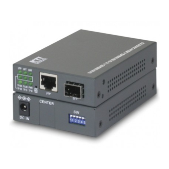
1.2 Product Panels The following figure illustrates the front panel and rear panel of the device: Front Rear 1.3 Specifications 10/100/1000 Twisted-pair Copper Port (UTP, RJ-45) Compliance IEEE 802.3 10Base-T, IEEE 802.3u 100Base-TX, IEEE 802.3u 1000Base-T Connectors Shielded RJ-45 jacks Pin assignments Auto MDI/MDI-X detection Configuration... - Page 10 LED Indicators Power status Local or remote TP indication on TP LEDs Loop-back test in-progress LED Loop-back test result LED FXLNK Fiber port link and activity status TP1G Twisted-pair copper port 1000Mbps and link status TP100 Twisted-pair copper port 100Mbps and link status TP10 Twisted-pair copper port 10Mbps and link status TPFDX...
- Page 11 Mechanical Dimension (base) 108 x 72.5 x 23 mm Housing Enclosed metal with no fan Mounting Desktop mounting, wall mounting, optional Din-rail mounting Environmental Operating Temperature Typical -40 C ~ +70 C (Main device) Storage Temperature C ~ +85 Relative Humidity 5% ~ 90% Electrical Approvals Part 15 rule Class A...
-
Page 12: Installation
2. Installation 2.1 Unpacking The product package contains: The media converter unit One product CD-ROM 2.2 Safety Cautions To reduce the risk of bodily injury, electrical shock, fire, and damage to the product, observe the following precautions. Do not service any product except as explained in your system documentation. -
Page 13: Mounting The Media Converter
2.3 Mounting the Media Converter The media converter can be mounted on a desktop or shelf or a wall. Make sure that there is proper heat dissipation from and adequate ventilation around the device. Do not place heavy objects on the device. - Page 14 Din-Rail mounting For a Din-Rail chassis, the device can support mounting on a Din-Rail. An optional Din-Rail bracket, KC-3DR can be purchased separately. The following figure shows an example after bracket installation: Center rack mounting The media converter can also be installed in KC-1300 center chassis. The center chassis provides the power supply to the converter also with optional power redundancy.
-
Page 15: Applying Power
2.4 Applying Power Before you begin the installation, check the AC voltage of your area. The AC power adapter which is used to supply the DC power for the unit should have the AC voltage matching the commercial power voltage in your area. Steps to apply the power to the device are: 1. -
Page 16: Making Utp Connections
2.5 Making UTP Connections The 10/100/1000 twisted-pair copper (TP) port supports the following connection types and distances: Network Cables 10BASE-T: 2-pair UTP Cat. 3,4,5 , EIA/TIA-568B 100-ohm 100BASE-TX: 2-pair UTP Cat. 5, EIA/TIA-568B 100-ohm 1000BASE-T: 4-pair UTP Cat. 5 or higher (Cat.5e is recommended), EIA/TIA-568B 100-ohm Link distance: Up to 100 meters Auto MDI/MDI-X Function This function allows the port to auto-detect the twisted-pair signals and adapts itself to form a valid... -
Page 17: Making Fiber Connection
2.6 Making Fiber Connection The mini-GBIC SFP (FX) port must be installed with an SFP fiber transceiver for making fiber connection. Your device unit may come with an SFP transceiver pre-installed when it was shipped. Installing SFP Fiber Transceiver To install an SFP fiber transceiver into mini-GBIC SFP port, the steps are: 1. -
Page 18: Loop-Back Test Push Button
2.7 Loop-back Test Push Button The push button is used to perform loop-back test between two media converters connected with fiber cable as shown below: It allows installer to perform diagnostic to the fiber link during installation and check the test result displayed on the LED indicators. -
Page 19: Configuration Dip Sw
2.8 Configuration DIP SW The configuration DIP SW (setting switches) is used for setting operation configuration manually. The functions of each DIP SW states are: SW1 SW2 SW3 SW4 SW5 SW6 Function OFF OFF OFF ------ ------ ------ Ignore DIP SW6 SW5 SW4 settings (Use software configuration for managed model) OFF OFF ------ ------ ------ Set TP Port in non-auto, 10Mbps, Full duplex mode... - Page 20 Function State Interpretation Power status The power is supplied to the unit. The power is not supplied to the unit. Local TP status Local TP port status displayed on TPxxx LEDs Remote TP port status displayed on TPxxx LEDs Blink Fail to display remote TP port status Remark: 1.
- Page 21 2.10 Configuring IP Address and Password for the Device For managed model, the device unit is shipped with the following factory default settings for software management: Default IP address of the device: 192.168.0.2 / 255.255.255.0 The IP Address is an identification of the device unit in a TCP/IP network. Each unit should be designated a new and unique IP address in the network.
-
Page 22: Functions
3. Functions To help a better understanding about the software management interfaces, this chapter describes some advanced functions provided by the media converter. 3.1 Abbreviation TP Port: The twisted-pair copper port of the media converter device. FX Port: The optical fiber port of the media converter device. Ingress Port: Ingress port is the input port on which a packet is received. -
Page 23: Converter Function
C-tag: Tag with TPID 0x8100 S-tag: Tag with TPID 0x88A8 Priority C-tagged frame: Priority tagged frame with C-tag (TPID=0x8100, VID=0) Priority S-tagged frame: Priority tagged frame with S-tag (TPID=0x88A8, VID=0) > VLAN C-tagged frame: Tagged frame with C-tag (TPID=0x8100, VID >... -
Page 24: Link Fault Pass Through Function
3.3 Link Fault Pass Through Function When the Link Fault Pass Through (LFPT) function is enabled and the media converter detects a link fault on one port segment, it will force the other port segment link down. It looks like that a link fault is passed from one port to the other. -
Page 25: Remote Tp Status Monitoring Function
3.4 Remote TP Status Monitoring Function The local media converter can monitor the TP port link status of its remote link partner connected on the fiber cable. The status is displayed on the local LED indicators as follows: Methods to enable the function Hardware setting: DIP SW5 is set to ON position Software setting:... -
Page 26: 802.1Q Control Function
3.5 802.1Q Control Function 802.1Q Control function allows perform 802.1Q VLAN related operation to the packets passing through the media converter according packet contents as follows: [Ingress Drop] setting The setting is the first filtering mechanism to filter incoming packets based on frame types. The options are: Disable - disable port ingress drop and admit all packet types... -
Page 27: Vlan Operation
Pop up 1 tag - remove up to 1 tag (outer tag if available) Pop up 2 tag - remove up to 2 tags (outer and inner tag if available) Egress Tagging – [Egress Tagging Rule] setting Tag is inserted into the outgoing frame in egress operation. Type 0 –... - Page 28 DEI= Frame outer tag – DEI TPID= Frame outer tag – TPID VID Filtering No filtering For untagged frames => No filtering For other types of frames => Filtering based on VID table configuration and the classified Tag – Note: [Management VLAN] –...
-
Page 29: Snmp Trap Function
3.6 SNMP Trap Function SNMP trap function allows the device to send trap message to an SNMP trap host over SNMP protocol when the associated trap event occurs. SNMP Trap settings The settings are used to configure a trap host who can receive the SNMP trap message issued from a media converter device unit. -
Page 30: Web Management
4. Web Management The media converter features an http server which can serve the management requests coming from any web browser software over TCP/IP network. Set IP Address for the System Unit Before the device unit can be managed from a web browser software, make sure a unique IP address is configured for the unit. -
Page 31: Main Management Menu
4.3 Main Management Menu The following information describes the basic functions of the main menu. Configuration System Device information, system and IP related settings Ports Port link status, operation mode configuration and other per port settings LLDP Settings for LLDP support Monitoring Statistics Overview List statistics for the local ports and remote TP port link status... - Page 32 Restore Default Command to restore the device unit with factory default settings Update Firmware Command to update the device’s firmware Configuration File Transfer Configuration file download & upload Logout Command to logout from current web management...
-
Page 33: Configuration
4.4 Configuration 4.4.1 System... - Page 34 Configuration Description MAC Address The MAC address factory configured for the switch. It can not be changed in any cases. S/W Version Firmware version currently running H/W Version Hardware version currently operating Active IP Address Current IP address for the switch management Active Subnet Mask Current subnet mask for IP address for the switch management Active Gateway...
- Page 35 Enable - A frame is discarded and counted as an excessive collision if 16 collisions occur for this frame. Disable – Not discarded BPDU_Transparent * Enable / disable BPDU & LLDP packet transparent forwarding [Apply] Click to apply the configuration change [Refresh] Click to refresh current configuration Note:...
-
Page 36: Management Vlan
4.4.1.1 Management VLAN Management VLAN settings allow administrator to access the device and perform the management over a dedicated VLAN. T he following rules are applied with the Management VLAN: 4 5 4 B If [Management VLAN] setting is VID=0, no limitation is applied in accessing the web 4 5 5 B 4 5 6 B management interface, but password authentication. -
Page 37: Ports
4.4.2 Ports Port Configuration Function Port TP - Twisted-Pair copper port (also specified Port #1 in other pages) FX - Fiber port (also specified Port #2 in other pages) Link Port link status Speed and duplex status with green background - port is link on Down with red background - port is link down Mode Select port operating mode... - Page 38 802.1Q Control Page when [802.1Q Filtering] function is disabled...
- Page 39 802.1Q Control Page when [802.1Q Filtering] function is enabled. The setting is “Allowed VID” or “Rejected VID” 802.1Q Control Function Default Tag – VID (PVID) Port VID, VID for Ingress Default Tag, also called “PVID” 1 ~ 4095 - decimal 12-bit VID value Default Tag - DEI CFI for Ingress Default Tag 0, 1 - 1-bit CFI value...
- Page 40 Pop up 1 tag – remove up to 1 tag (outer tag if available) Pop up 2 tag – remove up to 2 tags (outer and inner tag if available) Egress Tagging Rule Tag is inserted into the outgoing packet in egress operation. Type 0 –...
-
Page 41: 802.1Q Filtering
4.4.2.1 802.1Q Filtering Configuration Description VID TABLE Specify the characteristic of the VID table. Disable - set to disable 802.1Q filtering function. Allowed VID - the VID table specifies the allowed VIDs rejected VID - the VID table specifies the rejected VIDs * Both Allowed VID and rejected VID are used to “Enable”... - Page 42 When VID TABLE setting is changed from either “Allowed VID” or “Rejected VID” to “Disable”, the following message is also prompt for notices and confirmation. Notes: 1. VID table is referred for filtering VLAN-tagged frames according to the classified VID of each ingress frame.
-
Page 43: Lldp
4.4.3 LLDP Transmitted TLVs Description When checked the “port description” is included in LLDP information Port Description transmitted. When checked the “system name” is included in LLDP information System Name transmitted. When checked the “system description” is included in LLDP information System Description transmitted. - Page 44 each LLDP frame is determined by the Tx Interval value. Valid values: 5 – 32768 seconds Tx Hold Each LLDP frame contains information about how long the information in the LLDP frame shall be considered valid. The LLDP information valid period is set to Tx Hold multiplied by Tx Interval seconds.
-
Page 45: Monitoring
4.5 Monitoring 4.5.1 Statistics Overview Statistics Description Port TP - Twisted-Pair copper port on local unit FX - Fiber port on local unit Remote TP - TP port of the remote unit connected on the fiber link Link Port link status Speed and duplex status with green background - port is link on Down with red background - port is link down Tx Bytes... -
Page 46: Lldp Statistics
4.5.2 LLDP Statistics Counters Description Port The port on which LLDP frames are received or transmitted. (Port #1: TP port, Port #2: FX port) Tx Frames The number of LLDP frames transmitted on the port. Rx Frames The number of LLDP frames received on the port. Rx Error Frames The number of received LLDP frames containing error. -
Page 47: Lldp Table
4.5.3 LLDP Table Status Description Local Port The port on which the LLDP frame was received. (Port #1: TP port, Port #2: FX port) Chassis Id The Chassis Id is the identification of the neighbor's LLDP frames. Remote Port ID Port ID of the neighbor port System Name System Name advertised by the neighbor unit... -
Page 48: Ping
4.5.4 Ping Ping Description Target IP Address The target IP address to which the ping command issues Count The number of ping commands generated Time Out (in secs) The time out for a reply (in seconds) [Apply] Start the ping command Results Description Target IP Address... -
Page 49: Maintenance
4.6 Maintenance 4.6.1 Loop-back Test This menu is used to start a loop-back test operation with the link partner unit over the fiber link. The message displayed during test is: The result message displayed after a test finished is: The test result is also displayed on LEDs - LBT and LBR. 4.6.2 Reboot System This menu is used to reboot the device unit remotely with current configuration. -
Page 50: Restore Default
4.6.3 Restore Default This menu is used to restore all settings of the device unit with factory default values except current IP configuration and Management VLAN configuration. 4.6.4 Update Firmware This menu is used to perform in-band firmware (software) upgrade. Enter the path and file name of new firmware image file for uploading. -
Page 51: Configuration File Transfer
4.6.5 Configuration File Transfer This [download] command can be used to backup current device configuration and download it to the connected management PC. The default filename is “cfgdownload”. Configuration Description Filename Path and filename of a backup configuration file to be uploaded [Browse] Click to browse your computer file system for the configuration file [Upload]... -
Page 52: Snmp Support
5. SNMP Support S NMP version support Snmp v1, v2c management 1 2 3 0 B M anaged Objects MIB-II 1 2 3 1 B system OBJECT IDENTIFIER ::= { mib-2 1 } interfaces OBJECT IDENTIFIER ::= { mib-2 2 } OBJECT IDENTIFIER ::= { mib-2 4 } snmp OBJECT IDENTIFIER ::= { mib-2 11 }... -
Page 53: Appendix A. Factory Default Settings
Appendix A. Factory Default Settings System Configuration DHCP Enabled Disable Fallback IP Address 192.168.0.2 Fallback Subnet Mask 255.255.255.0 Fallback Gateway 0.0.0.0 Management VLAN Name Null Password Inactivity Timeout (secs) SNMP enabled Disable SNMP Trap destination 0.0.0.0 SNMP Read Community public SNMP Write Community private SNMP Trap Community... - Page 54 Egress Tagging Rule Type 0 Tagging Exceptional VID Egress Tag TPID 0x8100(c-tag) Custom TPID 0x8100 802.1Q Filtering VID TABLE Disable VID n (n=1-16) LLDP Configuration Transmitted TLVs Port Description Enable System Name Enable System Description Enable System Capabilities Enable Management Address Enable LLDP Parameters Tx Interval...
-
Page 55: Appendix B. Models & Optical Specifications
Appendix B. Models & Optical Specifications Model Definition KGC-310M-C Managed model with no pre-installed SFP transceiver KGC-310M-C-xxxx Managed model with pre-installed SFP transceiver SFP with 1000BASE-X fiber transceiver Model Ext. FiberCon. Reference Fiber Distance (Typ.) 1000M LC Duplex MMF 500m... - Page 56 -W3410S T1310/R1550 -9~ -3 -W4310S T1550/R1310 -9~ -3 Tx Power : Transmitter power (min. ~ max., unit: dBm) Rx Sen. : Receiver sensitivity (unit :dBm) Max.Rx. : Maximal Received power (unit : dBm) Note: The converter also can support typical 100M SFP transceivers.
Need help?
Do you have a question about the KGC-310M-C and is the answer not in the manual?
Questions and answers