
Related Manuals for KTI Networks KTGC-221


Summary of Contents for KTI Networks KTGC-221
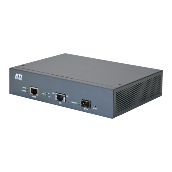
- Page 1 KTGC-221 Managed 10Gigabit Ethernet Media Converter Installation Guide DOC.200526A...
- Page 2 (C) 2020 KTI Networks Inc. All rights reserved. No part of this documentation may be reproduced in any form or by any means or used to make any directive work (such as translation or transformation) without permission from KTI Networks Inc.
- Page 3 The information contained in this document is subject to change without prior notice. Copyright (C) All Rights Reserved. TRADEMARKS Ethernet is a registered trademark of Xerox Corp. FCC WARNING AND NOTICE This equipment has been tested and found to comply with the limits for a Class A digital device, pursuant to Part 15 of the FCC Rules.
-
Page 4: Table Of Contents
Table of Contents 1. Introduction ..........................6 1.1 Features ......................6 1.2 Product Panels ....................7 1.3 Specifications ...................... 7 2. Installation ........................... 10 2.1 Unpacking ......................10 2.2 Safety Cautions ....................10 2.3 Mounting the Media Converter ................11 2.4 Applying Power .................... - Page 5 3.9 Reboot System ....................31 3.10 Restore Default ....................31 3.11 Update Firmware ..................... 31 3.12 Configuration File Transfer ................32 3.13 Logout ......................32 Appendix A. Factory Default Settings ..................33...
-
Page 6: Introduction
1. Introduction The device is a web smart 10Gigabit Ethernet media converter series which provide the following features: Data Conversion between different media types and speed rates The media converter supports the following conversions: 10Gbps (10GBASE-T) copper to/from 10Gbps (10GBASE-R) fiber ... -
Page 7: Product Panels
SNMP management support Digital Diagnostics Monitoring (DDM) function on fiber port IEEE 802.3az Energy Efficient Ethernet support (EEE) Supports desktop, wall, and Din-rail mounting Management functions Port configuration control and status monitoring In-band embedded firmware upgrade function ... - Page 8 Transmission rates 10Gbps, 5Gbps, 2.5Gbps, 1000Mbps Duplex support Full/Half duplex Network cable 10GBase-T Cat.6a UTP or better up to 100m 5GBase-T Cat.6 UTP or better up to 100m 2.5GBase-T Cat.5e UTP or better up to 100m 1000Base-T Cat.5 UTP or better up to 100m SFP+ Slot Compliance IEEE 802.3ae 10GBASE-R...
- Page 9 Housing Enclosed metal with no fan Mounting Desktop mounting, wall mounting, optional Din-rail mounting Environmental Operating Temperature Typical -40ºC ~ +55ºC Storage Temperature -40ºC ~ +85ºC Relative Humidity 10% ~ 90% Electrical Approvals Part 15 rule Class A EMC, CISPR32 Class A VCCI Class A Safety...
-
Page 10: Installation
2. Installation 2.1 Unpacking The product package contains: The device unit One AC power adapter QR code label linking to product documentation cloud 2.2 Safety Cautions To reduce the risk of bodily injury, electrical shock, fire and damage to the product, observe the following precautions. -
Page 11: Mounting The Media Converter
2.3 Mounting the Media Converter The device can be mounted on a desktop or shelf or a wall. Make sure that there is proper heat dissipation from and adequate ventilation around the device. Do not place heavy objects on the device. Wall mounting The device has one mounting wall on the bottom side to support wall mounting. -
Page 12: Applying Power
The following figure illustrates the converter is installed with Din-Rail mounting bracket: 2.4 Applying Power Device DC Input Jack Interface: DC Jack ( -D 6.3mm / + D 2.0mm) Operating input voltages: +12 ~ +48VDC Power consumption: 9W max. Polarity reversal: Shutdown protection Bundled AC Power Adapter Before you begin the installation, check the AC voltage of your area. -
Page 13: Making Rj-45 Copper Port Connection
2.5 Making RJ-45 Copper Port Connection The balanced twisted-pair copper (TP) port supports the following connection types and distances: Network Cables 10GBASE-T: 4-pair UTP Cat. 6a or better, EIA/TIA-568B 100-ohm 5GBAST-T: 4-pair UTP Cat. 6 or better, EIA/TIA-568B 100-ohm 2.5GBAST-T: 4-pair UTP Cat. - Page 14 2. Insert the SFP fiber transceiver into the SFP slot. Normally, a bail is provided for every SFP transceiver. Hold the bail and make insertion. 3. Until the SFP transceiver is seated securely in the slot, place the bail in lock position. Connecting Fiber Cables LC connectors are commonly equipped on most SFP transceiver modules.
-
Page 15: Optional 10G Sfp+ Transceivers
2.6.1 Optional 10G SFP+ Transceivers Part No. Wavelength Tx power Rx Sensitivity Fiber Connector Operating (dBm) (dBm) cable temperature support -10 ~ +70℃ SFP-10G-SR-A 850nm -7.1 ~ -1 -9.9 MMF * -10 ~ +70℃ SFP-10G-LR-A 1310nm -6 ~ 0.5 -14.4 SMF 10km ... - Page 16 Active Optical Cable (AOC) AOC is one of the forms of DAC cable. It integrates multimode optical fiber, fiber optic transceivers, and modules. AOCs have many benefits such as lighter weight, high performance, low power consumption, low interconnection loss, EMI immunity, and flexibility etc. Primarily, active optical cable (AOC) assemblies were invented to replace copper technology in data centers and high performance computing (HPC) applications.
-
Page 17: Making Management Connection
2.8 Making Management Connection The device is featured to support web-based management and SNMP management. Use Cat.5 cable and connect the management port to a TCP/IP network where the web management host and SNMP host are located. The following figure illustrates a typical connection: 2.9 RESET Button The button can also be used to restore the software configuration settings to factory default values. - Page 18 status Blink Data traffic activity LINK/ACT. SFP+ fiber port status The port link up The port link down. Blink The port link up and data traffic activity 10G/5G/2.5G Conversion line rate 5G/ON 10Gbps line rate indication 2.5G/ON 5G/ON 5Gbps line rate 2.5G/OFF 5G/OFF 2.5Gbps line rate...
-
Page 19: Configuring Ip Address And Password For The Device
2.11 Configuring IP Address and Password for the Device For managed model, the device unit is shipped with the following factory default settings for software management: Default IP address of the device: 192.168.0.2 / 255.255.255.0 Default Password of the device: 123 The IP Address is an identification of the device unit in a TCP/IP network. -
Page 20: Converter Function
2.12 Converter Function The device supports the following media conversions between fiber cable and Unshielded Twisted-pair (UTP) (copper) cable: Operation Rules: 1. Under “Auto” port configuration mode, the conversion line rate depends on the link speed finally established with the link partner on the RJ-45 copper port. Otherwise, a fixed line rate among 5Gbps, 2.5Gbps, and 1000Mbps is applied for the device. -
Page 21: Application
2.13 Application 2.14 SNMP Support The media converter is equipped with SNMP support. It can be managed from remote SNMP manager stations over SNMP protocol. SNMP version support SNMP v1, v2c management Managed Objects MIB-II system OBJECT IDENTIFIER ::= { mib-2 1 } interfaces OBJECT IDENTIFIER ::= { mib-2 2 } OBJECT IDENTIFIER ::= { mib-2 4 }... - Page 22 SNMP Settings The following settings on web management UI are used to configure SNMP function and SNMP trap function. [SNNP] Enable / disable SNMP function [SNNP Trap destination] The IP address of the target SNMP trap host who is allowed to receive the traps [SNMP Read community] The community allowed for the SNMP [get] message [SNMP Write community]...
-
Page 23: Web Management
3. Web Management The media converter features an http server which can serve the management requests coming from any web browser software over TCP/IP network. Web Browser Compatible web browser software with JAVA script support Microsoft Internet Explorer 4.0 or later Set IP Address for the System Unit Before the device unit can be managed from web browser software, make sure a unique IP address is configured for the unit. -
Page 24: Main Management Menu
The device will accept only one successful management connection at the same time. The other connection attempts will be prompted with a warning message. A new connection will be accepted when the current user logout successfully or auto logout by the device due to no access for time out of 3 minutes. -
Page 25: System
Maintenance Reboot System Command to reboot the device unit Restore Default Command to restore the device unit with factory default settings Update Firmware Command to update the device firmware Configuration File Command to transfer (upload/download) configuration file Transfer Logout Command to logout from current web management 3.4 System -25-... - Page 26 Configuration Description MAC Address The MAC address factory configured for the switch It can not be changed in any cases. S/W Version The firmware version currently running H/W Version The hardware version currently operating Active IP Address Currently used IP address for the switch management Active Subnet Mask Currently used subnet mask for IP address for the switch management Active Gateway...
-
Page 27: Ports
3.5 Ports Port Configuration Function Enable EEE Mode Check to enable EEE function. MNGT – Management port Port UTP – RJ-45 copper port SFP+ - Fiber port Link Port link status Line rate and Speed/duplex status with green background - port is link on Down with red background - port is link down Mode Select MNGT port operating mode... -
Page 28: Statistics Overview
2.5Gbps, 1Gbps. (10Gbps: 10GBASE-T to 10GBASE-R) 5Gbps (5GBASE-T to 5GBASE-R) 2.5G 2.5Gbps (2.5GBASE-T to 2500BASE-X) 1000Mbps (1000BASE-T to 1000BASE-X auto-negotiation disabled) Disabled Disable the conversion Apply Click to apply the changes. Refresh Click to refresh the page. Any changes made locally will be undone. 3.6 Statistics Overview Configuration Description... -
Page 29: Sfp Ddm
3.7 SFP DDM Status Description SFP Ports Port numbers which are equipped with SFP slot. Identifier Identification information of the transceiver Connector The connector type used on the transceiver SONET Compliance The SONET compliance information of the transceiver Ethernet Compliance Ethernet compliance information of the transceiver Vendor Name The vendor name of the transceiver... -
Page 30: Ping
3.8 Ping Ping Description Target IP Address The target IP address to which the ping command issues Count The number of ping commands generated Time Out (in secs) The time out for a reply (in seconds) Apply Start the ping command Results Description Target IP Address... -
Page 31: Reboot System
3.9 Reboot System This menu is used to reboot the device remotely with current configuration. Starting this menu will make your current http connection lost. You must rebuild the connection to perform any management operation to the unit. 3.10 Restore Default This menu is used to restore all settings of the device unit with factory default values. -
Page 32: Configuration File Transfer
3.12 Configuration File Transfer This [download] command can be used to backup current switch configuration and download it to the connected management PC using default filename, switch.cfg. Configuration Description Filename Path and filename of a backup configuration file to be uploaded Browse Click to browse your computer file system for the configuration file Upload... -
Page 33: Appendix A. Factory Default Settings
Appendix A. Factory Default Settings System Configuration DHCP Enabled Not select (disabled) Fallback IP Address 192.168.0.2 Fallback IP Subnet mask 255.255.255.0 Fallback Gateway IP 192.168.0.1 Name Null Password Inactivity Timeout (secs) SNMP enabled Not select (disabled) SNMP Trap destination 0.0.0.0 SNMP Read community public SNMP Write community...
Need help?
Do you have a question about the KTGC-221 and is the answer not in the manual?
Questions and answers