
Related Manuals for KTI Networks KFC-241


Summary of Contents for KTI Networks KFC-241
- Page 1 KFC-241 Industrial 10/100BASE-T to 100BASE-FX Media Converters Installation Guide DOC.110516...
- Page 2 (C) 2011 KTI Networks Inc. All rights reserved. No part of this documentation may be reproduced in any form or by any means or used to make any directive work (such as translation or transformation) without permission from KTI Networks Inc.
- Page 3 The information contained in this document is subject to change without prior notice. Copyright (C) All Rights Reserved. TRADEMARKS Ethernet is a registered trademark of Xerox Corp. FCC NOTICE This device complies with Part 15 of the FCC Rules. Operation is subject to the following two conditions: (1) This device may not cause harmful interference, and (2) This device must accept any interference received, including the interference that may cause undesired operation.
-
Page 4: Table Of Contents
Table of Contents 1. Introduction..............................5 1.1 Features ..........................6 1.2 Specifications ......................... 7 1.3 Model Specifications ......................11 1.4 Special Functions......................... 11 2. Installation..............................13 2.1 Unpacking ..........................13 2.2 Safety Cautions........................13 2.3 DIN-Rail Mounting........................ 14 2.4 Mounting on a Plane Surface....................18 2.5 Applying Power ........................ -
Page 5: Introduction
1. Introduction The industrial 10/100BASE-TX to 100BASE-FX media converter series provides industrial strength Ethernet copper-to-fiber media conversion, allowing for 10Base-T-100Base-FX or 100Base-TX-100Base-FX over multi-mode or optional single-mode fiber optical media. In addition to the basic media conversion functions, the converters also provide some special functions to enhance the flexibility for wide application needs as follows: AUTO-NEGO FUNCTION The copper port is featured this function which performs a negotiation process for the speed and duplex... -
Page 6: Features
operate at different speed, but switches to direct conversion automatically and with the least latency when both media ends operate at the same speed. LINK FAULT PASS THROUGH FUNCTION The function allows the link fault status passes through from one media end to another media end transparently. INDUSTRIAL ENHANCEMENT For industrial environment, the converters are designed with the following enhanced features exceeding that of commercial media converters:... -
Page 7: Specifications
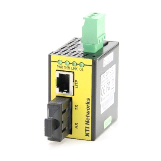
1.2 Specifications This figure shows the important components of the converters: Model KFC-241-L Model KFC-241-H... - Page 8 Supported Link Distance MMF up to 2km SMF, single SMF (model dependent) Eye Safety compliance IEC825 Class 1 DC Power Input KFC-241-L Interfaces Screw-type Terminal Block 3P (TB-3P) DC Jack (-D 6.3mm /+D 2.0mm) Operating Input Voltages +4.5VDC ~ +50VDC...
- Page 9 Power status LINK Link status 100M Copper port operating speed Fiber port optical link Mechanical Dimension (base) KFC-241-L W 34mm x D 49mm x H 56mm KFC-241-H - W 45.5mm x D 49mm x H 56mm Weight KFC-241-L 132g KFC-241-H...
- Page 10 EN 50081-1: EN55022 CISPR Class B EN61000-3-2 Device <75W EN61000-3-3 Clause 5 EN 55024 Severity Level IEC 61000-4-2 ESD Test Contact +/-6KV/Air +/-8KV IEC 61000-4-3 RS Test Power/Data Ports Level 1, 2, 3 IEC 61000-4-4 EFT/Burst Test DC IN +/-1KV/Data Ports +/-0.5KV IEC 61000-4-5 Surge Test DC IN +/-0.5KV/Data Ports +/-1KV...
-
Page 11: Model Specifications
1.3 Model Specifications The media converter series provides the following fiber options: Model Ext. Connector Wavelength Fiber Distance Tx power Sensitivity Rx Power max. Duplex ST 1310nm MMF 2km -20 ~ -14 -32 max. -8 min. Duplex SC 1310nm MMF 2km -20 ~ -14 -31 max. - Page 12 Link Fault Pass Through Function When this function is enabled, a link fault detected on the TP copper port will force a link down on the FX fiber port and vice versa. Similarly, a link fault detected on the FX fiber port will also force a link down on the TP copper port.
-
Page 13: Installation
2. Installation 2.1 Unpacking Check that the following components have been included: Information CD The Media Converter unit DIN-rail mounting bracket (It may have been pre-installed on the device unit.) The following are available optional accessories: Plane Mounting Bracket: The bracket is used for mounting the converter on a plane surface. Commercial-rated AC power adapters: The adapters are used for supplying DC power to the converter via DC power jack interface. -
Page 14: Din-Rail Mounting
The steps to mount the converter onto a DIN-rail are: 1. Install the mounting bracket onto the device unit as shown below: Model: KFC-241-L Model: KFC-241-H 2. Attach bracket to the lower edge of the DIN rail and push the unit upward a little bit until the bracket can clamp on the upper edge of the DIN rail. - Page 15 3. Clamp the unit to the DIN rail and make sure it is mounted securely. Model: KFC-241-L Model: KFC-241-H 4. Make sure that there is proper heat dissipation from and adequate ventilation around the device. -15-...
- Page 16 The final mechanical dimensions after installing DIN-Rail mounting bracket are: Model: KFC-241-L with DIN-Rail mounting bracket -16-...
- Page 17 Model: KFC-241-H with DIN-Rail mounting bracket -17-...
-
Page 18: Mounting On A Plane Surface
Screw the bracket and install it on the converters. Model: KFC-241-H Model: KFC-241-L Make sure that there are proper heat dissipation from and adequate ventilation around the device. Do not place heavy objects on the device. - Page 19 The final mechanical dimensions after installing panel mounting bracket are: Model: KFC-241-L with panel mounting bracket -19-...
- Page 20 Model: KFC-241-H with panel mounting bracket -20-...
-
Page 21: Applying Power
2.5 Applying Power The converters provide two types of power interfaces, terminal block and DC power jack for receiving DC power input from external power supply. KFC-241-L KFC-241-H DC IN Terminal Block (TB-3P) Connector Screw-type Terminal Block 3P Contacts DC IN Positive (+) terminal... -
Page 22: Making Copper Port Connection
DC IN Specification Model KFC-241-L KFC-241-H Connectors TB-3P, DC Jack TB-3P Voltage Range +4.5 ~ +50VDC +110VDC Power Consumption 1.6W@+7.5V 2.9W@110V 1.6W@+12V 2W@+48V 2.6 Making Copper Port Connection The copper port is featured to support connection to : Auto-negotiation devices... -
Page 23: Making Fiber Port Connection
2.7 Making Fiber Port Connection The fiber port operates on 100Mbps and full duplex. A variety of fiber options is provided as follows: Model Optical Specifications Model Ext. Connector Wavelength Fiber Distance Tx power Sensitivity Rx Power max. Duplex ST 1310nm MMF 2km -20 ~ -14 -32 max. -
Page 24: Led Indicators
3. LED Indicators The following figure shows the locations of LED indicators: 3.1 States and Indications Display State Interpretation Power status Power on Power off 100M TP port speed status Copper port operates in 100Mbps 10Mbps LINK Port link status Link up and no traffic Link fault Blink... -
Page 25: Appendix. On-Board Configuration
Appendix. On-board Configuration Six configuration jumpers are provided on the internal PC board of the device. They can be used to change the configuration and adapt the device for some special applications. The jumpers are inaccessible by users. Jumper Settings TP auto mode Auto-negotiation (factory default) Forced mode...
Need help?
Do you have a question about the KFC-241 and is the answer not in the manual?
Questions and answers