
Related Manuals for KTI Networks KGC-301/C


Summary of Contents for KTI Networks KGC-301/C
- Page 1 CC-Link IE TSN Certified 10/100/1000BASE-T to 100/1000BASE-X Media Converter KGC-301/C Installation Guide DOC.241022...
- Page 2 (C) 2024 KTI Networks Inc. All rights reserved. No part of this documentation may be reproduced in any form or by any means or used to make any directive work (such as translation or transformation) without permission from KTI Networks Inc.
-
Page 3: Fcc Notice
The information contained in this document is subject to change without prior notice. Copyright (C) All Rights Reserved. TRADEMARKS Ethernet is a registered trademark of Xerox Corp. FCC NOTICE This device complies with Part 15 of the FCC Rules. Operation is subject to the following two conditions: (1) This device may not cause harmful interference, and (2) This device must accept any interference received, including the interference that may cause undesired operation. -
Page 4: Table Of Contents
Table of Contents 1. Introduction ........................... 5 1.1 Features ......................6 1.2 Product Panels ....................6 1.3 Specifications ...................... 6 2. Installation ............................. 9 2.1 Unpacking ......................9 2.2 Safety Cautions ....................9 2.3 Mounting the Media Converter ................10 2.4 Applying Power .................... -
Page 5: Introduction
1. Introduction The KGC-301/C is a CC-Link IE TSN Certified Gigabit Ethernet media converter series that provides the following features: Data Conversion between different Media types and Speed The media converter supports the following conversions: 1000Mbps (1000BASE-T) copper to/from 1000Mbps (1000BASE-X) fiber ... -
Page 6: Features
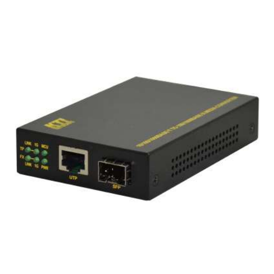
1.1 Features Basic functions Tri-speed 10/100/1000Mbps copper to dual-speed 1G/100Mbps fiber conversion Support full wire speed conversion Support jumbo frame conversion Provide direct conversion with shortest latency between two links at same line rate Support transparent conversion of any packet types with no packet modification ... - Page 7 Duplex support Full/Half duplex Network cable Cat.5 UTP SFP - Dual-speed Fiber Port Compliance IEEE 802.3z 1000Base-X, IEEE 802.3u 100BASE-FX Connectors SFP for optional SFP type fiber transceivers Configuration Auto speed detection, Fixed on auto-negotiation 1000Mbps Full duplex Transmission rate 1000Mbps, 100Mbps (Dual-speed support) Network cables MMF 50/125m 62.5/125m, SMF 9/125m...
- Page 8 DC IN - DC Power Input Screwed terminal block: & contacts Interfaces DC Jack ( -D 6.3mm / + D 2.0mm) Operating Input Voltages +12 ~ +60VDC Power consumption 2.4W max. @60V Mechanical Dimension (base) 108 x 72.5 x 23mm Housing Enclosed metal with no fan Mounting...
-
Page 9: Installation
2. Installation 2.1 Unpacking The product package contains: The device unit QR code label linking to product documentation cloud 2.2 Safety Cautions To reduce the risk of bodily injury, electrical shock, fire and damage to the product, observe the following precautions. -
Page 10: Mounting The Media Converter
2.3 Mounting the Media Converter The media converter can be mounted on a desktop or shelf or a wall. Make sure that there is proper heat dissipation from and adequate ventilation around the device. Do not place heavy objects on the device. -
Page 11: Applying Power
Din-Rail mounting For a Din-Rail chassis, the device can support mounting on a Din-Rail. The following figure shows an example after bracket installation: 1. Install the mounting bracket onto the back of the device with screws as shown below: 2. Attach bracket to the lower edge of the DIN rail and push the unit upward a little bit until the bracket can clamp on the upper edge of the DIN rail. -
Page 12: Dc Power Jack
DC Power input contacts: - DC-Negative (-) input terminal + DC+Negative (+) input terminal Terminal Plug: A 2P flange terminal plug Power wires: 24 ~ 12AWG (IEC 0.5~2.5mm2) Wire length: 1 meter max. VDC input rating: +12V ~ +60V 2.4.2 DC Power Jack Contact Connector: DC Jack (-Ø... -
Page 13: Making Utp Connections
2.5 Making UTP Connections The 10/100/1000 twisted-pair copper port supports the following connection types and distances: Network Cables 10BASE-T: 2-pair UTP Cat. 3,4,5 , EIA/TIA-568B 100-ohm 100BASE-TX: 2-pair UTP Cat. 5, EIA/TIA-568B 100-ohm 1000BASE-T: 4-pair UTP Cat. 5 or higher (Cat.5e is recommended), EIA/TIA-568B 100-ohm Link distance: Up to 100 meters Auto MDI/MDI-X Function This function allows the port to auto-detect the twisted-pair signals and adapts itself to form a valid... -
Page 14: Making Fiber Connection
2.6 Making Fiber Connection The mini-GBIC SFP port must be installed with an SFP fiber transceiver for making fiber connection. Your device may come with an SFP transceiver pre-installed when it was shipped. Installing SFP Fiber Transceiver To install an SFP fiber transceiver into the SFP port, the steps are: 1. -
Page 15: Sfp Configuration Dip Switch (Sw4)
2.6.1 SFP Configuration DIP Switch (SW4) Mode 1000Mbps, Full duplex, Auto-negotiation enabled (Factory default) Auto detection Full duplex Line rate, 1000Mbps or 100Mbps is determined by detecting the data rate information embedded in the installed SFP transceiver Note: The setting change of SW4 takes effect after next device power-up. 2.7 LED Indication State Interpretation... -
Page 16: Media Converter Functions
3 Media Converter Functions 3.1 Line Rate Conversion The device supports the following data conversions between fiber cable and twisted-pair Cat.5 (copper) cable: The data line rate on twisted-pair copper segment depends on the link speed finally established with the link partner. However, the line rate can be fixed at one specific line rate by setting UTP configuration DIP switches (SW1 ~ SW3). -
Page 17: Link Fault Pass Through Function
3.3 Link Fault Pass Through Function When the Link Fault Pass Through (LFPT) function is enabled. When the media converter detects a link fault on one port segment, it will force the other port segment link down. It looks like that a link fault is passed from one port to the other. -
Page 18: Lfpt Configuration Dip Switch (Sw5)
3.3.1 LFPT Configuration DIP Switch (SW5) The LFPT function can be enabled by setting SW5 as below: LFPT Disabled (Factory default) Enabled Note: The setting change of SW5 takes effect after next device power-up. Under certain condition, LFPT function is not supported. See the following table: SFP Port Mode LFPT Function 1000Mbps, Full duplex,... -
Page 19: Appendix A. Models & Optical Specifications
Appendix A. Models & Optical Specifications Model Definition KGC-301/C Managed model with no pre-installed SFP transceiver KGC-301/C -xxxx Managed model with pre-installed SFP transceiver SFP with 1000BASE-X fiber transceiver Model Ext. FiberCon. Reference Fiber Distance (Typ.) 1000M LC Duplex MMF 500m... - Page 20 Optical 1000BASE-X Specifications Model Ext. Wavelength Tx Power* Rx Sen.* Max.Rx* 850nm -9.5~ -4 1310nm -9.5~ -3 -LX20 1310nm -8~ -2 -LX30 1310nm -4~ +1 -LX50 1550nm -4~ +1 -LX70 1550nm 0~ +5 Bi-Direction WDM over single SMF -W3510 T1310/R1550 -9~ -3 -W5310 T1550/R1310...
Need help?
Do you have a question about the KGC-301/C and is the answer not in the manual?
Questions and answers