Table of Contents
Advertisement
Quick Links
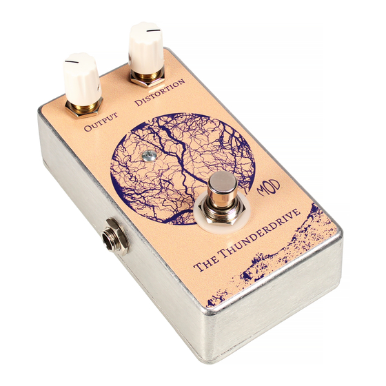
THE THUNDERDRIVE (K-950)
OUTPUT
DISTORTION
Unplug when not in use
to save battery life.
The Thunderdrive
TO
FROM
AMP
GUITAR
IN
OUT
Modkitsdiy.com
Use these instructions to learn:
How to build an effects pedal for overdrive.
The Thunderdrive is an overdrive pedal kit that will provide a strong clean signal boost in the early gain
settings and smooth distortion at maximum gain settings. Adjusting output and distortion controls provides
a wide variety of tones in spite of its simple construction. It is capable of overdriving the preamp section of
your guitar amp or adding its own layer of distortion at lower volume.
www.modkitsdiy.com
1
Copyright © 2011 by modkitsdiy.com
Advertisement
Table of Contents

Related Manuals for Mod THUNDERDRIVE (K-950)


Summary of Contents for Mod THUNDERDRIVE (K-950)
- Page 1 THE THUNDERDRIVE (K-950) OUTPUT DISTORTION Unplug when not in use to save battery life. The Thunderdrive FROM GUITAR Modkitsdiy.com Use these instructions to learn: How to build an effects pedal for overdrive. The Thunderdrive is an overdrive pedal kit that will provide a strong clean signal boost in the early gain settings and smooth distortion at maximum gain settings.
-
Page 2: Table Of Contents
TABLE OF CONTENTS TOOL LIST …………………………………………………………………………...2 PARTS LIST DRAWINGS………………………………………………………….3, 4 SOLDERING TIPS …………………………………………………………………...5 STEP BY STEP ASSEMBLY INSTRUCTIONS …………………………………...6 Section 1 – Mount ¼” Jacks and Terminal Strip Components ……………...6 Section 2 – Mount Potentiometers and Footswitch ………………………...7 Section 3 – Mount and Connect Remaining Components ………..…………..7 Section 4 –... -
Page 3: Parts List Drawings
PARTS LIST 1 Stranded Wire (22 AWG) - Blue DPDT Foot Switch S-W22BL (3 FT) P-H498 Enclosure P-H1590BCE 250k Potentiometer (Audio Taper) R-VBM-250KA-SS Knob (Scalloped Edge) P-K801 Terminal Strip with 5 Terminals Battery Clip P-0501H01 S-H155 #4 Screw (3/8" long) S-HS440-38 ¼”... - Page 4 PARTS LIST 2 NPN BJT (MPSA18) 4.7k Resistor ½ W P-QMPSA18 R-A4D7K 4.7K yellow violet gold E B C 1N4148 HIGH SPEED SOLID STATE DIODE 2M Resistor ½ W P-Q971 R-A2M black green gold 0.1 F Capacitor 50V C-PFD1-50-R 104J Insulating Tolex (Use to insulate the battery from the footswitch lugs) S-G312...
-
Page 5: Soldering Tips
SOLDERING TIPS It is important to make a good solder joint at each connection point. A cold solder joint is a connection that may look connected but is actually disconnected or intermittently connected. (A cold solder joint can keep your project from working.) Follow these tips to make a good solder joint. -
Page 6: Step By Step Assembly Instructions
SECTION 1 – Mount ¼” Jacks and Terminal Strip Components Please refer to DRAWING 1 and DRAWING 2. Orient the box with ½” hole nearest you. Input Jack Mount input jack in 3/8" hole on left side of box with hardware provided. RING LUG Washer goes under nut on outside of box. -
Page 7: Section 2 - Mount Potentiometers And Footswitch
SECTION 2 – Mount Potentiometers and Footswitch Please refer to DRAWING 3. 1) Mount the two 250K potentiometers in the 3/8" holes at the top of the enclosure using hardware provided. Before mounting, gently bend the pot lugs back so Remove nut and flat washer from potentiometers and they are pointing straight up when mounted. - Page 8 DRAWING 1 INSIDE VIEW OF THE ENCLOSURE 1/8" 3/8" 3/8" 1/2" DRAWING 2 INPUT JACK OUTPUT JACK...
- Page 9 DRAWING 3 INPUT JACK OUTPUT JACK DRAWING 4 DISTORTION OUTPUT INPUT JACK OUTPUT JACK Place the insulating tolex between the battery and footswitch lugs “3” and “6” to prevent shorting the signal to ground through the battery case in bypass. 1 ¾”...
Need help?
Do you have a question about the THUNDERDRIVE (K-950) and is the answer not in the manual?
Questions and answers