Table of Contents
Advertisement
Quick Links
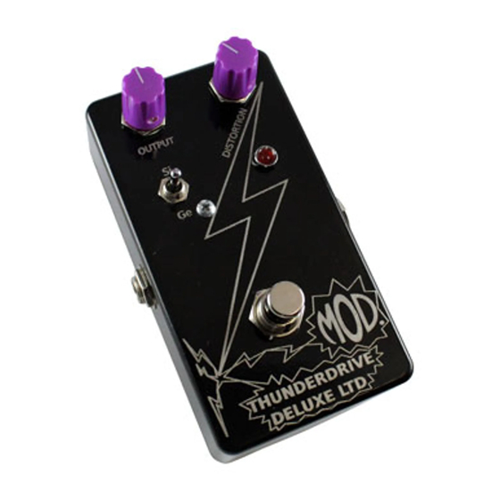
THE THUNDERDRIVE DELUXE LTD (K-956)
DIODE SWITCH
Signal Output
(To Amplifier)
Use these instructions to learn:
How to build an effects pedal for overdrive.
The Thunderdrive Deluxe LTD is an overdrive pedal kit that will provide a strong clean signal boost in the
early gain settings and smooth distortion at maximum gain settings. Adjusting output and distortion controls
provides a wide variety of tones in spite of its simple construction. It is capable of overdriving the preamp
section of your guitar amp or adding its own layer of distortion at lower volume. This version is equipped
with a three position diode selector switch.
The switch offers three different settings and tones. The top position is the classic silicon clipping diodes
used in the original Thunderdrive. The middle position gives you the lifted diode "turbo" sound from the
Deluxe model. The bottom position is a new setting limited to this version using germanium diodes for a
warm vintage distortion.
Warning: This circuit was designed for use with a 9 VDC power supply only.
OUTPUT
DISTORTION
LED
(From Guitar)
Unplug when not in use
to save battery life.
1
Copyright © 2019 by modkitsdiy.com
Signal Input
Advertisement
Table of Contents

Related Manuals for Mod THUNDERDRIVE DELUXE LTD


Summary of Contents for Mod THUNDERDRIVE DELUXE LTD
- Page 1 How to build an effects pedal for overdrive. The Thunderdrive Deluxe LTD is an overdrive pedal kit that will provide a strong clean signal boost in the early gain settings and smooth distortion at maximum gain settings. Adjusting output and distortion controls provides a wide variety of tones in spite of its simple construction.
-
Page 2: Table Of Contents
TABLE OF CONTENTS TOOL LIST …………………………………………………………………………...2 PARTS LIST DRAWINGS………………………………………………………….3, 4 SOLDERING TIPS …………………………………………………………………...5 STEP BY STEP ASSEMBLY INSTRUCTIONS …………………………………...6 Section 1 – Mount LED, ¼” Jacks and Terminal Strip Components ………..6 Section 2 – Mount Potentiometers, Footswitch and Toggle Switch ………..7 Section 3 –... -
Page 3: Parts List Drawings
PARTS LIST 1 Stranded Wire (22 AWG) - Red 3PDT Foot Switch K-PUL1569 (3 FT) P-H501 Enclosure P-H1590BCE-BK 250kΩ Potentiometer (Audio Taper) R-VBM-250KA-SS Knob (Scalloped Edge) P-K801P Terminal Strip with 5 Terminals Battery Clip P-0501H01 S-H155 #4 Screw (3/8" long) S-HS440-38 ¼”... - Page 4 PARTS LIST 2 NPN BJT (2N5088) 820Ω Resistor ½ W P-Q2N5088 R-A820 5088 gray brown gold E B C 1N4148 HIGH SPEED SOLID STATE DIODE 4.7kΩ Resistor ½ W P-Q971 R-A4D7K 4.7K yellow violet gold Germanium Diode (1N34A) P-Q972 2MΩ Resistor ½ W R-A2M black green...
-
Page 5: Soldering Tips
SOLDERING TIPS It is important to make a good solder joint at each connection point. A cold solder joint is a connection that may look connected but is actually disconnected or intermittently connected. (A cold solder joint can keep your project from working.) Follow these tips to make a good solder joint. -
Page 6: Step By Step Assembly Instructions
SECTION 1 – Mount LED, ¼” Jacks and Terminal Strip Components Please refer to DRAWING 1 and DRAWING 2. Orient the box with the ½” hole nearest you. 1) Mount the LED in the ¼” hole below the distortion pot’s The Anode (+) side of the LED is mounting hole. -
Page 7: Section 2 - Mount Potentiometers, Footswitch And Toggle Switch
SECTION 2 – Mount Potentiometers, Footswitch and Toggle Switch Please refer to DRAWING 3 & DRAWING 4. 1) Mount the two 250K potentiometers in the 3/8" holes at the top of the enclosure using the hardware provided. Before mounting, gently Remove nut and flat washer from potentiometers and bend the pot lugs back so they are pointing straight... -
Page 8: Section 3 - Mount And Connect Remaining Components
SECTION 3 – Mount and Connect Remaining Components Please refer to DRAWING 4. 1) Connect one of the 0.1µF capacitors with one lead at terminal #5 of the terminal strip and the other lead to output pot lug “1”. 2) Connect the other 0.1µF capacitor to terminal #4 and to both lugs “2” and “3” of the distortion pot. Solder all connections at terminals #3, #4 and distortion pot lugs “2”... -
Page 9: Assembly Drawings (4 Drawings)
DRAWING 1 3/8" 3/8" 1/4" 1/4" 1/8" 3/8" 3/8" 1/2" DRAWING 2 DISTORTION POT HOLE INPUT JACK OUTPUT JACK... - Page 10 DRAWING 3 DISTORTION OUTPUT INPUT JACK OUTPUT JACK DRAWING 4 DISTORTION OUTPUT INPUT JACK OUTPUT JACK P-H501...
- Page 11 OUTPUT 2N5088 Input .1µ 250KA DISTORTION Output 2N5088 3PDT Foot Switch NPN BJT Collector Base Copyright © 2019 by modkitsdiy.com Emitter Switching function of the 3PDT switch. The solid line “Thunderdrive Deluxe LTD” illustrates an internal connection between terminals. Schematic...
Need help?
Do you have a question about the THUNDERDRIVE DELUXE LTD and is the answer not in the manual?
Questions and answers