Table of Contents
Advertisement
DWELL
TO
AMP
IN
Use these instructions to learn:
How to build an effects pedal for reverb.
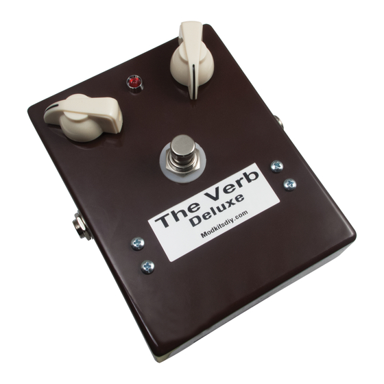
This pedal produces sweet warm reverb using the Belton Digi-Log module. It operates on a 9V battery or
AC adapter (center negative), which are not included. When completed this pedal draws considerable
current and battery life will be short. The use of an AC adapter is highly recommended. This effect works
best when placed at the end of your effects chain.
Warning: This circuit was designed for use with a 9 VDC power supply only.
THE VERB DELUXE (K-915)
Deluxe
Reverb
Modkitsdiy.com
1
Copyright © 2014 by modkitsdiy.com
LED
MIX
Unplug when not in use
to save battery life.
FROM
GUITAR
OUT
9 VDC
FROM
CENTER (-)
ADAPTER
Advertisement
Table of Contents

Related Manuals for Mod The Verb Deluxe


Summary of Contents for Mod The Verb Deluxe
- Page 1 THE VERB DELUXE (K-915) DWELL Unplug when not in use to save battery life. FROM GUITAR Deluxe Reverb Modkitsdiy.com 9 VDC FROM CENTER (-) ADAPTER Use these instructions to learn: How to build an effects pedal for reverb. This pedal produces sweet warm reverb using the Belton Digi-Log module. It operates on a 9V battery or AC adapter (center negative), which are not included.
-
Page 2: Table Of Contents
TABLE OF CONTENTS TOOL LIST …………………………………………………………………………...2 PARTS LIST DRAWINGS………………………………………………………….3, 4 FINAL ASSEMBLY REFERENCE DRAWING………………………………………5 SOLDERING TIPS …………………………………………………………………...6 STEP BY STEP ASSEMBLY INSTRUCTIONS ………………………………7 - 11 Section 1 – Mount Large Components …………………………………...7 Section 2 – Prepare BTDR Reverb Module …………………………………...8 Section 3 –... -
Page 3: Parts List Drawings
PARTS LIST 1 Stranded Wire (22 AWG) - Red DPDT Foot Switch K-PUL1569 (6.5 FT) P-H498 Enclosure P-H1590BBCE-BN Reverb Module P-RBTDR-2H-L accutronics ® Model: BTDR-2H 6 5 4 3 2 1 Chicken Head Knob P-K300C Potentiometers with Linear Taper R-V38-100KL R-V38-500KL Battery Clip S-H155... - Page 4 PARTS LIST 2 DC Power Jack 1kΩ Resistor ½ W 1.5kΩ Resistor ½ W S-H750 R-A1K R-A1D5K 1.5K brown brown black green gold gold Double Sided Foam Tape (1" x 1") 4.7kΩ Resistor ½ W 6.8kΩ Resistor ½ W R-A4D7K R-A6D8K 6.8K 4.7K...
-
Page 5: Final Assembly Reference Drawing
FINAL ASSEMBLY REFERENCE DRAWING This is a large version of the final assembly drawing. Refer to this drawing as you make your way through each step of the instructions. Before you make a new connection at a particular terminal or solder lug, notice how many other connections will be made at that terminal. That way you can decide whether it’s best for you to solder the connection and leave space open for future connections or hold off on soldering until after every connection at that location has been made. -
Page 6: Soldering Tips
SOLDERING TIPS It is important to make a good solder joint at each connection point. A cold solder joint is a connection that may look connected but is actually disconnected or intermittently connected. (A cold solder joint can keep your project from working.) Follow these tips to make a good solder joint. -
Page 7: Step By Step Assembly Instructions
SECTION 1 – Mount Large Components The Verb Deluxe enclosure has a high gloss finish. To avoid scratching the surface while assembling this kit, you may want to place a soft cloth, towel or similar item over your work surface. -
Page 8: Section 2 - Prepare Btdr Reverb Module
SECTION 2 – Prepare BTDR Reverb Module Pin 4 will not be used. Strip a 3/8" piece of insulation from the wire provided accutronics ® to use as an insulating sleeve for pin 4. Gently press this piece of insulation over pin 4 of the reverb module. -
Page 9: Section 4 - Mount Components To Terminal Strips
Strip and tin a 2 ½” piece of wire and connect to terminals #11 and #16. Connect via the lower terminal holes to leave more room for mounting the terminal strip components. Do not solder at terminal #16, yet. Strip and tin a 2" piece of wire and connect to 100KL pot lug 2 and terminal #5. Strip and tin a 2 ½”... -
Page 10: Section 5 - Install Reverb Module
Connect the 6.8K resistor to terminals #4 and #22. (Make sure to leave room at both terminals for mounting other components). Connect the 78L05 to terminals #17, #20 and #22: 78L05 “Out” lead connects to #17 “Gnd” lead connects to #20 “In”... -
Page 11: Section 6 - Finishing Up
Unplug from the input jack of the unit to turn it off and save power. Warning: The Verb Deluxe does not hold back on reverberation potential. At maximum dwell and mix settings you may be overtaken by a virtual tidal wave of sonic reflections. -
Page 12: Assembly Drawings (6 Drawings)
DRAWING 1 3/8" 3/8" 1/4" INSIDE VIEW OF THE ENCLOSURE 3/8" 3/8" 15/32" 1/8" 1/8" 1/8" 1/8" 15/32" BOTTOM DRAWING 2 DWELL 500KL 100KL... - Page 13 DRAWING 3 500KL 100KL GROUND DRAWING 4 500KL 100KL GROUND 5102 .02µ 6.8K 7.5K 5102 .1µ...
- Page 14 DRAWING 5 500KL 100KL GROUND 5102 .02µ 6.8K 7.5K 5102 .1µ DRAWING 6 500KL 100KL GROUND 5102 .02µ 6.8K 7.5K 5102 .1µ...
Need help?
Do you have a question about the The Verb Deluxe and is the answer not in the manual?
Questions and answers