Table of Contents
Advertisement
Quick Links
BLEND
TO
AMP
IN
Use these instructions to learn:
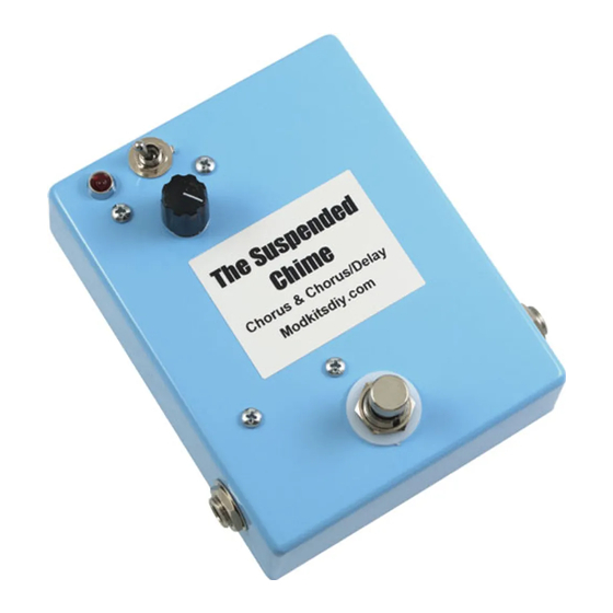
How to build an effects pedal for two digital effect options (chorus & chorus/delay).
The Suspended Chime uses the Accutronics BTSE-16FX Digital Sound Effector module to provide two
effects in one pedal, chorus and chorus with delay. The blend control allows you to go from subtle to lush
chorus effect. Flip the toggle switch for chorus with a 190 millisecond delay adding spatial depth to your tone.
Warning: This circuit was designed for use with a 9 VDC power supply only.
THE SUSPENDED CHIME (K-977)
LED
Chorus
Chorus
/Delay
The Suspended
Chorus & Chorus/Delay
Modkitsdiy.com
Chime
1
Copyright © 2016 by modkitsdiy.com
9 VDC
CENTER (-)
ADAPTER
Unplug when not in use
to save battery life.
FROM
GUITAR
OUT
Advertisement
Table of Contents

Related Manuals for Mod THE SUSPENDED CHIME


Summary of Contents for Mod THE SUSPENDED CHIME
- Page 1 How to build an effects pedal for two digital effect options (chorus & chorus/delay). The Suspended Chime uses the Accutronics BTSE-16FX Digital Sound Effector module to provide two effects in one pedal, chorus and chorus with delay. The blend control allows you to go from subtle to lush chorus effect.
-
Page 2: Table Of Contents
TABLE OF CONTENTS TOOL LIST ……………………………………………………………………………………….2 PARTS LIST DRAWINGS……………………………………………………………………..3 - 5 FINAL ASSEMBLY REFERENCE DRAWING…………………………………………………..6 SOLDERING TIPS ……………………………………………………………………………….7 …………………………………………..8 - 12 STEP BY STEP ASSEMBLY INSTRUCTIONS Section 1 – Mount Large Components ………………………………………………….8 Section 2 – Wire Large Components ……………………………………………………….9 Section 3 –... -
Page 3: Parts List Drawings
PARTS LIST 1 Stranded Wire (22 AWG) - White 3PDT Foot Switch K-PUL1569-WHITE (6 FT) P-H501 Enclosure P-H1590BBCE-LB Potentiometer, 25KL R-VAM25KL-SS B25K Terminal Strip with 8 Terminals P-0802H Knob (Scalloped Edge) P-K801 Terminal Strips with 5 Terminals Battery Clip P-0501H01 Lug Common S-H155 P-0501H05... - Page 4 PARTS LIST 2 DPDT Mini Toggle Switch 0.1µF Capacitor 100V P-H541 C-PEID1-100 104J 0.002µF Capacitor 100V Light Emitting Diode C-PEID002-100 P-L400 202J 4700µF Polarized Capacitor 16V C-ET4700-16 NPN BJT (2N5088) 4700µF 16V P-Q2N5088 5088 Digital Sound Effector (BTSE-16FX) P-RKBTSE-16FX E B C Voltage Regulator (78L05) P-QMC78L05 78L05...
- Page 5 PARTS LIST 3 220Ω Resistor ½ W 100kΩ Resistor ½ W R-A220 R-A100K 100K brown black brown yellow gold gold 2.2kΩ Resistor ½ W 1MΩ Resistor ½ W R-A2D2K R-A1M 2.2K brown black green gold gold 2MΩ Resistor ½ W 5.6kΩ...
-
Page 6: Final Assembly Reference Drawing
FINAL ASSEMBLY REFERENCE DRAWING This is a large version of the final assembly drawing. Refer to this drawing as you make your way through each step of the instructions. Before you make a new connection at a particular terminal or solder lug, notice how many other connections will be made at that terminal. That way you can decide whether it’s best for you to solder the connection and leave space open for future connections or hold off on soldering until after every connection at that location has been made. -
Page 7: Soldering Tips
SOLDERING TIPS It is important to make a good solder joint at each connection point. A cold solder joint is a connection that may look connected but is actually disconnected or intermittently connected. (A cold solder joint can keep your project from working.) Follow these tips to make a good solder joint. -
Page 8: Step By Step Assembly Instructions
SECTION 1 – Mount Large Components Please refer to DRAWING 1 and DRAWING 2. The anode (+) side of the LED is Orient the enclosure with the two 1/4" holes on top. indicated by a slightly longer lead and/or a positive sign. ... -
Page 9: Section 2 - Wire Large Components
SECTION 2 – Wire Large Components Please refer to DRAWING 3. Stripping wire, tinning wire and soldering. Throughout these instructions you will be told to strip and tin a length of wire numerous times. Unless noted otherwise, cut the wire to the length stated in the instructions. Then strip ¼” of insulation off each end. -
Page 10: Section 3 - Prepare The Btse-16Fx Module
SECTION 3 – Prepare the BTSE-16FX Module Six of the 16 pins will not be used: 2, 5, 7, 8, 13 and 15. To help identify these unused pins and help prevent shorting these pins with other connections we will insulate them. ... -
Page 11: Section 5 - Install The Btse-16Fx Module
Connect the 220 ohm resistor from terminal #19 to #20. Connect a 0.1µF cap from the pot’s “H” (hot) lug to terminal #18. Connect the 5.6K resistor from terminal #9 to #18. Connect a 10K resistor from terminal #21 to #23. ... -
Page 12: Section 6 - Finishing Up
Connect the BTSE-16FX module pins as listed: Tip: Route the wires along the module surface leaving room for the battery to fit on top of the module. CN1 pins Connect pin 1 to terminal #9. Connect pin 3 to terminal #1. ... -
Page 13: Assembly Drawings (4 Drawings)
DRAWING 1 1/4" 1/4" 1/8" 1/8" 9/32" INSIDE VIEW OF THE ENCLOSURE 1/8" 1/8" 3/8" 3/8" 15/32" BOTTOM DRAWING 2 Center-pin lug B25K RING SLEEVE SLEEVE Output Input... - Page 14 DRAWING 3 B25K RING SLEEVE SLEEVE Input Output black 5V_IN DGND 5.6K AGND IN-L AGND L-OUT RING SLEEVE Input Output...
Need help?
Do you have a question about the THE SUSPENDED CHIME and is the answer not in the manual?
Questions and answers