Table of Contents
Advertisement
Quick Links
THE RING RESONATOR (K-975)
OUTPUT
BOOST
9 VDC
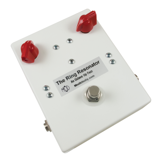
The Ring Resonator
CENTER (-)
An Octave Up Fuzz
ADAPTER
Modkitsdiy.com
TO
FROM
AMP
GUITAR
IN
OUT
Unplug when not in use
to save battery life.
Use these instructions to learn:
How to build an effects pedal for octave fuzz.
The Ring Resonator is an octave up fuzz effect that is an all analog design that captures those late 60's
octave up fuzz tones. Transformer coupled germanium diodes produce sounds that range from a subtle
octave up to thick, harmonically rich sonic textures, and synth like tones. Experimenting with different
pickups and tone control settings on your guitar with the Ring Resonator can also produce sitar like sounds.
Warning: This circuit was designed for use with a 9 VDC power supply only.
1
Copyright © 2016 by modkitsdiy.com
Advertisement
Table of Contents

Related Manuals for Mod The Ring Resonator


Summary of Contents for Mod The Ring Resonator
- Page 1 How to build an effects pedal for octave fuzz. The Ring Resonator is an octave up fuzz effect that is an all analog design that captures those late 60's octave up fuzz tones. Transformer coupled germanium diodes produce sounds that range from a subtle octave up to thick, harmonically rich sonic textures, and synth like tones.
-
Page 2: Table Of Contents
TABLE OF CONTENTS TOOL LIST ……………………………………………………………………………………….2 PARTS LIST DRAWINGS……………………………………………………………………...3, 4 FINAL ASSEMBLY REFERENCE DRAWING…………………………………………………..5 SOLDERING TIPS ……………………………………………………………………………….6 STEP BY STEP ASSEMBLY INSTRUCTIONS …………………………………………..7 - 10 Section 1 – Mount Large Components ………………………………………………….7 Section 2 – Wire Large Components ……………………………………………………….7 Section 3 – Mount Components to Terminal Strips ………..……………………………..8 Section 4 –... -
Page 3: Parts List Drawings
PARTS LIST 1 Stranded Wire (22 AWG) - Red DPDT Foot Switch K-PUL1569 (3 FT) P-H498 Enclosure P-H1590BBCE-W Potentiometers: 1KL and 500KA R-VA1KL R-VA500KA Mini Chicken Head Knob P-K900R Terminal Strip with 5 Terminals Battery Clip P-0501H S-H155 Terminal Strip with 8 Terminals ¼”... - Page 4 PARTS LIST 2 Audio Transformer (1.5K : 600 Ω) 220kΩ Resistor ½ W 220Ω Resistor ½ W P-T42TM022 R-A220K R-A220 220K yellow brown gold gold NPN BJT (2N5088) P-Q2N5088 470Ω Resistor ½ W 680kΩ Resistor ½ W R-A470 R-A680K 5088 680K yellow blue...
-
Page 5: Final Assembly Reference Drawing
FINAL ASSEMBLY REFERENCE DRAWING This is a large version of the final assembly drawing. Refer to this drawing as you make your way through each step of the instructions. Before you make a new connection at a particular terminal or solder lug, notice how many other connections will be made at that terminal. That way you can decide whether it’s best for you to solder the connection and leave space open for future connections or hold off on soldering until after every connection at that location has been made. -
Page 6: Soldering Tips
SOLDERING TIPS It is important to make a good solder joint at each connection point. A cold solder joint is a connection that may look connected but is actually disconnected or intermittently connected. (A cold solder joint can keep your project from working.) Follow these tips to make a good solder joint. -
Page 7: Step By Step Assembly Instructions
SECTION 1 – Mount Large Components Please refer to DRAWING 1 and DRAWING 2. Orient the enclosure with the two 5/16" holes on top. Using the seven screws, nuts and lock washers provided, fasten the five terminal strips to match DRAWING 2. -
Page 8: Section 3 - Mount Components To Terminal Strips
Strip and tin a 2" piece of wire and connect Footswitch lug 5 to the output jack’s tip lug. Strip and tin a 1 ½” piece of wire and connect Footswitch lugs 1 and 4. Strip and tin a 2” piece of wire and connect Footswitch lug 2 to the input jack’s tip lug. Strip and tin a 4"... - Page 9 Connect the 820K resistor to terminals #2 and #3. Push this component down slightly to allow room for the next component. Do not solder the connection on terminal #3, yet. Connect one of the 33µF caps to terminals #1 and #3. Make sure the negative end negative (-) end of the cap is connected to terminal #1.
-
Page 10: Section 4 - Finishing Up
Connect the remaining 100µF cap to terminals #17 and #19. negative end 100µF 25V Make sure the negative (-) end is connected to #19. mounting tabs Press the metal mounting tabs of the transformer inward so they are flush with the bottom of the transformer. Now place the transformer upside down in the enclosure in the area shown on DRAWING 4. -
Page 11: Assembly Drawings (4 Drawings)
DRAWING 1 5/16" 5/16" 1/8" 1/8" 1/8" INSIDE VIEW OF THE ENCLOSURE 15/32" 1/8" 1/8" 1/8" 1/8" 15/32" 3/8" 3/8" DRAWING 2 500KA... - Page 12 DRAWING 3 500KA DRAWING 4 “P” 500KA .001µ 1.2K 150p 3906 200K 220K 680K .1µ black...
Need help?
Do you have a question about the The Ring Resonator and is the answer not in the manual?
Questions and answers