Table of Contents
Advertisement
Quick Links
THE CONTORTIONIST (K-990)
OUTPUT
GAIN
9 VDC
The Contortionist
CENTER (-)
High Octane Fuzz Box
ADAPTER
Modkitsdiy.com
TO
FROM
AMP
GUITAR
IN
OUT
Unplug when not in use
to save battery life.
Use these instructions to learn:
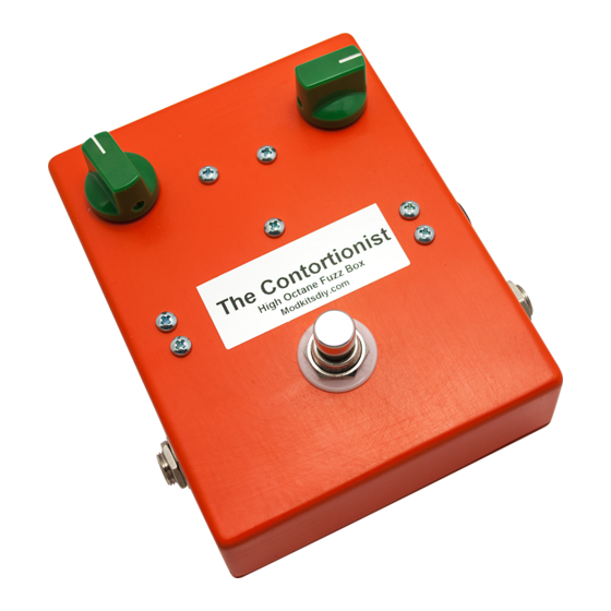
How to build an effects pedal for fuzz with non-selective frequency tripler.
The Contortionist kit is a limited edition, all analog, high octane fuzz box. It produces fuzz with layered
octave overtones similar to those produced by an electronic-bow. The frequency multiplier circuitry creates
harmonics that swell and recede depending on gain setting, pick attack, neck position and pickup. This is a
high gain circuit that can put out up to 2 volts and will provide ample amounts of sustain.
Warning: This circuit was designed for use with a 9 VDC power supply only.
www.modkitsdiy.com
1
Copyright © 2014 by modkitsdiy.com
Advertisement
Table of Contents

Summary of Contents for Mod CONTORTIONIST
- Page 1 How to build an effects pedal for fuzz with non-selective frequency tripler. The Contortionist kit is a limited edition, all analog, high octane fuzz box. It produces fuzz with layered octave overtones similar to those produced by an electronic-bow. The frequency multiplier circuitry creates harmonics that swell and recede depending on gain setting, pick attack, neck position and pickup.
-
Page 2: Table Of Contents
TABLE OF CONTENTS TOOL LIST p. 2 PARTS LIST DRAWINGS pp. 3, 4 SOLDERING TIPS p. 5 STEP BY STEP ASSEMBLY INSTRUCTIONS pp. 6 - 9 Section 1 - Mount Large Components p. 6 Section 2 - Wire Large Components p. -
Page 3: Parts List Drawings
PARTS LIST 1 Stranded Wire (22 AWG) - Red DPDT Foot Switch K-PUL1569 (3.5 FT) P-H498 Enclosure P-H1590BBCE-O Potentiometers: 1KL and 250KA R-VA1KL R-VA250KA Dark Green Knob with White Line Terminal Strip with 2 Terminals - 1st Com P-K380GRN P-0201H01 Battery Clip Terminal Strip with 2 Terminals - 2nd Com S-H155... - Page 4 PARTS LIST 2 NPN Darlington (MPSA13) 10k Resistor ½ W P-QMPSA13 R-A10K brown black orange E B C gold NPN BJT (2N3904TAR) 820k Resistor ½ W K-P2N3904TAR R-A820K 820K 3904 gray E B C yellow gold PNP BJT (2N3906) 3M ½ W K-PQ-2N3906 R-A3M 3906...
-
Page 5: Soldering Tips
SOLDERING TIPS It is important to make a good solder joint at each connection point. A cold solder joint is a connection that may look connected but is actually disconnected or intermittently connected. (A cold solder joint can keep your project from working.) Follow these tips to make a good solder joint. -
Page 6: Step By Step Assembly Instructions
SECTION 1 Mount Large Components Please refer to DRAWING 1 and DRAWING 2. Orient the enclosure with the two 5/16" holes on top. Using the seven screws, nuts and lock washers provided, fasten the five terminal strips to match DRAWING 2. Fasten the two 2 lug terminal strips and the 3 lug terminal strips first. - Page 7 Please note that each terminal has been numbered as illustrated here and will be referred to as a terminal #_ when connecting different components and wires throughout the assembly instructions. Strip and tin a 2" piece of wire and connect footswitch lug 5 to the output jack's tip lug.
-
Page 8: Section 3 - Mount Components To Terminal Strips
SECTION 3 Mount Components to Terminal Strips Please refer to DRAWING 4. Connect and solder all the following components to their respective terminals as listed. (Make sure that none of the component leads are so close together that it could cause an unintended short). Unless noted otherwise, connect means to trim the component s leads to a reasonable length, wrap them tightly around their connection points and solder. -
Page 9: Section 4 - Finishing Up
SECTION 4 Finishing Up It s always a good idea to thoroughly double-check your connections before applying power. This will minimize the risk of damaging components. Fasten the knobs to the potentiometer shafts by tightening their set screws. Install a 9 volt battery if needed. -
Page 10: Assembly Drawings (4 Drawings)
DRAWING 1 5/16" 5/16" 1/8" 1/8" 1/8" INSIDE VIEW OF THE 15/32" 1/8" 1/8" ENCLOSURE 1/8" 1/8" 15/32" 3/8" 3/8" DRAWING 2 FUZZ VOLUME 250KA... - Page 11 DRAWING 3 250KA RING SLEEVE SLEEVE DRAWING 4 820K 250KA 3906 RING SLEEVE SLEEVE...


Need help?
Do you have a question about the CONTORTIONIST and is the answer not in the manual?
Questions and answers