
Related Manuals for ClimateMaster CS Series


Summary of Contents for ClimateMaster CS Series
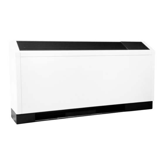
- Page 1 CS/CL Series Console Air Conditioners Water Source Heat Pumps Installation, Operation, & Maintenance Instructions...
-
Page 2: Table Of Contents
TABLE OF CONTENTS Page General Information Inspection Introduction Storage Unit Protection Pre-Installation Installation Supply and Return Hoses Installation of Supply and Return Piping Condensate Piping Electrical Wiring Optional Night Setback Control Optional CMC-2000 Controller Optional Wall Mounted Thermostat Start-Up Preperation System Checkout Unit Start-Up Maintenance... -
Page 3: General Information
Before unit start-up, read all all necessary claims with the carrier. Notify the manuals and become familiar with the unit and its ClimateMaster Traffic Department within fifteen (15) operation. Thoroughly check out the system before days of receipt of all damaged shipments. -
Page 4: Installation
Optional pressure-rated hose assemblies are available for at initial start-up. These checklists are not a substitute use with ClimateMaster CS/CL Units. Use the following for the detailed information found in the Installation guidelines when installing supply and return hose section of this manual. -
Page 5: Installation Of Supply And Return Piping
Supply and Return Piping All field installed wiring, including the electrical ground, MUST comply with the National Electrical Code as well System piping MUST comply with all applicable codes. as applicable local codes. In addition, all field wiring 1. Install a drain valve at the base of each supply and must conform to the Class II temperature limitations return riser to enable system flushing at start-up and described in the NEC. -
Page 6: Optional Cmc-2000 Controller
Thermostat is used then the wiring between the When desired, the unit can be furnished with a 24-volt thermostat and the unit must be a 4 shielded control circuit which is field-wired to a ClimateMaster- conductor. See ET Thermostat IOM (p/n 69197318). supplied accessory remote thermostat. -
Page 7: Start-Up Preperation
START-UP PREPARATION System Cleaning and Flushing 6. Set the boiler to raise the loop temperature to approximately 85° F. Open the drain at the lowest Cleaning and flushing the unit is the single most impor- point in the system. Verify that make-up water tant step to ensure proper start-up and continued efficient replacement rate equals rate of bleed. -
Page 8: System Checkout
SYSTEM CHECKOUT When the installation is complete and the system is cleaned and flushed, follow the System Checkout procedure outline below. 1. Voltage: Ensure voltage is within the utilization 9. Freeze Protection for Water System: Verify range specifications of the unit compressor and fan freeze protection is provided for the outdoor portion motor. -
Page 9: Unit Start-Up
UNIT START-UP Use the procedure outlined below to initiate proper unit start-up: Operating Limits NOTE: This equipment is designed for indoor installation ONLY. Environment: This equipment is designed for indoor installation ONLY. When the disconnect switch is closed, high voltage is Power Supply: A voltage variation of +/- 10% of present in some areas of the electrical panel. - Page 10 Unit Start-Up / Heating b. Look for wiring errors. Check for loose terminal screws where wire connections have been made on both the line and low-voltage terminal boards. a. Adjust the unit thermostat to the warmest setting c. Check for dirty filters. A clogged filter will cause and turn the fan speed switch to "HI".
-
Page 11: Maintenance
Perform the maintenance procedures outlined below at Safety Control Reset the intervals indicated. All ClimateMaster heat pumps are furnished with high- pressure, low-pressure and low-temperature cutouts to prevent the machine from operating at abnormal condi- To prevent injury or death due to electrical shock or tions of temperature or water flow. - Page 12 Page 12...
-
Page 13: Warranty
Page 13... - Page 14 Page 14...
- Page 15 Page 15...
- Page 16 ClimateMaster works continually to improve its products. As a result, the design and specifications of each product at the time of order may be changed without notice and may not be as described herein. Please contact ClimateMaster’s Customer Service Department at 1-405-745-6000 for specific information on the current design and specifications.
Need help?
Do you have a question about the CS Series and is the answer not in the manual?
Questions and answers