Table of Contents
Advertisement
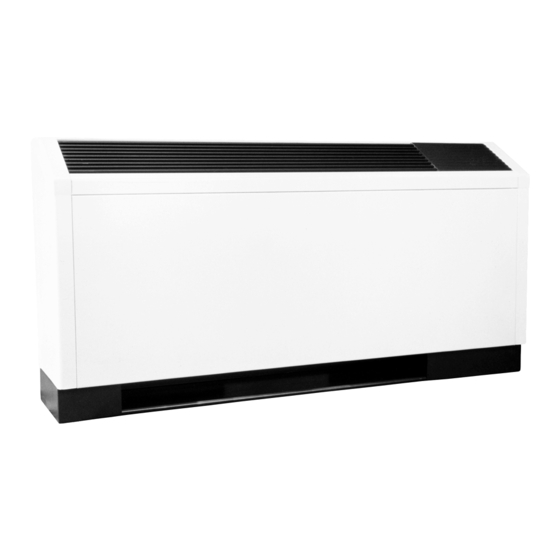
Console (CCE) Series
Tranquility Console
(TRC) Series
Commercial Console
Water-Source Heat Pumps
50Hz & 60Hz
Installation, Operation &
Maintenance Instructions
97B0035N01
Revision: 5 Nov., 2009B
Table of Contents
Piping Installation
Electrical Wiring - Line Voltage
Electrical Wiring - Low Voltage
Electrical Wiring Schematics
CXM/DXM Safety Control Reset
Refrigerant Circuit Diagram
Warranties
3-4
5
6
6
7-9
10
11
12-14
15
16
17
18
20
21-23
24
25
26
27-31
32-34
35-36
37
38
39
40
41
43
44-45
46
47-48
50
Advertisement
Table of Contents
Troubleshooting

Related Manuals for ClimateMaster CCE07 Series


Summary of Contents for ClimateMaster CCE07 Series
-
Page 1: Table Of Contents
Console (CCE) Series Tranquility Console (TRC) Series Table of Contents Model Nomenclature General Information Storage Pre-Installation Physical Data Installation Condensate Piping Piping Connection 12-14 Piping Installation Water-Loop Heat Pump Applications Ground-Loop Heat Pump Applications Ground-Water Heat Pump Applications Water Quality Standards Electrical Wiring - Line Voltage 21-23 Electrical Wiring - Low Voltage... -
Page 3: Model Nomenclature
T H E S M A R T S O L U T I O N F O R E N E R G Y E F F I C I E N C Y C o n s o l e s R e v. - Page 4 C L I M AT E M A S T E R W AT E R - S O U R C E H E AT P U M P S C o n s o l e s R e v. : 5 N o v. , 2 0 0 9 B Model Nomenclature: Tranquility Console (TRC) Series (60Hz) 1 2 3 T R C...
-
Page 5: General Information
T H E S M A R T S O L U T I O N F O R E N E R G Y E F F I C I E N C Y C o n s o l e s R e v. -
Page 6: Storage
C L I M AT E M A S T E R W AT E R - S O U R C E H E AT P U M P S C o n s o l e s R e v. : 5 N o v. , 2 0 0 9 B General Information 3. -
Page 7: Physical Data
T H E S M A R T S O L U T I O N F O R E N E R G Y E F F I C I E N C Y C o n s o l e s R e v. -
Page 8: Unit Physical Data
C L I M AT E M A S T E R W AT E R - S O U R C E H E AT P U M P S C o n s o l e s R e v. : 5 N o v. , 2 0 0 9 B Unit Physical Data Tranquility Console (TRC) Series (60Hz) Model... -
Page 9: Physical Data
T H E S M A R T S O L U T I O N F O R E N E R G Y E F F I C I E N C Y C o n s o l e s R e v. -
Page 10: Installation
Protect the cabinet from damage Optional pressure-rated hose assemblies are available during installation by returning it to its original for use with ClimateMaster Console Units. Use the packaging until required. following guidelines when installing supply and return 3. Remove compressor isolation plate shipping screws hose assemblies. -
Page 11: Condensate Piping
T H E S M A R T S O L U T I O N F O R E N E R G Y E F F I C I E N C Y C o n s o l e s R e v. - Page 12 C L I M AT E M A S T E R W AT E R - S O U R C E H E AT P U M P S C o n s o l e s R e v. : 5 N o v. , 2 0 0 9 B Piping Connections - CCE Figure 1b: Water Connection Details 5.36...
-
Page 13: Piping Connection
T H E S M A R T S O L U T I O N F O R E N E R G Y E F F I C I E N C Y C o n s o l e s R e v. - Page 14 C L I M AT E M A S T E R W AT E R - S O U R C E H E AT P U M P S C o n s o l e s R e v. : 5 N o v. , 2 0 0 9 B Piping Connections - TRC Size 18 1.62 (41)
- Page 15 fi nger-tight plus one quarter turn. Tighten steel fi ttings psig and a cut-in pressure of 250 psig. This pressure switch as necessary. can be ordered from ClimateMaster with a 1/4” internal fl are connection as part number 39B0005N02. Optional pressure-rated hose assemblies designed specifi...
-
Page 16: Water-Loop Heat Pump Applications
3.5 gpm per ton [2.9 and 4.5 l/m per kW] of cooling a major portion of the mechanical room plumbing. In capacity. ClimateMaster recommends 3 gpm per ton piping systems expected to utilize water temperatures [3.9 l/m per kW] for most applications of water loop heat below 50°F [10°C], 1/2”... -
Page 17: Ground-Loop Heat Pump Applications
T H E S M A R T S O L U T I O N F O R E N E R G Y E F F I C I E N C Y C o n s o l e s R e v. -
Page 18: Ground-Water Heat Pump Applications
C L I M AT E M A S T E R W AT E R - S O U R C E H E AT P U M P S C o n s o l e s R e v. : 5 N o v. , 2 0 0 9 B Ground-Water Heat Pump Applications Open Loop - Ground Water Systems Expansion Tank and Pump... - Page 19 235 psig and a cut-in pressure of 190 psig. This pressure switch can be ordered from ClimateMaster with a 1/4” internal fl are connection as part number 39B0005N01. c l i m a t e m a s t e r. c o m...
-
Page 20: Water Quality Standards
C L I M AT E M A S T E R W AT E R - S O U R C E H E AT P U M P S C o n s o l e s R e v. : 5 N o v. , 2 0 0 9 B Water Quality Standards Table 2: Water Quality Standards 100 F (38 C) - Page 21 T H E S M A R T S O L U T I O N F O R E N E R G Y E F F I C I E N C Y C o n s o l e s R e v.
- Page 22 C L I M AT E M A S T E R W AT E R - S O U R C E H E AT P U M P S C o n s o l e s R e v. : 5 N o v. , 2 0 0 9 B Electrical - Line Voltage Table 5a: TRC Electrical Data (60Hz) Total...
- Page 23 T H E S M A R T S O L U T I O N F O R E N E R G Y E F F I C I E N C Y C o n s o l e s R e v.
- Page 24 C L I M AT E M A S T E R W AT E R - S O U R C E H E AT P U M P S C o n s o l e s R e v. : 5 N o v. , 2 0 0 9 B Electrical - Low Voltage Unit-Mounted Controls, TRC &...
-
Page 25: Thermostat Wiring
fi eld-installed low-voltage wiring is required. Thermostat Compressor When desired, the unit can be furnished with a 24-volt control circuit which is fi eld-wired to a ClimateMaster- supplied accessory remote thermostat. Reversing Valve Zone integrity must be maintained to effi ciently control 24Vac Hot units or groups of units. -
Page 26: Electrical Wiring Diagram Matrix
C o n s o l e s R e v. : 5 N o v. , 2 0 0 9 B TRC/CCE Series Wiring Diagram Matrix DIAGRAMS CAN BE LO CAT ED ONLINE AT CLIMATEMASTER.COM USING THE PART NUM BERS PRESENTED BELOW. Wiring Diagram Model... - Page 27 T H E S M A R T S O L U T I O N F O R E N E R G Y E F F I C I E N C Y C o n s o l e s R e v.
- Page 28 C L I M AT E M A S T E R W AT E R - S O U R C E H E AT P U M P S C o n s o l e s R e v. : 5 N o v. , 2 0 0 9 B Typical Wiring Diagram - Remote Mounted Thermosat CCE &...
- Page 29 T H E S M A R T S O L U T I O N F O R E N E R G Y E F F I C I E N C Y C o n s o l e s R e v.
- Page 30 C L I M AT E M A S T E R W AT E R - S O U R C E H E AT P U M P S C o n s o l e s R e v. : 5 N o v. , 2 0 0 9 B Typical Wiring Diagram - Unit Mounted Manual &...
- Page 31 T H E S M A R T S O L U T I O N F O R E N E R G Y E F F I C I E N C Y C o n s o l e s R e v.
-
Page 32: Cxm Controls
C L I M AT E M A S T E R W AT E R - S O U R C E H E AT P U M P S C o n s o l e s R e v. : 5 N o v. , 2 0 0 9 B CXM Controls On = Enabled. -
Page 33: Dxm Controls
Test LED Description of Fault LED (red) Alarm Relay Operation (green) (yellow) as recommended by ClimateMaster technical services. Normal mode Open Cycle (closed 5 sec, Not Clipped = 30°F [-1°C]. Clipped = 10°F Normal mode with UPS Flashing Code 8 open 25 sec) [-12°C]. - Page 34 C L I M AT E M A S T E R W AT E R - S O U R C E H E AT P U M P S C o n s o l e s R e v. : 5 N o v. , 2 0 0 9 B DXM Controls cool mode, Y1 is the input call for cooling stage 1;...
- Page 35 T H E S M A R T S O L U T I O N F O R E N E R G Y E F F I C I E N C Y C o n s o l e s R e v.
-
Page 36: Cxm/Dxm Controls
C L I M AT E M A S T E R W AT E R - S O U R C E H E AT P U M P S C o n s o l e s R e v. : 5 N o v. , 2 0 0 9 B Safety Features - CXM/DXM Controls If a UPS condition occurs, the control will immediately CXM/DXM Control Start-up Operation... -
Page 37: Unit Commissioning And Operating Conditions
T H E S M A R T S O L U T I O N F O R E N E R G Y E F F I C I E N C Y C o n s o l e s R e v. -
Page 38: Piping System Cleaning And Flushing
ClimateMaster will not be responsible or liable for and repair as appropriate. damages from water leaks due to inadequate or 4. Verify that all strainers are in place (ClimateMaster lack of a pressurized leak test, or damages caused recommends a strainer with a #20 stainless steel wire by exceeding the maximum pressure rating during mesh). -
Page 39: Unit And System Checkout Procedure
T H E S M A R T S O L U T I O N F O R E N E R G Y E F F I C I E N C Y C o n s o l e s R e v. -
Page 40: Unit Start-Up
5. Two factors determine the operating limits still does not operate, contact a trained service of ClimateMaster heat pumps, (a) return air technician to insure proper diagnosis and repair of temperature, and (b) water temperature. When any the equipment. -
Page 41: Unit Operating Conditions
T H E S M A R T S O L U T I O N F O R E N E R G Y E F F I C I E N C Y C o n s o l e s R e v. - Page 42 C L I M AT E M A S T E R W AT E R - S O U R C E H E AT P U M P S C o n s o l e s R e v. : 5 N o v. , 2 0 0 9 B Unit Operating Conditions Unit Operating Conditions Table: 10 TRC Series Typical Operating Pressures and Temperatures (60 Hz I.P.
-
Page 43: Preventive Maintenance
T H E S M A R T S O L U T I O N F O R E N E R G Y E F F I C I E N C Y C o n s o l e s R e v. -
Page 44: Functional & Performance Troubleshooting
C L I M AT E M A S T E R W AT E R - S O U R C E H E AT P U M P S C o n s o l e s R e v. : 5 N o v. , 2 0 0 9 B Functional Troubleshooting Fault Htg Clg Possible Cause... -
Page 45: Performance Troubleshooting
T H E S M A R T S O L U T I O N F O R E N E R G Y E F F I C I E N C Y C o n s o l e s R e v. - Page 46 C L I M AT E M A S T E R W AT E R - S O U R C E H E AT P U M P S C o n s o l e s R e v. : 5 N o v. , 2 0 0 9 B Troubleshooting Form Model Number: ________________________ Serial Number: ________________________...
- Page 47 T H E S M A R T S O L U T I O N F O R E N E R G Y E F F I C I E N C Y C o n s o l e s R e v.
- Page 48 C L I M AT E M A S T E R W AT E R - S O U R C E H E AT P U M P S C o n s o l e s R e v. : 5 N o v. , 2 0 0 9 B Warranty (International) C l i m a t e M a s t e r W a t e r- S o u r c e H e a t i n g a n d C o o l i n g S y s t e m s...
- Page 49 T H E S M A R T S O L U T I O N F O R E N E R G Y E F F I C I E N C Y C o n s o l e s R e v.
-
Page 50: Revision History
97B0035N01 ClimateMaster works continually to improve its products. As a result, the design and specifi cations of each product at the time for order may be changed without notice and may not be as described herein. Please contact ClimateMaster’s Customer Service Department at 1-405-745-6000 for specifi...
Need help?
Do you have a question about the CCE07 Series and is the answer not in the manual?
Questions and answers