ClimateMaster Tranquility 27 Installation, Operation & Maintenance Instructions Manual

ClimateMaster Tranquility 27 Installation, Operation & Maintenance Instructions Manual

Tt/ts series

Advertisement

Advertisement

Table of Contents
loading

Summary of Contents for ClimateMaster Tranquility 27

  • Page 1: Table Of Contents

    H&V Products Tranquility 27 (TT) Series ® Tranquility 20™ (TS) Series Residential Horizontal & Vertical 
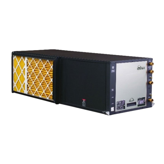
Packaged Geothermal Heat Pumps Installation, Operation & Maintenance Instructions 97B0045N03 Revision: 9 March, 2011B Table of Contents Model Nomenclature Safety Features – CXM Control 30-32...
  • Page 2 This page was intentionally left blank.
  • Page 3: Model Nomenclature

    R e s i d e n t i a l H & V - 6 0 H z H F C - 4 1 0 A R e v. : 9 M a r c h , 2 0 1 1 B Model Nomenclature: General Overview NOTE: Above model nomenclature is a general reference.
  • Page 4: Storage

    R e s i d e n t i a l H & V - 6 0 H z H F C - 4 1 0 A R e v. : 9 M a r c h , 2 0 1 1 B General Information Pre Installation Inspection...
  • Page 5: Horizontal Installation

    R e s i d e n t i a l H & V - 6 0 H z H F C - 4 1 0 A R e v. : 9 M a r c h , 2 0 1 1 B Horizontal Installation Mounting Horizontal Units Horizontal Unit Location...
  • Page 6 R e s i d e n t i a l H & V - 6 0 H z H F C - 4 1 0 A R e v. : 9 M a r c h , 2 0 1 1 B Horizontal Installation Figure 3: Typical Horizontal Unit Installation Air Coil - To obtain maximum performance, the air coil should...
  • Page 7: Field Conversion Of Air Discharge

    R e s i d e n t i a l H & V - 6 0 H z H F C - 4 1 0 A R e v. : 9 M a r c h , 2 0 1 1 B Field Conversion of Air Discharge Overview - Horizontal units can be fi...
  • Page 8: Duct System Installation

    R e s i d e n t i a l H & V - 6 0 H z H F C - 4 1 0 A R e v. : 9 M a r c h , 2 0 1 1 B Horizontal Installation Condensate Piping Figure 6: Horizontal Condensate Connection...
  • Page 9: Vertical Installation

    R e s i d e n t i a l H & V - 6 0 H z H F C - 4 1 0 A R e v. : 9 M a r c h , 2 0 1 1 B Vertical Installation Figure 7: Vertical Unit Mounting Vertical Unit Location...
  • Page 10 R e s i d e n t i a l H & V - 6 0 H z H F C - 4 1 0 A R e v. : 9 M a r c h , 2 0 1 1 B Vertical Installation Sound Attenuation for Vertical Units - Sound attenuation Condensate Piping for Vertical Units - Vertical units utilize...
  • Page 11: Water Connection Installation

    R e s i d e n t i a l H & V - 6 0 H z H F C - 4 1 0 A R e v. : 9 M a r c h , 2 0 1 1 B Water Connection Installation The female locking ring is threaded onto the pipe threads External Flow Controller Mounting...
  • Page 12 R e s i d e n t i a l H & V - 6 0 H z H F C - 4 1 0 A R e v. : 9 M a r c h , 2 0 1 1 B Ground-Loop Heat Pump Applications antifreeze solution is used in most areas to prevent freezing.
  • Page 13: Open Loop - Ground Water Systems

    R e s i d e n t i a l H & V - 6 0 H z H F C - 4 1 0 A R e v. : 9 M a r c h , 2 0 1 1 B Ground-Loop Heat Pump Applications Open Loop - Ground Water Systems Table 2: Antifreeze Percentages by Volume...
  • Page 14 R e s i d e n t i a l H & V - 6 0 H z H F C - 4 1 0 A R e v. : 9 M a r c h , 2 0 1 1 B Ground-Water Heat Pump Applications valve or water control valve on the discharge line.
  • Page 15: Water Quality Standards

    Rev.: 3/22/2012 The ClimateMaster Water Quality Table provides water quality requirements for ClimateMaster coaxial heat exchangers. When water properties are outside of those requirements, an external secondary heat exchanger must be used to isolate the heat pump heat exchanger from the unsuitable water. Failure to do so will void the warranty for the coaxial heat exchanger.
  • Page 16: Hot Water Generator

    R e s i d e n t i a l H & V - 6 0 H z H F C - 4 1 0 A R e v. : 7 A u g . , 2 0 1 1 B Hot Water Generator The HWG (Hot Water Generator) or desuperheater option Electric water heaters are recommended.
  • Page 17 R e s i d e n t i a l H & V - 6 0 H z H F C - 4 1 0 A R e v. : 9 M a r c h , 2 0 1 1 B Hot Water Generator ANTI-SCALD Installation...
  • Page 18: Hot Water Generator

    R e s i d e n t i a l H & V - 6 0 H z H F C - 4 1 0 A R e v. : 9 M a r c h , 2 0 1 1 B Hot Water Generator Warning! The HWG pump Is fully wired from the 5.
  • Page 19: Electrical - Line Voltage

    R e s i d e n t i a l H & V - 6 0 H z H F C - 4 1 0 A R e v. : 9 M a r c h , 2 0 1 1 B Electrical - Line Voltage WARNING! CAUTION!
  • Page 20 R e s i d e n t i a l H & V - 6 0 H z H F C - 4 1 0 A R e v. : 9 M a r c h , 2 0 1 1 B Electrical - Line Voltage Figure 16: TT/TS Single Phase Line Voltage WARNING!
  • Page 21: Electrical - Low Voltage Wiring

    R e s i d e n t i a l H & V - 6 0 H z H F C - 4 1 0 A R e v. : 9 M a r c h , 2 0 1 1 B Electrical - Low Voltage Wiring Thermostat Connections Low Water Temperature Cutout Selection...
  • Page 22: Accessory Connections

    Therefore, only relay or triac based thermostats should be used. Figure 23: Two-Stage Piping Two-stage Units Solenoid Tranquility 27™ (TT) two-stage units should be designed with Flow Valve Regulator two parallel valves for ground water applications to limit water use during rst stage operation.
  • Page 23: Electrical - Thermostat Wiring

    300 psig and a cut-in pressure of 250 psig. This pressure switch can 24Vac Hot be ordered from ClimateMaster with a 1/4” internal are 24Vac Common connection as part number 39B0005N02. Fault LED...
  • Page 24: Ecm Blower Control

    1. Heating Settings: The heating setting determines the heating ® CFM for Tranquility 27 (TT) and Tranquility 20 (TS) units. Tap 1 is the lowest CFM setting, while tap 4 is the highest CFM setting.
  • Page 25 R e s i d e n t i a l H & V - 6 0 H z H F C - 4 1 0 A R e v. : 9 M a r c h , 2 0 1 1 B ECM Blower Control Table 5: ECM Board Tap Settings Cooling settings: TT, TS Units...
  • Page 26: Blower Data

    R e s i d e n t i a l H & V - 6 0 H z H F C - 4 1 0 A R e v. : 9 M a r c h , 2 0 1 1 B Tranquility 27 (TT) Series ECM Blower Performance Data ®...
  • Page 27 R e s i d e n t i a l H & V - 6 0 H z H F C - 4 1 0 A R e v. : 9 M a r c h , 2 0 1 1 B Tranquility 20™...
  • Page 28 R e s i d e n t i a l H & V - 6 0 H z H F C - 4 1 0 A R e v. : 9 M a r c h , 2 0 1 1 B Tranquility 20™...
  • Page 29: Cxm Controls

    R e s i d e n t i a l H & V - 6 0 H z H F C - 4 1 0 A R e v. : 9 M a r c h , 2 0 1 1 B CXM Controls DDC operation.
  • Page 30: Safety Features - Cxm Control

    R e s i d e n t i a l H & V - 6 0 H z H F C - 4 1 0 A R e v. : 9 M a r c h , 2 0 1 1 B CXM Controls Air coil low temperature (FP2): The FP2 thermistor temperature Safety Features –...
  • Page 31 R e s i d e n t i a l H & V - 6 0 H z H F C - 4 1 0 A R e v. : 9 M a r c h , 2 0 1 1 B CXM Controls CXM Control Start-up Operation The control will not operate until all inputs and safety controls...
  • Page 32 R e s i d e n t i a l H & V - 6 0 H z H F C - 4 1 0 A R e v. : 9 M a r c h , 2 0 1 1 B CXM Controls Safety Features –...
  • Page 33: Unit Commissioning And Operating Conditions

    R e s i d e n t i a l H & V - 6 0 H z H F C - 4 1 0 A R e v. : 9 M a r c h , 2 0 1 1 B Unit Commissioning And Operating Conditions Operating Limits Environment –...
  • Page 34: Unit Start-Up And Operating Conditions

    R e s i d e n t i a l H & V - 6 0 H z H F C - 4 1 0 A R e v. : 9 M a r c h , 2 0 1 1 B Unit Start-Up and Operating Conditions operate in the proper sequence.
  • Page 35: Unit Start-Up Procedure

    R e s i d e n t i a l H & V - 6 0 H z H F C - 4 1 0 A R e v. : 9 M a r c h , 2 0 1 1 B Unit Start-Up Procedure e.
  • Page 36: Coax Pressure Drop Tables

    R e s i d e n t i a l H & V - 6 0 H z H F C - 4 1 0 A R e v. : 9 M a r c h , 2 0 1 1 B Unit Operating Conditions Table 9a: TT Coax Water Pressure Drop Table 9b: TS Coax Water Pressure Drop...
  • Page 37 R e s i d e n t i a l H & V - 6 0 H z H F C - 4 1 0 A R e v. : 9 M a r c h , 2 0 1 1 B Unit Operating Conditions Table 11: TT Series Typical Unit Operating Pressures and Temperatures TT026...
  • Page 38 R e s i d e n t i a l H & V - 6 0 H z H F C - 4 1 0 A R e v. : 9 M a r c h , 2 0 1 1 B Unit Operating Conditions Table 11: TT Series Typical Unit Operating Pressures and Temperatures: Continued TT064...
  • Page 39 R e s i d e n t i a l H & V - 6 0 H z H F C - 4 1 0 A R e v. : 9 M a r c h , 2 0 1 1 B Unit Operating Conditions Table 12: TS Series Typical Unit Operating Pressures and Temperatures: Continued Full Load Cooling - without HWG active...
  • Page 40 R e s i d e n t i a l H & V - 6 0 H z H F C - 4 1 0 A R e v. : 9 M a r c h , 2 0 1 1 B Unit Operating Conditions Table 12: TS Series Typical Unit Operating Pressures and Temperatures: Continued Full Load Cooling - without HWG active...
  • Page 41: Unit Operating Conditions

    R e s i d e n t i a l H & V - 6 0 H z H F C - 4 1 0 A R e v. : 9 M a r c h , 2 0 1 1 B Unit Operating Conditions Table 12: TS Series Typical Unit Operating Pressures and Temperatures: Continued Full Load Cooling - without HWG active...
  • Page 42: Preventive Maintenance

    R e s i d e n t i a l H & V - 6 0 H z H F C - 4 1 0 A R e v. : 9 M a r c h , 2 0 1 1 B Preventive Maintenance Water Coil Maintenance Condensate Drain...
  • Page 43: Troubleshooting

    R e s i d e n t i a l H & V - 6 0 H z H F C - 4 1 0 A R e v. : 9 M a r c h , 2 0 1 1 B Troubleshooting General Test Mode...
  • Page 44: Cxm Process Flow Chart

    R e s i d e n t i a l H & V - 6 0 H z H F C - 4 1 0 A R e v. : 9 M a r c h , 2 0 1 1 B CXM Process Flow Chart WARNING! WARNING! HAZARDOUS VOLTAGE! DISCONNECT...
  • Page 45: Functional & Performance Troubleshooting

    R e s i d e n t i a l H & V - 6 0 H z H F C - 4 1 0 A R e v. : 9 M a r c h , 2 0 1 1 B Functional Troubleshooting Fault Htg Clg Possible Cause...
  • Page 46: Performance Troubleshooting

    R e s i d e n t i a l H & V - 6 0 H z H F C - 4 1 0 A R e v. : 9 M a r c h , 2 0 1 1 B Performance Troubleshooting Performance Troubleshooting Htg Clg Possible Cause...
  • Page 47: Troubleshooting Form

    R e s i d e n t i a l H & V - 6 0 H z H F C - 4 1 0 A R e v. : 9 M a r c h , 2 0 1 1 B Troubleshooting Form Refrigerant Circuit Diagram Look up pressure drop in...
  • Page 48: Warranty

    R e s i d e n t i a l H & V - 6 0 H z H F C - 4 1 0 A R e v. : 9 M a r c h , 2 0 1 1 B Warranty G e o t h e r m a l H e a t P u m p S y s t e m s...
  • Page 49 R e s i d e n t i a l H & V - 6 0 H z H F C - 4 1 0 A R e v. : 9 M a r c h , 2 0 1 1 B Notes c l i m a t e m a s t e r.
  • Page 50: Revision History

    97B0045N03 ClimateMaster works continually to improve its products. As a result, the design and specifi cations of each product at the time for order may be changed without notice and may not be as described herein. Please contact ClimateMaster’s Customer Service Department at 1-405-745-6000 for specifi...

This manual is also suitable for:

Tranquility 20Tranquility 27 tsTranquility 20 ts

Table of Contents