
Related Manuals for Vaisala MAWS201MP TACMET


Summary of Contents for Vaisala MAWS201MP TACMET
- Page 1 TACMET Weather Station for Pole Mast Installations MAWS201MP NSTALLATION ANUAL M210485EN-B October 2003...
- Page 2 The contents are subject to change without prior notice. Please observe that this manual does not create any legally binding obligations for Vaisala towards the customer or end user. All legally binding commitments and agreements are included exclusively in the applicable supply contract or...
-
Page 3: Table Of Contents
Rain Gauge QMR101M ............25 Ceilometer CT25KAM............. 25 Present Weather Detector PWD11A ........26 Lightning Detector SA20M ............ 27 Tiltable Pole Mast ..............28 Foundation Set..............29 Guy Wires................30 Lightning Rod ..............31 Winch .................. 31 Obstruction Light ..............32 VAISALA ________________________________________________________________________ 1... - Page 4 Installation Manual _________________________________________________________________ Workstation with MIDAS IV Software ........33 Communication Accessory Enclosure QCA101....34 Handheld Terminal QMD101M..........34 Radio Modem ................35 VHF Antennas ..............36 UHF Antennas ..............37 Mains Power Supply Module QMP211 .......38 Product Nomenclature ............39 CHAPTER 3 INSTALLATION OF THE MAST ..............41 Siting Criteria ................41 Soil Evaluation..............41 Wind Measurement .............42...
- Page 5 Ceilometer CT25KAM ............122 Lightning Detector SA20M ..........123 WT501 Equipped with DMX501 ........123 Radio Modem..............123 CHAPTER 5 INSTALLING INDOOR COMPONENTS ............ 125 Installing MIDAS IV Software ..........125 System Requirements............125 Installation Procedure ............126 VAISALA ________________________________________________________________________ 3...
- Page 6 Installation Manual _________________________________________________________________ MIDAS IV TACMET Configuration ........127 System Parameters Tab............128 Weather View Tab .............129 QCA101 Communication Module Installation....130 Connecting the Cables to QCA101 ........130 AC (Mains) Power ............131 Grounding..............131 RS-232 Connection to MIDAS IV PC ......131 Communication Connection to the QCA101 Unit..131 Installing Optional Radio Communication......132 CHAPTER 6 TECHNICAL DATA ..................135...
- Page 7 Pedestal Tube Adjustment with Water Level ......62 Figure 47 Axle for Hinge................63 Figure 48 Hinge Axle Installation.............. 63 Figure 49 Lifting Rod Installation Accessories ......... 64 Figure 50 Lifting Rod Clamp Attachment ..........65 Figure 51 Guy Wire Attachment ............... 66 VAISALA ________________________________________________________________________ 5...
- Page 8 Installation Manual _________________________________________________________________ Figure 52 Alignment of the Mast Tubes............66 Figure 53 Lightning Rod Installation to the Mast ........67 Figure 54 Dimensions (in mm) for Lightning Rod Assembly on the Mast ................68 Figure 55 Lightning Rod Cable Attachment..........69 Figure 56 Winch Installation ..............70 Figure 57 Securing the Clamp of the Winch ..........71...
- Page 9 PWD11A Present Weather Detector Specifications ....147 Table 28 SA20M Specifications ............148 Table 29 Obelux Obstruction Light Specifications ........ 148 Table 30 DKP210AV-T Specifications ..........149 Table 31 DKP206AV-T Specifications ..........150 Table 32 TM32 Radio Modem Specifications ........151 VAISALA ________________________________________________________________________ 7...
- Page 10 Installation Manual _________________________________________________________________ This page intentionally left blank. 8 ___________________________________________________________________ M210485EN-B...
-
Page 11: Chapter 1 General Information
Mast, provides detailed information on installing the weather station logger and all the sensors to the mast. - Chapter 5, Installing Indoor Components, provides you information that is needed in installing the MIDAS IV workstation and QCA101 Communication Accessory Enclosure indoors. VAISALA ________________________________________________________________________ 9... -
Page 12: Feedback
- Chapter 6, Technical Data, provides the technical data of the TACMET Weather Station for Pole Mast Installations. Feedback Vaisala Customer Documentation Team welcomes your comments and suggestions on the quality and usefulness of this publication. If you find errors or have other suggestions for improvement, please indicate the chapter, section, and page number. - Page 13 To minimize shock hazard, the instrument chassis and cabinet must be connected to an electrical ground. The power cable must either be plugged into an approved electrical outlet or the instrument must be carefully grounded to a low-resistance safety ground. VAISALA _______________________________________________________________________ 11...
- Page 14 Do not install substitute parts or modify the unit. Improper modification can damage the product or lead to malfunction. Contact Vaisala for repairs to ensure that safety features are maintained. CAUTION Be careful not to damage the sensors when tilting the mast.
-
Page 15: Esd Protection
License Agreement All rights to any software are held by Vaisala or third parties. The customer is allowed to use the software only to the extent that is provided by the applicable supply contract or Software License Agreement. -
Page 16: Warranty
Installation Manual _________________________________________________________________ Warranty For certain products Vaisala normally gives a limited one year warranty. Please observe that any such warranty may not be valid in case of damage due to normal wear and tear, exceptional operating conditions, negligent handling or installation, or unauthorized modifications. -
Page 17: Chapter 2 Product Overview
Figure 1 on page 16 shows the components of the TACMET MAWS system. The AWS logger QML102T is located in the tube and is encased to protect the circuit board and the battery. VAISALA _______________________________________________________________________ 15... -
Page 18: Figure 1 Tacmet Maws System
Installation Manual _________________________________________________________________ Figure 1 TACMET MAWS System The following numbers refer to Figure 1 above: Heated Ultrasonic Wind Sensor Tiltable 6 m (20 ft) or 10 m (33 ft) mast Lightning Detector Power Supply and Connection Unit Ceilometer Obstruction Light Present Weather Detector Air Temperature and Relative Humidity Sensor Rain Gauge... -
Page 19: Maws Operating Software
Handheld Terminal QMD101M or using MIDAS IV PC. Radiation Shield Figure 2 Radiation Shield The radiation shield protects the QME101M logger tube, which is the same as with the mobile TACMET system, and the Power Supply and Connection Unit QMP202MP. VAISALA _______________________________________________________________________ 17... -
Page 20: Aws Logger Qml102T
Installation Manual _________________________________________________________________ AWS Logger QML102T Figure 3 Logger QML102T QML102T is a complete AWS logger designed on just one printed board. This board contains a 32 bit Motorola CPU for data processing and 10 differential (20 single ended) analog sensor inputs, that can also be used as digital inputs. -
Page 21: Power Supply And Connection Unit Qmp202Mp
47 to 440 Hz. The output voltage is 15 VDC, which is used for powering the MAWS201MP system, and as an input to the battery regulator QBR101 for charging the backup battery. BWC15SXZ is installed inside QMP202MP on a standard DIN-rail enabling easy maintenance of the unit. VAISALA _______________________________________________________________________ 19... -
Page 22: Power Supply Unit Bwt36Sxz
AC input of 85 to 264 VAC and 47 to 440 Hz. The output voltage is 36 VDC, which is used for supplying heating power to Vaisala Ultrasonic Wind Sensor WS425. BWT36SXZ is installed inside QMP202MP on a standard DIN-rail enabling easy maintenance of the unit. -
Page 23: Transmitter Wt501
Figure 6 Modem Module DMX501 The DMX501 module is used for providing a long distance fixed-line connection between MAWS201MP and MIDAS IV PC, which has an RS-232 serial connection to a similar module installed inside the QCA101 unit. VAISALA _______________________________________________________________________ 21... -
Page 24: Ultrasonic Wind Sensor Ws425
Installation Manual _________________________________________________________________ Through this module, MAWS201MP sends reports and data or the MIDAS IV PC sends new settings to the logger. The modem module DMX501 is configured at the factory to use the communication standard V.22, 1200 bps DPSK Ultrasonic Wind Sensor WS425 Figure 7 Ultrasonic Wind Sensor WS425... -
Page 25: Air Temperature And Relative Humidity Sensor Qmh101M
QMH101M with Radiation Shield Air Temperature and Relative Humidity Sensor QMH101 is based on Vaisala's field-proven HMP45D probe and comes with a special cable and connector. For humidity measurements, the HUMICAP® sensor is highly accurate and offers excellent long-term stability in a wide range of environments. -
Page 26: Pressure Sensor Pmt16A
Installation Manual _________________________________________________________________ installed and the measurement continues. Meanwhile the other probe head can be calibrated. The probe is installed in a naturally aspirated shield made of injection molded UV stabilized plastic. The shield has a multiplate design providing the necessary shielding from solar radiation and precipitation. -
Page 27: Rain Gauge Qmr101M
Rain Gauge QMR101M is an economical and accurate rain gauge made of plastic, which is frostproof and highly resistant to UV- radiation. QMR101M has a self-emptying tipping spoon of 0.2 millimeters capacity. QMR101M comes with a ready-made cable and connector. Ceilometer CT25KAM Figure 12 Ceilometer CT25KAM VAISALA _______________________________________________________________________ 25... -
Page 28: Present Weather Detector Pwd11A
Installation Manual _________________________________________________________________ CT25KAM employs pulsed diode laser LIDAR (Light Detection and Ranging) technology for cloud detection, precipitation, and other obstructions to vision, and accurate cloud heights and vertical visibility determination. The standard measurement range of CT25KAM extends up to 25 000 feet (7.5 km) covering most heights where dense clouds appear. -
Page 29: Lightning Detector Sa20M
SA20M. A stand-alone thunderstorm sensor is self- contained and weather-tight. The SA20M sensor detects cloud-to-cloud, cloud-to-air and cloud-to- ground lightning activity to a range of 90 km (50 nmi.). The ability to detect inter-cloud activity allows SA20M to report lightning during VAISALA _______________________________________________________________________ 27... -
Page 30: Tiltable Pole Mast
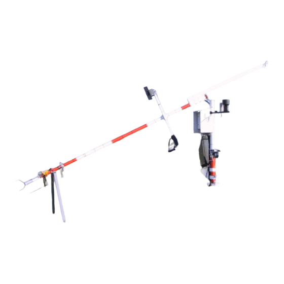
Installation Manual _________________________________________________________________ the building stages of a thunderstorm, before sufficient charge build- up has occurred that would generate a ground strike. Consequently, SA20M provides early warnings of potentially fatal single-event ground strikes. Tiltable Pole Mast DKP210AV_desert.jpg Figure 15 Tiltable Pole Mast DKP210AV-T DKP206AV-T and DKP210AV-T tiltable pole masts can be easily operated by one person when installing and maintaining the devices installed on the mast. -
Page 31: Foundation Set
The eye nuts for guy wires Wedge bolts for existing concrete block Plates with the nut for guy wire blocks Square plate for the mast base Foundation bolts Bar for the wedge bolts Key piece for the wedge bolts VAISALA _______________________________________________________________________ 29... -
Page 32: Guy Wires
Installation Manual _________________________________________________________________ Guy Wires The DKP206AV-T mast is delivered with one set of guy wires, whereas DKP210AV-T is delivered with two sets. Figure 17 below shows the contents of one set of guy wires and the accessories. The top fastener of the guy wires is mounted to the uppermost tube of the mast during installation. -
Page 33: Lightning Rod
Passive Lightning Rod and the Holders Winch The winch is easily installed to the pedestal tube. After erecting the mast, the winch should be removed from the pedestal tube and stored in a dry and warm place. Figure 19 Winch VAISALA _______________________________________________________________________ 31... -
Page 34: Obstruction Light
Installation Manual _________________________________________________________________ Obstruction Light An obstruction light is included in the mast delivery. Obelux Obstruction Light is a very low power obstruction light utilizing LED technology with a typical intensity of 17 cd. The obstruction light is supplied with 12 VDC nominal supply voltage. The stabilized output of the light makes it possible that the variations of the supply voltage do not affect to the light output. -
Page 35: Workstation With Midas Iv Software
Event Monitor. Data is archived for 30 days on hard disk and sent to other systems via serial port or as an FTP transfer via LAN. 0306-025 Figure 21 MIDAS IV Workstation and QCA101 VAISALA _______________________________________________________________________ 33... -
Page 36: Communication Accessory Enclosure Qca101
Installation Manual _________________________________________________________________ Communication Accessory Enclosure QCA101 Communication Accessory Enclosure QCA101 houses Transmitter WT501 equipped with Modem Module DMX501. Additionally, AC (mains) power supply, lightning protection device, and surge arresters are located in the enclosure. In Figure 21 on page 33 the QCA101 enclosure is shown beside the MIDAS IV PC. -
Page 37: Radio Modem
MAWS201MP and MIDAS IV PC. TM32 Radio modem features a watertight design for operation in unprotected environments common in field applications. TM32 features a fully synthesized multi-channel radio that allows operation on all frequencies in the supported VHF or UHF bands. VAISALA _______________________________________________________________________ 35... -
Page 38: Vhf Antennas
Installation Manual _________________________________________________________________ VHF Antennas The VHF antenna can be installed on the tripod (see Figure 24 below) or on the pole mast (see Figure 25 below). The frequency range is from 150 to 174 MHz. 0306-069 Figure 24 VHF Antenna on the Tripod 0306-016 Figure 25 VHF Antenna on the Mast... -
Page 39: Uhf Antennas
The UHF antenna can be installed on the tripod (see Figure 26 below) or on the pole mast (see Figure 27 below). The frequency range is from 410 to 470 MHz. 0310-066 Figure 26 UHF Antenna on the Tripod 0310-067 Figure 27 UHF Antenna on the Mast VAISALA _______________________________________________________________________ 37... -
Page 40: Mains Power Supply Module Qmp211
Installation Manual _________________________________________________________________ Mains Power Supply Module QMP211 The AC (mains) power supply module QMP211 is a switching power supply, which operates from the universal AC input of 100 to 240 VAC and 50/60 Hz. The output voltage is 12 VDC (2500 mA), which is used for powering the radio modem when it is connected to the MIDAS IV PC for configuring. -
Page 41: Product Nomenclature
MIDAS IV NT software for the MIDAS IV PC CT25KAM Ceilometer PWD11A Present weather detector SA20M Lightning detector OBL10-12 Obstruction light QMP202MP Power supply and connection unit QCA101 Communication accessory enclosure for PC end WT501+DMX501 Communication module VAISALA _______________________________________________________________________ 39... -
Page 42: Table 2 Cables Provided
Installation Manual _________________________________________________________________ Table 2 Cables Provided Code Common Name ZZ45202 PC/Handheld connection cable with DC connector, 5 m (15 ft) ZZ212024 WS425 Data/power cable for DKP206AV-T ZZ212915 WS425 Data/power cable for DKP210AV-T ZZ45214 AC cable, 5 m (15 ft) CT45300 AC supply cable for CT25KAM CT45298... -
Page 43: Installation Of The Mast
When the soil is frost-susceptible, make sure to always use the proper insulation. CAUTION For mast base installation, the soil bearing capacity has to exceed 45 kPa (940 pounds-force/sq. foot). VAISALA _______________________________________________________________________ 41... -
Page 44: Wind Measurement
Installation Manual _________________________________________________________________ Wind Measurement Allow sufficient clearance for the wind sensors, that is, the station should not be located next to a building or any other object that might affect the airflow. Refer to Figure 29 below and Figure 30 on page 43 that provide general guidelines for the mast location. -
Page 45: Air Temperature And Relative Humidity
The orifice of the gauge must be on a horizontal plane, open to the sky, and above the level of in-splashing and snow accumulation. In general, objects should not be closer to the gauge than a distance twice their height above the gauge orifice. VAISALA _______________________________________________________________________ 43... -
Page 46: Lightning Detection
Installation Manual _________________________________________________________________ In areas of homogeneous dense vegetation, the height of the vegetation should be kept below the gauge orifice level by regular mowing. Sites on a slope or on the roof of a building should be avoided. Also hard flat surfaces such as concrete should be avoided to prevent excessive in-splashing. -
Page 47: Present Weather Detection
100 m from all large buildings and other constructions that generate heat and/or obstruct precipitation droplets. The shade of trees should also be avoided as trees may cause changes in the microclimate. VAISALA _______________________________________________________________________ 45... -
Page 48: Figure 33 Recommended Location Of The Pwd11A
Although PWD11A is designed to withstand harsh weather conditions, there are locations where the environment places further demands on installation. Arctic and comparable environments may cause high snow and ice accumulation requiring additional heating. In this case, consult Vaisala or its authorized representative. 46 __________________________________________________________________ M210485EN-B... -
Page 49: Cloud Detection
- Ground the cable shield at both ends. - Use spike and overvoltage protection devices at both ends of field cables. Always make a detailed cabling and wiring plan. Data transmission lines from the outdoor sites to indoor devices have to be prepared VAISALA _______________________________________________________________________ 47... -
Page 50: Required Tools
If there has been any damage, contact Vaisala immediately. Also refer to the unpacking instructions of the weather station components in section Unpacking Instructions on page 87. -
Page 51: Figure 34 Contents Of The Mast Delivery (Part 1)
Lifting rod, ∅ 60 mm NOTE Figure 34 above and Figure 35 on page 50 only provide examples of the contents. The contents may vary depending on the model of the mast and on the selected options. VAISALA _______________________________________________________________________ 49... -
Page 52: Figure 35 Contents Of The Mast Delivery (Part 2)
Installation Manual _________________________________________________________________ 0303-025 Figure 35 Contents of the Mast Delivery (Part 2) The following numbers refer to Figure 35 above: Tilting support Pedestal tube, ∅ 100 mm Lower mast tube, ∅ 75 mm Assembly set: Guy wire fasteners (3 pcs) Guy assembly set (1 set) Hinge set (1 set) Lifting rod assembly set (1 set) -
Page 53: Foundation
To ease the orientation of the mast, the two-headed arrow is cut on the orientation plate. "N" should face north and "S" should face south to ensure the aiming of the weather station devices to the correct position. VAISALA _______________________________________________________________________ 51... -
Page 54: Figure 36 Dkp210Av-T Mast Orientation
Installation Manual _________________________________________________________________ 0207-064 Figure 36 DKP210AV-T Mast Orientation NOTE The transformation for the dimensions in Figure 36 above: 5 m ≈ 16.4 ft. 6 m ≈ 19.7 ft. 52 __________________________________________________________________ M210485EN-B... -
Page 55: Figure 37 Dkp206Av-T Mast Orientation
Chapter 3 ______________________________________________________ Installation of the Mast 0207-065 Figure 37 DKP206AV-T Mast Orientation NOTE The transformation for the dimensions in Figure 37 above: 4 m ≈ 13.1 ft. VAISALA _______________________________________________________________________ 53... -
Page 56: Concrete Foundation Types
Installation Manual _________________________________________________________________ Concrete Foundation Types The tiltable pole mast can be mounted on a new or an existing concrete pad. The pole mast is fixed to the concrete pad with foundation bolts. When preparing a new concrete pad, fasten the foundation bolt assembly simultaneously with the concrete pour. -
Page 57: Figure 39 Concrete Pad For Guy Wires (Dimensions In Mm)
The transformation for the dimensions in Figure 39 above. 40 mm ≈ 1.57 in. 50 mm ≈ 1.97 in. 240 mm ≈ 9.45 in. 400 mm ≈ 15.75 in. 600 mm ≈ 23.62 in. 800 mm ≈ 31.50 in. VAISALA _______________________________________________________________________ 55... -
Page 58: Making A New Concrete Pad
Installation Manual _________________________________________________________________ Making a New Concrete Pad NOTE The transformation for the dimensions in this section: 10 mm ≈ 0.39 in. 12 mm ≈ 0.47 in. 40 mm ≈ 1.57 in. 50 mm ≈ 1.97 in. 70 mm ≈ 2.76 in. 150 mm ≈... -
Page 59: Figure 41 Foundation Assembly For The Mast Base
58) should be at the same height as the top of the finalized concrete pad. Also check the correct alignment of the foundation assembly with the orientation plate (number 4 in Figure 42 on page 58). "N" should face north and "S" should face south. VAISALA _______________________________________________________________________ 57... -
Page 60: Figure 42 Foundation Assemblies For A New Concrete Pad
Installation Manual _________________________________________________________________ 0207-062 Figure 42 Foundation Assemblies for a New Concrete For the guy wires, fix the foundation bolt (number 2 in Figure 42 above) to the plate with a nut (3). Fix the eye nut (1) to the other end of the foundation bolt. -
Page 61: Using An Existing Concrete Pad
Hammer the wedge bolts (4) down using the provided bar (2). Screw the foundation bolts (1) to the wedge bolts and tighten the screws properly. Fill the remaining space of the holes with a suitable compound. Start assembling the mast after the compound is dry. VAISALA _______________________________________________________________________ 59... -
Page 62: Assembling The Mast
Installation Manual _________________________________________________________________ Assembling the Mast Work Order To assemble the mast, follow the work order below: Attach the 2-meter-high pedestal tube to the concrete foundation. Lift the lower base of the mast to the upper end of the pedestal tube and assemble the hinge axle. -
Page 63: Installing The Pedestal Tube
Install the nuts with the washers and spring washers to the foundation bolts. Refer to Figure 45 below. 0303-029 Figure 45 Pedestal Tube Attachment VAISALA _______________________________________________________________________ 61... -
Page 64: Figure 46 Pedestal Tube Adjustment With Water Level
Installation Manual _________________________________________________________________ The following numbers refer to Figure 45 on page 61: Foundation bolt Spring washers, under and above the plate Washers, under and above the plate Nuts, under and above the plate NOTE The delivered washers may differ from the ones shown in Figure 45 on page 61. -
Page 65: Connecting The Lowest Mast Tube To The Pedestal Tube
Thread the Allen bolt (4) with the washers (2 and 3) to either end of the axle. Lift the mast end (3) on the hinge (1) and install the axle (2), see Figure 48 below. 0303-032 Figure 48 Hinge Axle Installation VAISALA _______________________________________________________________________ 63... -
Page 66: Connecting The Lifting Rod To The Mast
Installation Manual _________________________________________________________________ Thread the other Allen bolt to the axle and tighten both ends with the Allen key. Connecting the Lifting Rod to the Mast The delivery contains the lifting rod that is used with the winch to erect and tilt the upper mast assembly. The clamps are preinstalled at the factory to the lifting rod and to the lowest mast tube. -
Page 67: Connecting The Guy Wire Set To The Mast
36 on page 52 and Figure 37 on page 53. After installing the lightning rod, you should align the lightning rod holders to the same direction with the insulated guy wire, see Figure 55 on page 69. VAISALA _______________________________________________________________________ 65... -
Page 68: Assembling The Mast Tubes
Installation Manual _________________________________________________________________ 0303-035 Figure 51 Guy Wire Attachment Assembling the Mast Tubes The upper mast tube(s) has the O-ring (number 1 in Figure 52 below) installed on the tube. For connecting the mast tubes, use lubricant to make the O-ring slippery and simply slide the mast tubes together. -
Page 69: Assembling The Lightning Rod
Lightning Rod Installation to the Mast Secure the holders to the mast with the bolts in the clamps (4). Check that the dimensions for the installed lightning rod are as illustrated in Figure 54 on page 68. VAISALA _______________________________________________________________________ 67... -
Page 70: Connecting The Grounding Cable To The Insulated Guy Wire
Installation Manual _________________________________________________________________ 0303-038 Figure 54 Dimensions (in mm) for Lightning Rod Assembly on the Mast NOTE The transformation for the dimensions in Figure 54 above: 20 mm ≈ 0.79 in. 150 mm ≈ 5.91 in. 350 mm ≈ 13.8 in. 440 mm ≈... -
Page 71: Routing The Device Cables
It is also important to attach the cables to the mast with the cable ties. The recommended distance between the cable ties is from 30 to 40 cm (11 to 16 in.). VAISALA _______________________________________________________________________ 69... -
Page 72: Erecting The Mast
Installation Manual _________________________________________________________________ Erecting the Mast NOTE Before erecting the mast, refer to the installation instructions of the additional sensors and devices. It is important to aim the sensors correctly before erecting the mast. Before erecting the mast, check that the bolts of the top fastener are tight. -
Page 73: Figure 57 Securing The Clamp Of The Winch
(2) to the plate lug (3) of the pedestal plate. Make sure that the end of the wire (1) with the spring clip points east (when installing in the northern hemisphere). 0310-059 Figure 58 Lower Cable Lead VAISALA _______________________________________________________________________ 71... -
Page 74: Figure 59 Attaching The Spring Clip
Installation Manual _________________________________________________________________ Clip the spring clip (number 1 in Figure 59 below) to the plate lug (2) of the lifting rod. 0310-060 Figure 59 Attaching the Spring Clip Take a good grasp on the handle and turn it clockwise to erect the mast. -
Page 75: Securing The Hinge
Always assemble the washers under the spring washers to prevent the paint from being damaged. 0303-045 Figure 60 Bolts and Washers for Securing the Hinge The following numbers refer to Figure 60 above: Allen bolt Spring washer Washer VAISALA _______________________________________________________________________ 73... -
Page 76: Connecting The Guy Wires To The Concrete Pads
Installation Manual _________________________________________________________________ Connecting the Guy Wires to the Concrete Pads WARNING Always wear gloves when handling the guy wires. 0303-046 Figure 61 Guy Wires Follow the procedure below to connect the guy wires to the concrete pads: Connect the guy wires 2 and 3 as instructed in step a. below and connect the guy wire 1 as instructed in step b. -
Page 77: Figure 62 Connecting The U-Bolt To The Eye Bolt
(4) is used as with guy wires 2 and 3. 0303-047 Figure 63 Guy Wire 1 Attachment NOTE The additional bow shackle (number 2 in Figure 63 above) may differ from the one shown in the figure. VAISALA _______________________________________________________________________ 75... -
Page 78: Figure 64 Securing The Guy Wires
Installation Manual _________________________________________________________________ Secure the guy wires with the provided wire rope clips (number 3 in Figure 64 below). Place the wire rope clips on the wire so that the forged, grooved part clamps the wire coming from the mast (the tension side) and the U-bolt clamps down on the end- most section of the wire. -
Page 79: Equipment Grounding And Lightning Protection
It is recommended to use copper (Cu). WARNING Failure to provide proper grounding may result in personnel injury or death from electrical shock and may severely damage equipment. VAISALA _______________________________________________________________________ 77... -
Page 80: Figure 66 Location Of The Grounding Rods And An Optional Grid, The Arrow Points To The Mast Tilt Direction
Installation Manual _________________________________________________________________ WARNING Lightning protection is required to prevent personnel injury and equipment damage due to direct lightning strikes and lightning- induced current surges. 0306-035 Figure 66 Location of the Grounding Rods and an Optional Grid, the Arrow Points to the Mast Tilt Direction The following numbers refer to Figure 66 above. -
Page 81: Table 3 Examples Of Soil Resistivities, Ohm-Meters
Well graded gravel, gravel sand mixtures 600 ... 1 000 Due to the above reasons and variations, the grounding accessories presented in this manual (rods, connectors, etc.) are only examples of the proper ones, thus recommended to be supplied locally. VAISALA _______________________________________________________________________ 79... -
Page 82: Equipment Grounding
Installation Manual _________________________________________________________________ 0303-049 Figure 67 Ground Rod Installation The following numbers refer to Figure 67 above: Access well Grounding rod Compression lug Grounding cable Equipment Grounding The equipment grounding cable is connected to the equipment ground system (rod or other) from the one main grounding point, which is normally a grounding bar located underneath the main system enclosure. -
Page 83: Figure 68 Installing The Grounding Bar
2 meters. The 2-meter cable can be obtained by first cutting the connection cable of the lightning rod to the correct length. The rest of the cable can be used for grounding the equipment. The original length of the cable is 15 m. VAISALA _______________________________________________________________________ 81... -
Page 84: Figure 69 Connecting The Grounding Cables To The Bar
Installation Manual _________________________________________________________________ 0207-095 Figure 69 Connecting the Grounding Cables to the Bar The following numbers refer to Figure 69 above. Grounding cable Clamp Grounding bar It is recommended to protect the grounding cable on the surface of the concrete pad as illustrated in Figure 70 below. This applies only when the mast is installed on an existing concrete pad. -
Page 85: Grounding Of The Lightning Rod
The lightning rod is grounded near the concrete pad for the insulated guy wire, see Figure 71 below. 0303-051 Figure 71 Grounding of the Lightning Rod The following numbers refer to Figure 71 above. Clamp Cable from the lightning rod Guy wire attachment VAISALA _______________________________________________________________________ 83... -
Page 86: Tilting The Mast
Installation Manual _________________________________________________________________ Tilting the Mast You need to tilt the mast, for example, when devices installed on the upper assembly need to be aligned. The following sections provide you with instructions on tilting the mast. Disconnecting and Securing the Guy Wire Disconnect the guy wire 1 that is on the opposite side of the mast to the hinge. -
Page 87: Figure 72 Tilted Mast With Tilting Support
Chapter 3 ______________________________________________________ Installation of the Mast 0303-052 Figure 72 Tilted Mast with Tilting Support VAISALA _______________________________________________________________________ 85... - Page 88 Installation Manual _________________________________________________________________ This page intentionally left blank. 86 __________________________________________________________________ M210485EN-B...
-
Page 89: Installation Of The Weather Station Components To The Mast
Unpacking Instructions When you have received the delivery, check that the sensors have not been damaged during transportation. NOTE Store all the sensors and other devices in their shipping boxes until you install them to the mast. VAISALA _______________________________________________________________________ 87... -
Page 90: Weather Station Structure
Installation Manual _________________________________________________________________ Weather Station Structure An example of the fully installed MAWS201MP weather station structure is shown in Figure 73 below. NOTE The mast may differ from the one presented in the figures. 0306-036 Figure 73 Mechanical Structure of MAWS201MP 88 __________________________________________________________________ M210485EN-B... -
Page 91: Mounting The Radiation Shield
The radiation shield protects the logger tube and power supply and communication unit, which is equipped with AC/DC power supplies, battery regulator, backup battery, and communication devices. The rear view of the radiation shield is shown in Figure 74 below. 0306-037 Figure 74 Mounting the Radiation Shield VAISALA _______________________________________________________________________ 89... -
Page 92: Mounting The Logger Tube
Installation Manual _________________________________________________________________ The following numbers refer to Figure 74 on page 89. Two installation screws for attaching the logger tube to the radiation shield Four installation screws for attaching the power supply and communication unit to the radiation shield Two attachment brackets Eight installation bolts for assembling the brackets to the mast... -
Page 93: Mounting The Qmp202Mp Unit
Refer to number 2 in Figure 74 on page 89 for the location of the mounting holes. Secure the power supply unit with four bolts and washers as illustrated in Figure 77 on page 92. VAISALA _______________________________________________________________________ 91... -
Page 94: Mounting The Obstruction Light
Installation Manual _________________________________________________________________ After installing other devices to the mast, connect the cables to the QMP202MP unit as instructed in section Connecting the Cables on page 106. 0306-040 Figure 77 Mounting the Bolt and Washer for Power Supply Unit Mounting the Obstruction Light The obstruction light is installed to the holder that is installed between the lightning rod holders. -
Page 95: Installing Sensors
It is also important to attach the cables to the mast with the cable ties. CAUTION Be careful not to pinch cables during installation. CAUTION When connecting cables, be careful so that the connector pins do not bend. VAISALA _______________________________________________________________________ 93... -
Page 96: Mounting Qma102M Sensor Arm
(4). Mounting Ultrasonic Wind Sensor The ultrasonic wind sensor is mounted vertically to the Vaisala sensor adapter with the transducers facing up. To install the wind sensor to the mast with the sensor adapter, do the following (the numbers refer... -
Page 97: Figure 80 Installing Ultrasonic Wind Sensor
Chapter 4 _________________________ Installation of the Weather Station Components to the Mast CAUTION Save the container and all the packaging materials. Always ship the Vaisala Ultrasonic Wind Sensor in its custom shipping container. Otherwise, you will void the warranty. 0211-099... -
Page 98: Figure 81 A Sketch Of Magnetic Declination
Installation Manual _________________________________________________________________ NOTE Do not remove the plastic cover from the end of the pole mast. Attach the sensor adapter to the pole mast tube so that when the mast is erected, the transducer head marked with "N" is closely aligned for north and the transducer head marked with "S"... -
Page 99: Figure 82 Correctly Aligned Ultrasonic Wind Sensor
"N" and "S" are aligned to north and south when the mast is erected. Tighten the mounting clamp. Erect the mast to the vertical position and check the alignment again until the sensor is correctly aligned with the required accuracy. VAISALA _______________________________________________________________________ 97... -
Page 100: Figure 83 Ultrasonic Wind Sensor Mounted To The Mast
Installation Manual _________________________________________________________________ WARNING To protect personnel and the wind sensor, a lightning rod must be installed with the tip several feet above the wind sensor. The rod must be properly grounded, compliant with all applicable safety regulations. Attach the cables to the mast with the cable ties. Connect the signal cable to the correct connector on the logger tube, see section Connecting Sensors to the Logger Tube on page 108. -
Page 101: Mounting The Sensor Arm
0306-044 Figure 84 Sensor Arm Installation to the Mast The following numbers refer to Figure 84 above. Mounting piece for the lightning detector Mounting bracket on the sensor arm Mounting notch for the present weather sensor VAISALA _______________________________________________________________________ 99... -
Page 102: Mounting Present Weather Sensor
Installation Manual _________________________________________________________________ Mounting Present Weather Sensor To install the Present Weather Sensor to the sensor arm that is installed to the mast, follow the procedure below: CAUTION Do not touch the rain detector plate. Take special care to prevent it from being hit. -
Page 103: Mounting The Lightning Detector
Connect the DC power/signal cable to the connector on SA20M, see Figure 87 on page 102 and the other end to the correct connector on the QMP202MP unit, see section Connecting Sensors to QMP202MP on page 107. VAISALA ______________________________________________________________________ 101... -
Page 104: Figure 87 Connecting The Data Cable
Installation Manual _________________________________________________________________ 0306-047 Figure 87 Connecting the Data Cable Connect the provided grounding cable to the earth screw on the bottom of SA20M and secure with the finger screw, refer to Figure 88 below. The other end of the grounding cable is attached to the same grounding point as other equipment. -
Page 105: Mounting The Ceilometer
(number 1 in Figure 90 on page 104). Both brackets are secured to the mast with four bolts (2). Measure that the distance between the upper end of the ceilometer support and the plate of the mast tube is approximately 450 mm (17.7 in.). VAISALA ______________________________________________________________________ 103... -
Page 106: Figure 90 Installing The Ceilometer Support
Installation Manual _________________________________________________________________ Align the ceilometer support north in the northern hemisphere (south in the southern hemisphere) to ensure that the optical window points away from the sun. To help the alignment, there is an arrow on the support. 0306-050 Figure 90 Installing the Ceilometer Support Open the delivery box of the ceilometer. -
Page 107: Figure 91 Installing The Ceilometer To The Support
Coil any excess slack of the cables and clamp them to the hooks under the support. Attach the cables to the mast with the cable ties. Verify the installation as instructed in section Verification on page 122. VAISALA ______________________________________________________________________ 105... -
Page 108: Connecting The Cables
Installation Manual _________________________________________________________________ 0306-020 Figure 93 CT25KAM Installed on the Ceilometer Support Connecting the Cables 0310-061 Figure 94 Connectors on the QMP202MP Unit The following number refer to Figure 94 above:: Grounding connector 106 _________________________________________________________________ M210485EN-B... -
Page 109: Connecting Sensors To Qmp202Mp
Sensors, Cables, and the Connectors on QMP202MP Sensor Cable Connector on QMP202MP Present Weather Detector Connected PWD11A PWD11A to sensor Ceilometer CT25KAM CT45298 CT25KAM CT45300 AC to CT25KAM Lightning Detector SA20M ZZ45215 SA20M Ultrasonic Wind Sensor WS425 ZZ212024 Wind Power VAISALA ______________________________________________________________________ 107... -
Page 110: Connecting Sensors To The Logger Tube
Installation Manual _________________________________________________________________ Connecting Sensors to the Logger Tube The sensors and the applicable cables that are connected to the upper plate of the logger tube are listed in Table 5 below. Table 5 Sensors, Cables, and the Connectors on QME101M Sensor Cable Connector on Logger Tube... -
Page 111: Connecting The Grounding Cable To Qmp202Mp
Fix the grounding cable to the pedestal tube with cable ties. To connect the other end of the grounding cable, refer to section Equipment Grounding on page 80. Connecting Communication Cable to QMP202MP The communication cable is connected to the Field data connector on the QMP202MP unit. VAISALA ______________________________________________________________________ 109... -
Page 112: Securing And Protecting The Cables
Installation Manual _________________________________________________________________ Securing and Protecting the Cables After you have connected the cables from the sensors to the QMP202MP unit, secure all the cables to the mast with cable ties, refer to Figure 96 below. 0306-055 Figure 96 Securing Cables to the Mast Near the hinge you should protect the cables with the provided spiral to avoid possible damages to cables when the mast is tilted and erected. -
Page 113: Storing The Tools For Future Use
0306-066 Figure 98 Connecting the Handheld Terminal Installations inside QMP202MP Normally all devices inside the QMP202MP unit are fully installed at the factory, and there is no need to open the door of the enclosure. VAISALA ______________________________________________________________________ 111... -
Page 114: Installing Optional Radio Communication
Installation Manual _________________________________________________________________ Installing Optional Radio Communication NOTE The radio modem in your system may differ from the one shown in the figures of this section. Mounting the Antenna to the Mast For mounting the antenna, select a desired height (preferably as high as possible). -
Page 115: Figure 100 Uhf Antenna Assembly
(number 3 in Figure 101 on page 114) on the mounting piece. The notch (4) at the end of the arm must face up. Secure the antenna arm with the hand screw (2). Mount the antenna (5) to the antenna arm and secure with the hand screw. VAISALA ______________________________________________________________________ 113... -
Page 116: Configuring The Radio Modems
NOTE This section applies only to the radio modem models TM32 and RFM96W delivered by Vaisala. Before installing a radio modem to the sensor arm or to the tripod, you need to configure the radio modems. It is most convenient to configure both radios in a row once you have stopped the MIDAS IV software. -
Page 117: Setting Up The Radio Modems
Before deployment, the radio modems must be configured. Setting Up the Radio Modems The radio modem settings are done with the PC/DOS software RFMCONFD that is installed on the MIDAS IV PC. The program is started in the TACMET Configuration Wizard window. VAISALA ______________________________________________________________________ 115... -
Page 118: Figure 102 Connecting A Radio Modem To A Pc For Configuration
Installation Manual _________________________________________________________________ 0011-044 Figure 102 Connecting a Radio Modem to a PC for Configuration Disconnect the radio modem from outdoors, if already installed, and place it near the MIDAS IV PC. Shut all MIDAS IV programs on the MIDAS IV PC, and when applicable disconnect the MIDAS IV PC from the QCA101 unit. -
Page 119: Figure 103 Model Information Window
To set the radio modem configuration, select Configure - Settings. For the correct settings, refer to Table 6 on page 118 and Figure 104 below. Finally, to approve the settings, click the OK button. 0306-061 Figure 104 Radio Modem Settings VAISALA ______________________________________________________________________ 117... -
Page 120: Figure 105 Configuring Channel Frequencies
Installation Manual _________________________________________________________________ Table 6 Radio Modem Settings Value Setting Baud Rate 4800 Parity None RS-485 Delay Break to Command Mode Packet Switched Digipeater Delay 0.00 Local Node Non-Repeating Link Rate 4800 Retries CSMA Monitor Scrambling Digisquelch Moderate TX ACK T/O Local Addr Dest. -
Page 121: Selecting The Active Channel
Shut down all MIDAS IV programs on the MIDAS IV PC. Click the Radio Modem button in the TACMET Configuration Wizard window to start the configuration software. Enlarge the window by pressing ALT+ENTER. In the Configure menu, select Load. VAISALA ______________________________________________________________________ 119... -
Page 122: Installing A Radio Modem To The Sensor Arm
Installation Manual _________________________________________________________________ Follow the instructions on the screen to select the appropriate COM port (usually COM1) and to connect the power supply when asked to. When the Model information window appears, click the OK button to proceed. To set the active channel, select Configure - Settings. Under Channel Select, open the list of the channels by clicking the green arrow. -
Page 123: Figure 107 Installing A Radio Modem To Sensor Arm
Figure 95 on page 107. 0310-047 Figure 108 Connecting the Data/Power Cable between a Radio Modem and Logger Tube Connect the antenna cable (number 1 in Figure 109 on page 122) to the BNC connector (2) on a radio modem (3). VAISALA ______________________________________________________________________ 121... -
Page 124: Verification
Installation Manual _________________________________________________________________ 0310-048 Figure 109 Connecting the Antenna Cable Verification To verify the system, power it up: Connect the battery connector inside QMP202MP. Connect the AC cable to power outlet. Turn the power switch ON inside QMP202MP. Ceilometer CT25KAM After switching the AC (mains) power on, you can verify the operation of CT25KAM Ceilometer with the status LED, see Table 7 below. -
Page 125: Lightning Detector Sa20M
If you do not receive data to MIDAS IV PC, open the door of the QMP202MP enclosure and check that the green light blinks on the transmitter. Radio Modem Confirm by checking the LEDs of the modem that the modem is powered and it is sending and receiving data. VAISALA ______________________________________________________________________ 123... - Page 126 Installation Manual _________________________________________________________________ This page intentionally left blank. 124 _________________________________________________________________ M210485EN-B...
-
Page 127: Installing Indoor Components
128 MB RAM Hard Disk Space 200 MB File System NTFS Drives CD-ROM Drive Serial Ports 1 free serial port System Time GMT/UTC time 1) With Service Pack 3 2) Minimum installation requires 50 MB hard disk space VAISALA ______________________________________________________________________ 125... -
Page 128: Installation Procedure
NOTE Usually you will not need to install the MIDAS IV software, as it is already installed at Vaisala. When the MIDAS IV software is launched in the Windows startup automatically, you can proceed to section MIDAS IV TACMET Configuration on page 127. -
Page 129: Midas Iv Tacmet Configuration
The optional Dial-up sub-menu has two items: Use Dial-up and Configuration software. Use Dial-up-item is used to enable/disable dial-up connection, for example, satellite connection. Configuration software -item is used to select an application for configuration of the dial-up connection. VAISALA ______________________________________________________________________ 127... -
Page 130: System Parameters Tab
Installation Manual _________________________________________________________________ Table 9 below explains the Configuration Wizard Buttons. Table 9 Explanation of Configuration Wizard Buttons Button Explanation Radio Modem Opens Radio Modem Configuration program Dial-up Opens optional Dial-Up Manager Silence MAWS/ Silences MAWS Enable MAWS Asks which radio channel to use and then enables MAWS Sensor Terminal Opens Sensor Terminal application... -
Page 131: Weather View Tab
Weather View Tab With the Weather View tab, you can configure the amount and the order of the displays in Weather View. 0310-033 Figure 111 Weather View Tab NOTE Normally there is no need to modify the display settings. VAISALA ______________________________________________________________________ 129... -
Page 132: Qca101 Communication Module Installation
Installation Manual _________________________________________________________________ QCA101 Communication Module Installation Always install the communication module indoors as close to the MIDAS IV PC as possible. That is to ensure trouble-free data transfer via the RS-232 line to the MIDAS IV PC. NOTE All the connections inside the QCA101 unit are made at the factory. Normally there is no need to open the QCA101 unit during installation. -
Page 133: Ac (Mains) Power
Connect the other end of the cable to the QCA101 unit and secure with the screws. Communication Connection to the QCA101 Unit The communication connection (landline connection) for the modem uses a twisted pair cable. The cable is connected to the Field cable connector. VAISALA ______________________________________________________________________ 131... -
Page 134: Installing Optional Radio Communication
Installation Manual _________________________________________________________________ Installing Optional Radio Communication CAUTION Only operate the radio modem with the antenna or appropriate substitute (dummy load) connected. NOTE The radio modem in your system may differ from the one shown in the figures of this section. Follow the procedure below to set up and connect the radio modem to MIDAS IV PC: Before installing the radio modem to the tripod, select the same... -
Page 135: Figure 114 Uhf Antenna In Tripod
UHF Antenna in Tripod Place the correctly configured radio modem (number 4 in Figure 115 below) to the adapter that is mounted on the leg of the tripod. 0310-064 Figure 115 Connecting the Radio Modem to PC VAISALA ______________________________________________________________________ 133... - Page 136 Installation Manual _________________________________________________________________ Connect the appropriate antenna cable and data/power cable (number 3 in Figure 115 on page 133) to the radio modem (4). Connect the PC cable (2) to the PC (1). Connect the power supply (6) to the DC connector (5) of the PC cable (2).
-
Page 137: Chapter 6 Technical Data
1 min Relative humidity (QMH101M) 10 s 1 min Air pressure (PMT16A) 10 s 1 min Precipitation (QMR101M) 1 min 1 min Lightning (SA20M) Sky condition (CT25KAM) 30 s 30 s Present weather (PWD11A) 30 s 30 s VAISALA ______________________________________________________________________ 135... -
Page 138: Specifications
Installation Manual _________________________________________________________________ Specifications Weather Station MAWS201MP Table 13 MAWS201MP Specifications Property Description/Value AC power consumption 260 VA, max. 2.3 A @ 115 VAC 1.15 A @ 230 VAC Battery backup time 4 h, at minimum (excluding PC equipment; optional UPS for PC equipment) Communication range with the 20 km (12 mi.) with AWG 22 cable QCA101 unit equipped with... -
Page 139: Logger Qml102T
-50 ... +70 °C (-58 ... 158 °F) Humidity 0 ... 100 %RH Emissions CISPR 22 class B (EN55022) ESD immunity IEC 61000-4-2 RF field immunity IEC 61000-4-3 EFT immunity IEC 61000-4-4 Surge (lightning pulse) IEC 61000-4-5 Conducted RF immunity IEC 61000-4-6 VAISALA ______________________________________________________________________ 137... -
Page 140: Power Supply And Connection Unit Qmp202Mp
Installation Manual _________________________________________________________________ Power Supply and Connection Unit QMP202MP Table 15 Battery Regulator QBR101 Specifications (Inside QMP202MP) Property Description/Value Maximum input voltage (SMPS and 30 VDC Solar Panel inputs) Maximum input current (SMPS) Solar panel input 55 W max. Recommended input voltage from 16 VDC SMPS input Max. -
Page 141: Table 16 Power Supply Unit Bwt36Sxz Specifications (Inside Qmp202Mp)
Operating temperature range -40 ... +60 °C (-40 ... 140 °F) Weight with chassis 250 g (8.8 oz) Approvals UL 1950 CSA 234 (IEC 950) VDE0805 EN 60959 (IEC 950) CE - EMC 89/336 EEC - LVD 73/23 EEC VAISALA ______________________________________________________________________ 139... -
Page 142: Table 17 Power Supply Unit Bwc15Sxz Specifications (Inside Qmp202Mp)
Installation Manual _________________________________________________________________ Table 17 Power Supply Unit BWC15SXZ Specifications (Inside QMP202MP) Property Description/Value Output power 75 W Operating principle SMPS Input voltage range 85 … 264 VAC Frequency range 47 … 440 Hz Input current on full load: 100 VAC 1.7 A 230 VAC 0.9 A... -
Page 143: Digital Transmitter Wt501
0.4 kg (14.1 oz) Operating temperature -40 ... +60 °C (-40 ... 140 °F) Storage temperature -50 ... +70 °C (-58 ... 158 °F) Humidity operating and 2 ... 95 %RH storage CE compliant Vibration According to MIL-STD-167-1 VAISALA ______________________________________________________________________ 141... -
Page 144: Modem Module Dmx501
Installation Manual _________________________________________________________________ Modem Module DMX501 Table 20 DMX501 Specifications Property Description/Value Modem chip 73K324L Modem chip crystal frequency 11.0592 MHz USART clock frequency 11.0592 MHz / 2 Register access Operated through an 8-bit bus interface Connection 2-wire Point-to-point line or multidrop modem network Modem protocols V.21, 300 bps FSK... -
Page 145: Handheld Terminal Qmd101M
191 x 102 x 33 mm (7.5 x 4.0 x 1.3 in) without case expansion ring Weight 450 g (1 lb) Operating temperature -20 ... +70 °C (-4 ... 158 °F) Operating humidity Max. 90 %RH non-condensing VAISALA ______________________________________________________________________ 143... -
Page 146: Heated Ultrasonic Wind Sensor Ws425
Installation Manual _________________________________________________________________ Heated Ultrasonic Wind Sensor WS425 Table 22 WS425 Specifications Property Description/Value Sensor type Ultrasonic 100 kHz Fully compensated for temperature, humidity, and altitude. Measuring range 0 ... 56 m/s (0 ... 125 mph, 0 ... 107 knots) 0 …... -
Page 147: Pressure Sensor Pmt16A
(31 in Sensitivity 0.2 mm (1/128 in) Capacity 144 mm/h (5.7 in/h) Accuracy < 24 mm/h < ± 5 % < 120 mm/h < ± 10 % Material UV stabilized plastic Cable Included Weight 380 g (13.4 oz) VAISALA ______________________________________________________________________ 145... -
Page 148: Ceilometer Ct25Kam
Installation Manual _________________________________________________________________ Ceilometer CT25KAM Table 26 CT25KAM Specifications Property Description/Value Measurement range 0 ... 25 000 ft (0 ... 7.5 km) 25 000 ft acquisition time 15 s Accuracy (against hard ± 2 % ± 1/2 × [resolution] target) Resolution 50 ft Number of layers... -
Page 149: Present Weather Detector Pwd11A
-40 ... +55 °C (-40 ... 131 °F) range Operating humidity range Up to 100 %RH Dimensions w × d × h 720 × 320 × 220 mm (28.3 × 12.6 × 8.66 in) Weight 2.8 kg (6.17 lb.) VAISALA ______________________________________________________________________ 147... -
Page 150: Lightning Detector Sa20M
Installation Manual _________________________________________________________________ Lightning Detector SA20M Table 28 SA20M Specifications Parameter Description/Value Types of strikes detected Cloud-to-cloud Cloud-to-ground Maximum processing rate 5 000 strikes per minute Operational Limits Range 0 ... 90 km (0 ... 50 nmi.) Bearing 0º ... 360º Resolution: Range 2 km (1 nmi.) -
Page 151: Tiltable Pole Mast
Pedestal tube and hinge Corrosion-resistant powder coating Aluminum parts Anodized and painted Steel parts Galvanized Stainless steel parts Uncoated Mast concrete base Soil bearing capacity must exceed 45 kPa Weight (pole with winch) 125 kg (276 lb) VAISALA ______________________________________________________________________ 149... -
Page 152: Table 31 Dkp206Av-T Specifications
Installation Manual _________________________________________________________________ Table 31 DKP206AV-T Specifications Property Description/Value Height 6 m (19.7 ft) Maximum wind speed With one set of guy wires 65 m/s (126 knots) Diameter Lowest section (0 ... 1.9 m) 100 mm (3.94 in) Second section (1.9 ... 4.9 m) 75 mm (2.95 in) Highest section 63 mm (2.48 in) -
Page 153: Tm32 Radio Modem
-67 ... 185 °F (-55 ... +85 °C) Vibration/Shock IEC 68-2-55 Enclosure IEC 144/855420 IP 66 Dust-tight and watertight. Dimensions w × d × h 70 × 23 × 132 mm (2.75 × 0.9 × 5.2 in) Weight 255 g (9 oz) excluding cable VAISALA ______________________________________________________________________ 151...
Need help?
Do you have a question about the MAWS201MP TACMET and is the answer not in the manual?
Questions and answers