Sign In
Upload
Manuals
Brands
Vaisala Manuals
Weather Station
TACMET MAWS201MP
Vaisala TACMET MAWS201MP Manuals
Manuals and User Guides for Vaisala TACMET MAWS201MP. We have
2
Vaisala TACMET MAWS201MP manuals available for free PDF download: Installation Manual, User Manual
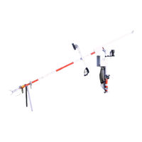
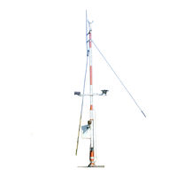
Vaisala TACMET MAWS201MP Installation Manual (153 pages)
Weather Station for Pole Mast Installations
Brand:
Vaisala
| Category:
Weather Station
| Size: 10.26 MB
Table of Contents
Table of Contents
3
Chapter 1 General Information
11
About this Manual
11
Contents of this Manual
11
Feedback
12
Safety
12
General Safety Considerations
12
Product Related Safety Precautions
12
ESD Protection
15
Trademarks
15
License Agreement
15
Warranty
16
Technical Support
16
Chapter 2 Product Overview
17
Introduction to TACMET MAWS
17
Figure 1 TACMET MAWS System
18
MAWS Operating Software
19
Radiation Shield
19
Figure 2 Radiation Shield
19
AWS Logger QML102T
20
Figure 3 Logger QML102T
20
Power Supply and Connection Unit QMP202MP
21
Backup Battery
21
Battery Regulator QBR101
21
Power Supply Unit BWC15SXZ
21
Power Supply Unit BWT36SXZ
22
Power Strip QPS101
22
Figure 4 Power Strip QPS101
22
Transmitter WT501
23
Modem Module DMX501
23
Figure 5 Transmitter WT501
23
Figure 6 Modem Module DMX501
23
Ultrasonic Wind Sensor WS425
24
Figure 7 Ultrasonic Wind Sensor WS425
24
Air Temperature and Relative Humidity Sensor QMH101M
25
Figure 8 Installation Adapter for Ultrasonic Wind Sensors
25
Figure 9 QMH101M with Radiation Shield
25
Pressure Sensor PMT16A
26
Figure 10 Pressure Sensor PMT16A
26
Rain Gauge QMR101M
27
Ceilometer CT25KAM
27
Figure 11 Rain Gauge QMR101M
27
Figure 12 Ceilometer CT25KAM
27
Present Weather Detector PWD11A
28
Figure 13 Present Weather Detector PWD11A
28
Lightning Detector SA20M
29
Figure 14 Lightning Detector SA20M
29
Tiltable Pole Mast
30
Figure 15 Tiltable Pole Mast DKP210AV-T
30
Figure 16 Foundation Set for DKP206AV
31
Foundation Set
31
Figure 17 Guy Wires Set
32
Guy Wires
32
Figure 18 Passive Lightning Rod and the Holders
33
Figure 19 Winch
33
Lightning Rod
33
Winch
33
Figure 20 Obstruction Light with the Power Cable
34
Obstruction Light
34
Workstation with MIDAS IV Software
35
Figure 21 MIDAS IV Workstation and QCA101
35
Communication Accessory Enclosure QCA101
36
Handheld Terminal QMD101M
36
Figure 22 QMD101M Handheld Terminal
36
Radio Modem
37
Figure 23 TM32 Radio Modem
37
Figure 24 VHF Antenna on the Tripod
38
Figure 25 VHF Antenna on the Mast
38
VHF Antennas
38
Figure 26 UHF Antenna on the Tripod
39
Figure 27 UHF Antenna on the Mast
39
UHF Antennas
39
Figure 28 Mains Power Supply Module QMP211
40
Mains Power Supply Module QMP211
40
Product Nomenclature
41
Table 1 TACMET MAWS201MP Nomenclature
41
Table 2 Cables Provided
42
Chapter 3 Installation of the Mast
43
Siting Criteria
43
Soil Evaluation
43
Wind Measurement
44
Figure 29 Recommended Mast Location in Open Area
44
Air Temperature and Relative Humidity
45
Precipitation
45
Figure 30 Recommended Mast Length on Top of a Building
45
Lightning Detection
46
Figure 31 SA20M Vertical Obstruction (Side View)
46
Present Weather Detection
47
Figure 32 SA20M Horizontal Obstruction (Top View)
47
Figure 33 Recommended Location of the PWD11A
48
Cloud Detection
49
Site Preparation
49
Power Supply and Communication Lines
49
Required Tools
50
Unpacking Instructions for the Mast
50
Inspection of the Delivery
50
Contents of the Delivery
50
Figure 34 Contents of the Mast Delivery (Part 1)
51
Figure 35 Contents of the Mast Delivery (Part 2)
52
Foundation
53
Soil and Frost Conditions
53
Orientation of the Mast
53
Figure 36 DKP210AV-T Mast Orientation
54
Figure 37 DKP206AV-T Mast Orientation
55
Concrete Foundation Types
56
Figure 38 Concrete Pad for the Mast and Orientation Plate
56
Figure 39 Concrete Pad for Guy Wires (Dimensions in MM)
57
Figure 40 Reinforcement for the Concrete Pads
58
Making a New Concrete Pad
58
Figure 41 Foundation Assembly for the Mast Base
59
Figure 42 Foundation Assemblies for a New Concrete Pad
60
Figure 43 Accessories for Existing Concrete Pad Installation
61
Using an Existing Concrete Pad
61
Assembling the Mast
62
Work Order
62
Installing the Pedestal Tube
63
Figure 44 Pedestal Tube Alignment to North-South Direction
63
Figure 45 Pedestal Tube Attachment
63
Figure 46 Pedestal Tube Adjustment with Water Level
64
Connecting the Lowest Mast Tube to the Pedestal Tube
65
Figure 47 Axle for Hinge
65
Figure 48 Hinge Axle Installation
65
Connecting the Lifting Rod to the Mast
66
Figure 49 Lifting Rod Installation Accessories
66
Connecting the Guy Wire Set to the Mast
67
Figure 50 Lifting Rod Clamp Attachment
67
Assembling the Mast Tubes
68
Figure 51 Guy Wire Attachment
68
Figure 52 Alignment of the Mast Tubes
68
Assembling the Lightning Rod
69
Figure 53 Lightning Rod Installation to the Mast
69
Connecting the Grounding Cable to the Insulated Guy Wire
70
Figure 54 Dimensions (in MM) for Lightning Rod Assembly
70
Routing the Device Cables
71
Figure 55 Lightning Rod Cable Attachment
71
Erecting the Mast
72
Installing and Using the Winch
72
Figure 56 Winch Installation
72
Figure 57 Securing the Clamp of the Winch
73
Figure 58 Lower Cable Lead
73
Figure 59 Attaching the Spring Clip
74
Securing the Hinge
75
Figure 60 Bolts and Washers for Securing the Hinge
75
Connecting the Guy Wires to the Concrete Pads
76
Figure 61 Guy Wires
76
Figure 62 Connecting the U-Bolt to the Eye Bolt
77
Figure 63 Guy Wire 1 Attachment
77
Figure 64 Securing the Guy Wires
78
Equipment Grounding and Lightning Protection
79
Figure 65 Installing Cable Shrouds
79
Figure 66 Location of the Grounding Rods and an Optional Grid, the Arrow Points to the Mast Tilt Direction
80
Table 3 Examples of Soil Resistivities, Ohm-Meters
81
Equipment Grounding
82
Figure 67 Ground Rod Installation
82
Figure 68 Installing the Grounding Bar
83
Figure 69 Connecting the Grounding Cables to the Bar
84
Figure 70 Grounding Cable Protection
84
Figure 71 Grounding of the Lightning Rod
85
Grounding of the Lightning Rod
85
Tilting the Mast
86
Disconnecting and Securing the Guy Wire
86
Using the Winch
86
Figure 72 Tilted Mast with Tilting Support
87
Chapter 4 Installation of the Weather Station Components to the Mast
89
Preparing Installation
89
Unpacking Instructions
89
Weather Station Structure
90
Figure 73 Mechanical Structure of MAWS201MP
90
Figure 74 Mounting the Radiation Shield
91
Mounting the Radiation Shield
91
Mounting the Logger Tube
92
Figure 75 Installing the Mounting Piece to the Logger Tube
93
Figure 76 Mounting the Logger Tube
93
Mounting the QMP202MP Unit
93
Figure 77 Mounting the Bolt and Washer for Power Supply Unit
94
Mounting the Obstruction Light
94
Installing Sensors
95
Figure 78 Mounting the Obstruction Light
95
Figure 79 Mounting the Sensor Arm to the Logger Tube
96
Mounting QMA102M Sensor Arm
96
Mounting Ultrasonic Wind Sensor
96
Figure 80 Installing Ultrasonic Wind Sensor
97
Figure 81 a Sketch of Magnetic Declination
98
Figure 82 Correctly Aligned Ultrasonic Wind Sensor
99
Figure 83 Ultrasonic Wind Sensor Mounted to the Mast
100
Figure 84 Sensor Arm Installation to the Mast
101
Mounting the Sensor Arm
101
Figure 85 Installing Present Weather Sensor
102
Mounting Present Weather Sensor
102
Figure 86 Mounting Lightning Detector
103
Mounting the Lightning Detector
103
Figure 87 Connecting the Data Cable
104
Figure 88 Connecting the Grounding Cable
104
Figure 89 Lightning Detector Installed Facing Magnetic North
105
Mounting the Ceilometer
105
Figure 90 Installing the Ceilometer Support
106
Figure 91 Installing the Ceilometer to the Support
107
Figure 92 Connectors on the CT25KAM Ceilometer
107
Connecting the Cables
108
Figure 93 CT25KAM Installed on the Ceilometer Support
108
Figure 94 Connectors on the QMP202MP Unit
108
Connecting Sensors to QMP202MP
109
Figure 95 Connectors on the Logger Tube
109
Table 4 Sensors, Cables, and the Connectors on QMP202MP
109
Connecting AC Power to QMP202MP
110
Connecting Logger Tube to QMP202MP
110
Connecting Sensors to the Logger Tube
110
Table 5 Sensors, Cables, and the Connectors on QME101M
110
Connecting Communication Cable to QMP202MP
111
Connecting the Grounding Cable to QMP202MP
111
Securing and Protecting the Cables
112
Figure 96 Securing Cables to the Mast
112
Figure 97 Protecting Cables with Spiral
112
Storing the Tools for Future Use
113
Connecting and Placing the Handheld Terminal to the Logger Tube
113
Installations Inside QMP202MP
113
Figure 98 Connecting the Handheld Terminal
113
Installing Optional Radio Communication
114
Mounting the Antenna to the Mast
114
Figure 99 VHF Antenna Mounted on the Mast
114
Figure 100 UHF Antenna Assembly
115
Configuring the Radio Modems
116
Figure 101 UHF Antenna Mounted on the Mast
116
Setting up the Radio Modems
117
Figure 102 Connecting a Radio Modem to a PC for Configuration
118
Figure 103 Model Information Window
119
Figure 104 Radio Modem Settings
119
Figure 105 Configuring Channel Frequencies
120
Table 6 Radio Modem Settings
120
Radio Modem Indoors
121
Radio Modem Outdoors
121
Selecting the Active Channel
121
Installing a Radio Modem to the Sensor Arm
122
Figure 106 List of the Active Channels
122
Figure 107 Installing a Radio Modem to Sensor Arm
123
Figure 108 Connecting the Data/Power Cable between a Radio Modem and Logger Tube
123
Verification
124
Ceilometer CT25KAM
124
Figure 109 Connecting the Antenna Cable
124
Table 7 States of the Status LED in CT25KAM
124
Lightning Detector SA20M
125
WT501 Equipped with DMX501
125
Radio Modem
125
Chapter 5 Installing Indoor Components
127
Installing MIDAS IV Software
127
System Requirements
127
Table 8 Minimum System Requirements
127
Installation Procedure
128
MIDAS IV TACMET Configuration
129
Figure 110 Configuration Wizard
129
System Parameters Tab
130
Table 10 Explanation of System Parameters Tab: General Frame
130
Table 9 Explanation of Configuration Wizard Buttons
130
Figure 111 Weather View Tab
131
Table 11 Explanation of System Parameters Tab: METAR Frame
131
Weather View Tab
131
QCA101 Communication Module Installation
132
Connecting the Cables to QCA101
132
Figure 112 Connectors on the Back of the QCA101 Unit
132
AC (Mains) Power
133
Communication Connection to the QCA101 Unit
133
Grounding
133
RS-232 Connection to MIDAS IV PC
133
Installing Optional Radio Communication
134
Figure 113 VHF Antenna in Tripod
134
Figure 114 UHF Antenna in Tripod
135
Figure 115 Connecting the Radio Modem to PC
135
Chapter 6 Technical Data
137
Polling/Reporting Times
137
Table 12 Sensor Polling/Reporting Times
137
Specifications
138
Weather Station MAWS201MP
138
Table 13 MAWS201MP Specifications
138
Logger QML102T
139
Table 14 QML102T Specifications
139
Power Supply and Connection Unit QMP202MP
140
Table 15 Battery Regulator QBR101 Specifications (Inside QMP202MP)
140
Table 16 Power Supply Unit BWT36SXZ Specifications (Inside QMP202MP)
141
Table 17 Power Supply Unit BWC15SXZ Specifications (Inside QMP202MP)
142
Table 18 12 Ah Backup Battery Specifications
142
Digital Transmitter WT501
143
Table 19 WT501 Specifications
143
Modem Module DMX501
144
Table 20 DMX501 Specifications
144
Handheld Terminal QMD101M
145
Table 21 QMD101M Specifications
145
Heated Ultrasonic Wind Sensor WS425
146
Table 22 WS425 Specifications
146
Pressure Sensor PMT16A
147
Air Temperature and Relative Humidity Sensor QMH101M
147
Rain Gauge QMR101M
147
Table 23 PMT16A Specifications
147
Table 24 QMH101M Specifications
147
Table 25 QMR101M Specifications
147
Ceilometer CT25KAM
148
Table 26 CT25KAM Specifications
148
Present Weather Detector PWD11A
149
Table 27 PWD11A Present Weather Detector Specifications
149
Lightning Detector SA20M
150
Obelux Obstruction Light
150
Table 28 SA20M Specifications
150
Table 29 Obelux Obstruction Light Specifications
150
Tiltable Pole Mast
151
Table 30 DKP210AV-T Specifications
151
Table 31 DKP206AV-T Specifications
152
TM32 Radio Modem
153
Table 32 TM32 Radio Modem Specifications
153
Advertisement
Vaisala TACMET MAWS201MP User Manual (135 pages)
Brand:
Vaisala
| Category:
Weather Station
| Size: 3.68 MB
Table of Contents
Table of Contents
3
Chapter 1 General Information
9
About this Manual
9
Contents of this Manual
9
Feedback
10
Safety
10
General Safety Considerations
10
Product Related Safety Precautions
11
ESD Protection
13
Trademarks
13
License Agreement
14
Warranty
14
Chapter 2 Product Overview
15
Introduction to TACMET MAWS
15
Figure 1 TACMET MAWS System
16
MAWS Operating Software
17
Radiation Shield
17
Figure 2 Radiation Shield
17
AWS Logger QML102T
18
Figure 3 Logger QML102T
18
Power Supply and Connection Unit QMP202MP
19
Backup Battery
19
Battery Regulator QBR101
19
Power Supply Unit BWC15SXZ
19
Power Supply Unit BWT36SXZ
20
Power Strip QPS101
20
Figure 4 Power Strip QPS101
20
Transmitter WT501
21
Modem Module DMX501
21
Figure 5 Transmitter WT501
21
Figure 6 Modem Module DMX501
21
Ultrasonic Wind Sensor WS425
22
Figure 7 Ultrasonic Wind Sensor WS425
22
Air Temperature and Relative Humidity Sensor QMH101M
23
Figure 8 Installation Adapter for Ultrasonic Wind Sensors
23
Figure 9 QMH101M with Radiation Shield
23
Pressure Sensor PMT16A
24
Figure 10 Pressure Sensor PMT16A
24
Rain Gauge QMR101M
25
Ceilometer CT25KAM
25
Figure 11 Rain Gauge QMR101M
25
Figure 12 Ceilometer CT25KAM
25
Present Weather Detector PWD11A
26
Figure 13 Present Weather Detector PWD11A
26
Lightning Detector SA20M
27
Figure 14 Lightning Detector SA20M
27
Tiltable Pole Mast
28
Figure 15 Tiltable Pole Mast DKP210AV-T
28
Figure 16 Foundation Set for DKP206AV
29
Foundation Set
29
Figure 17 Guy Wires Set
30
Guy Wires
30
Figure 18 Passive Lightning Rod and the Holders
31
Figure 19 Winch
31
Lightning Rod
31
Winch
31
Figure 20 Obstruction Light with the Power Cable
32
Obstruction Light
32
Workstation with MIDAS IV Software
33
Figure 21 MIDAS IV Workstation and QCA101
33
Communication Accessory Enclosure QCA101
34
Figure 22 QMD101M Handheld Terminal
34
Handheld Terminal QMD101M
34
Radio Modem
35
Figure 23 TM32 Radio Modem
35
Figure 24 VHF Antenna on the Tripod
36
Figure 25 VHF Antenna on the Mast
36
VHF Antennas
36
Figure 26 UHF Antenna on the Tripod
37
Figure 27 UHF Antenna on the Mast
37
UHF Antennas
37
Figure 28 Mains Power Supply Module QMP211
38
Mains Power Supply Module QMP211
38
Product Nomenclature
39
Table 1 TACMET MAWS201MP Nomenclature
39
Table 2 Cables Provided
40
Chapter 3 Operation
41
Communication Connections
41
Handheld Terminal
42
Turning the Terminal On/Off
42
Figure 29 Handheld Terminal
42
Keypad
43
Caps Lock Key
43
Function Key F1
43
Shift Key
43
Backspace Key
44
Ctrl Key
44
Cursor Keys
44
Enter Key
44
On/Off Key
44
Accessing the Screens
45
Sequence of the Screens
45
Main
46
Table 3 Main Screen Information
46
Statistics
47
Table 4 Wind Screen Information
47
Wind
47
Table 5 Statistics Screen Information
48
Table 6 Reset Times for Precipitation Statistics
48
Enh/1
49
Table 7 First Enhancement Screen Information
49
Table 8 SYNOP Codes Used by PWD11A (Number Codes Not Seen on QMD101M)
50
Enh/2
51
Table 9 Second Enhancement Screen Information
51
Alarms
52
Table 10 List of Possible Alarms
53
Status
54
Table 11 Status Screen Information
54
Setup
55
Table 12 Station Dependent Settings
56
Figure 30 Time Zones
57
Terminal Connection
57
MIDAS IV Software
58
MIDAS IV TACMET Configuration Wizard
58
Figure 31 Configuration Wizard
59
System Parameters Tab
60
Table 13 Explanation of Configuration Wizard Buttons
60
Table 14 Explanation of System Parameters Tab
60
Figure 32 Weather View Tab
61
Weather View
61
Weather View Tab
61
Figure 33 Weather View Screen 1: Basic System Data
62
Screen 1
62
Table 15 Parameters in Basic System Data Screen
63
Figure 34 Weather View Screen 2: Enhancement Data
64
Screen 2
64
Table 16 Parameters in Enhancement Data Screens
65
Table 17 Present Weather Codes (Qualifiers)
65
Table 18 Present Weather Codes (Phenomena)
65
Figure 35 Weather View Screen 3: Graphic Display
66
Screen 3
66
Table 19 Parameters in Graphic Display
66
Changing Graphic Scales
67
Figure 36 Changing the Scales
67
Menu Options
67
Status Bar
69
Toolbar
69
Figure 37 US METAR Template
70
METAR/SPECI Template
70
Table 20 Thresholds that Initiate Automatic SPECI Report
71
Table 21 Buttons in US METAR Template
71
Table 22 US METAR: Report Menu
72
Table 23 US METAR: Edit Menu
72
Table 24 US METAR: View Menu
72
Table 25 US METAR: Settings Menu
72
METAR/MET REPORT Manager
73
Table 26 US METAR: Help Menu
73
Table 27 US METAR: Toolbar Buttons
73
Checking and Editing Data Fields
74
Figure 38 METAR/MET REPORT Manager
74
METAR/SPECI Editing Procedure
74
Table 28 Data Fields in METAR/SPECI Template
75
Adding Remarks
76
Building the Report
76
ASCII Log View
77
Figure 39 ASCII Log View
77
Sending the Report
77
Table 29 History File Names and Content
78
Table 30 History File Column Indicators
78
Event Monitor
79
Figure 40 Event Monitor Screen
79
Menu Options
80
Toolbar
81
Display Modes
82
Figure 41 Event Monitor Icon Showing Unacknowledged Events
82
Acknowledging Events
83
Viewing Events
83
Checking New Events
84
Event Messages
85
Table 31 Event Messages
85
Diagnostics Monitor
86
Figure 42 Diagnostic Monitor Statuses Tab
87
Statuses Tab
87
Figure 43 Objects Window in Diagnostic Monitor
88
ROA Object
88
Table 32 Existence Column in Objects Window
89
Data Item Window
90
Table 33 Color of Object Status Icon Explained
90
Figure 44 Data Item Window for PWD11A
91
Figure 45 Users Window in Diagnostic Monitor
92
ROA User
92
Sensorio Monitor
93
Sensor Status Monitor Window
94
Figure 46 Sensor Status Monitor Window
95
Table 34 Explanation of Connection Status Icon
95
Figure 47 Sensor Details in Field Device Status Window
96
Table 35 Explanation of Status Column
96
Event Log Window
97
Figure 48 Event Log Window
97
Chapter 4 Maintenance
99
Tilting the Mast
99
Figure 49 MAWS201MP Mast Tilted
99
Figure 50 Mast Orientation
101
Figure 51 Bolts and Washers for Securing the Hinge
102
Figure 52 Tilted Mast with Tilting Support
103
Ultrasonic Wind Sensor WS425
104
Present Weather Detector PWD11A
104
Cleaning Transmitter and Receiver Lenses and Hoods
104
Figure 53 Present Weather Detector (Arrow Pointing to DRD)
104
Cleaning DRD Rain Detector
105
Storage
105
Lightning Detector SA20M
105
Obstruction Light
106
Antenna
106
Temperature and Relative Humidity Probe QMH101M
106
Replacing QMH101M Probe
106
Rain Gauge QMR101M
107
Figure 54 QMH101 Probe Maintenance
107
Pressure Sensor PMT16A
108
Calibration
108
Ceilometer CT25KAM
109
Window Cleaning
109
Storage
110
Logger Enclosure QME101M
110
Power Supply and Connection Unit QMP202MP
110
Mains Power Supply QMP211
110
Communication Accessory Enclosure QCA101
111
Handheld Terminal QMD101M
111
Cable Maintenance
111
Chapter 5 Troubleshooting
113
Software Operation
113
Table 36 some Common Problems and Their Remedies
113
Ct25Kam
114
Warnings
114
Failure Diagnosis
114
Pwd11A
114
Table 37 Troubleshooting Ceilometer
114
Sa20M
115
Table 38 Troubleshooting SA20M
115
Handheld Terminal
116
Technical Support
116
Table 39 Troubleshooting the Handheld Terminal
116
Return Instructions
117
Chapter 6 Technical Data
119
Polling/Reporting Times
119
Table 40 Sensor Polling/Reporting Times
119
Specifications
120
Weather Station MAWS201MP
120
Table 41 MAWS201MP Specifications
120
Logger QML102T
121
Table 42 QML102T Specifications
121
Power Supply and Connection Unit QMP202MP
122
Table 43 Battery Regulator QBR101 Specifications (Inside QMP202MP)
122
Table 44 Power Supply Unit BWT36SXZ Specifications (Inside QMP202MP)
123
Table 45 Power Supply Unit BWC15SXZ Specifications (Inside QMP202MP)
124
Table 46 12 Ah Backup Battery Specifications
124
Digital Transmitter WT501
125
Table 47 WT501 Specifications
125
Modem Module DMX501
126
Table 48 DMX501 Specifications
126
Handheld Terminal QMD101M
127
Table 49 QMD101M Specifications
127
Heated Ultrasonic Wind Sensor WS425
128
Table 50 WS425 Specifications
128
Pressure Sensor PMT16A
129
Air Temperature and Relative Humidity Sensor QMH101M
129
Rain Gauge QMR101M
129
Table 51 PMT16A Specifications
129
Table 52 QMH101M Specifications
129
Table 53 QMR101M Specifications
129
Ceilometer CT25KAM
130
Table 54 CT25KAM Specifications
130
Present Weather Detector PWD11A
131
Table 55 PWD11A Present Weather Detector Specifications
131
Lightning Detector SA20M
132
Obelux Obstruction Light
132
Table 56 SA20M Specifications
132
Table 57 Obelux Obstruction Light Specifications
132
Tiltable Pole Mast
133
Table 58 DKP210AV-T Specifications
133
Table 59 DKP206AV-T Specifications
134
TM32 Radio Modem
135
Table 60 TM32 Radio Modem Specifications
135
Advertisement
Related Products
Vaisala MAWS201
Vaisala MAWS101
Vaisala TacMet MAWS201M
Vaisala MW12
Vaisala HUMICAP MMT162
Vaisala MHT410
Vaisala MGP261
Vaisala M212551EN-B
Vaisala MWP312
Vaisala MWF210
Vaisala Categories
Transmitter
Measuring Instruments
Accessories
Test Equipment
Weather Station
More Vaisala Manuals
Login
Sign In
OR
Sign in with Facebook
Sign in with Google
Upload manual
Upload from disk
Upload from URL