Advantech IPPC-6172A Series User Manual
17" sxga tft lcd pentium m / celeron m industrial panel pc with 2 x pci slots
Hide thumbs
Also See for IPPC-6172A Series:
- User manual (74 pages) ,
- User manual (72 pages) ,
- User manual (76 pages)

Subscribe to Our Youtube Channel
Related Manuals for Advantech IPPC-6172A Series


Summary of Contents for Advantech IPPC-6172A Series
- Page 1 IPPC-6172A Series 17" SXGA TFT LCD Pentium M / Celeron M Industrial Panel PC with 2 x PCI slots User Manual...
- Page 2 No part of this man- ual may be reproduced, copied, translated or transmitted in any form or by any means without the prior written permission of Advantech Co., Ltd. Information provided in this manual is intended to be accurate and reli- able.
- Page 3 Product Warranty (2 years) Advantech warrants to you, the original purchaser, that each of its prod- ucts will be free from defects in materials and workmanship for two years from the date of purchase. This warranty does not apply to any products which have been repaired or...
-
Page 4: Declaration Of Conformity
Step 1. Visit the Advantech web site at www.advantech.com/support where you can find the latest information about the product. Step 2. Contact your distributor, sales representative, or Advantech's cus- tomer service center for technical support if you need additional assistance. Please have the following information ready before... - Page 5 Safety Instructions Read these safety instructions carefully. Keep this User's Manual for later reference. Disconnect this equipment from any AC outlet before cleaning. Use a damp cloth. Do not use liquid or spray detergents for clean- ing. For plug-in equipment, the power outlet socket must be located near the equipment and must be easily accessible.
- Page 6 DO NOT LEAVE THIS EQUIPMENT IN AN ENVIRONMENT WHERE THE STORAGE TEMPERATURE MAY GO BELOW -40° C OR ABOVE 85° C. THIS COULD DAMAGE THE EQUIPMENT. THE EQUIPMENT SHOULD BE IN A CON- TROLLED ENVIRONMENT. Safety Precaution - Static Electricity Follow these simple precautions to protect yourself from harm and the products from damage.
-
Page 7: Table Of Contents
Contents Chapter 1 General Information ........2 Introduction ............... 2 Specifications ..............3 1.2.1 General ................3 1.2.3 Display ................4 1.2.4 Audio Functions ............. 4 Dimensions................ 6 Chapter 2 System Setup............ 8 2.1.2 Parallel Port ..............9 2.1.4 Serial COM ports ............9 2.1.5 USB ports .............. - Page 8 5.2.8 Spread Spectrum Control ..........54 5.2.9 Load Optimized Defaults ..........54 5.2.10 Set Password ..............55 5.2.11 Save & Exit Setup ............56 5.2.12 Exit Without Saving ............. 56 Appendix A IO & Connector Pin Assigns ......58 CN1,CN2 LVDS ............. 58 CN9 LCD INVERTER ...........
- Page 9 General Information Sections include: • Introduction • Specifications • Dimensions...
-
Page 10: Chapter 1 General Information
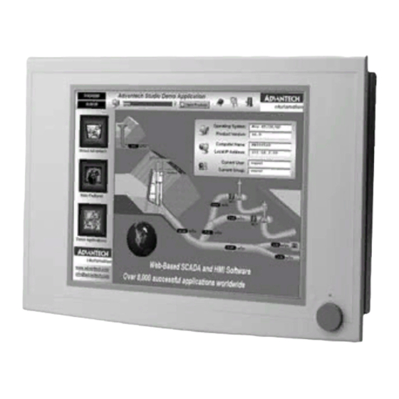
Friendly HMI Systems in the IPPC-6172A series are equipped with a 17" LCD screen, which provides high resolution display quality. The result is vivid, bright, and sharp quality images. The panel PC is perfectly suited for Windows OS. -
Page 11: Specifications
1.2 Specifications 1.2.1 General Dimensions (W x H x D): Front Panel: 481.92 x 355.87 x 26 mm Control Box: 362 x 285 x 112.2 mm Cut out Dimensions: 457 x 342 mm Weight: 13 kg (28 lb) Power Supply: 180 W Input Voltage: 100 V AC ~ 240 V AC @ 50 ~ 60 Hz, 4-2A Output Voltage: +3.3V, 16.8A, +5 V @ 12A, +12 V @ 10A, -12V, 0.8A Disk Drive Housing: Supports 1 x 2.5"SATA HDD, 1 x slim CD-ROM... -
Page 12: Display
1.2.3 Display Chipset: Intel 915GM chip integrated Intel Extreme Graphics 2 for 2D/3D video accelerator Display memory: 128 MB frame buffer using system memory Display type: Simultaneous support of CRT & flat panel displays (TFT) Display resolution: LCD displays up to 1280 x 1024 @ 16.7M colors 1.2.4 Audio Functions Chipset: Integrated in Intel 9151GM ICH6M South Bridge Audio controller:... - Page 13 1.2.7 Environmental Operating Temperature: 0 ~ 50° C (32 ~ 122° F) Storage Temperature: -20 ~ 60° C (-4 ~ 140° F) Relative Humidity: 10 ~ 90% @ 40° C (non-condensing) Shock: 30 G peak acceleration (11 ms duration) Power MTBF: 100,000 hrs Certifications: CE, CCC, FCC Class A, UL, BSMI Chapter 1...
-
Page 14: Dimensions
1.3 Dimensions IPPC-6172A User Manual... - Page 15 System Setup Sections include: • General • Installing SDRAM • Installing a CPU • Installing a 2.5" HDD • Installing Add-on Cards • Mounting Instructions...
-
Page 16: Chapter 2 System Setup
Chapter 2 System Setup 2.1 General Before you start the computer, please follow these procedures for set up: Check and adjust jumpers on the motherboard (see Chapter 3) Install DDR2 SDRAM Install a CPU Install add-on cards Connect the wires, cables and accessories Mount the computer Program the BIOS settings Install an operating system. -
Page 17: Parallel Port
2.1.2 Parallel Port IPPC’s support the latest EPP and ECP parallel port protocols for improved performance with compatible printers or other devices. To connect the panel PC to a printer or other devices: Make sure both the panel PC and the printer/devices are turned off. Connect the 25-pin male connector of the printer cable to the 25- pin female port on the panel PC labelled "parallel port."... -
Page 18: Usb Ports
2.1.5 USB ports An external USB device may be connected to the system via the 4-pin USB ports located on the rear side of the system unit. Connect the external device to the system. The USB ports support hot plug-in connection. You should install the device driver before you use the device. -
Page 19: Installing Sdram
2.2 Installing SDRAM You can install from 128 MB to 2 GB (x2) of DDR2 SDRAM memory. The Panel PC system provides two DDR2 SDRAM sockets Unlock the back cover and open it. Push the two white eject levers on each side of the DIMM outward until they are separated from the black vertical posts. - Page 20 2.3 Installing a CPU The CPU can be upgraded to improve system performance. The system provides Socket 478 architecture which supports Pentium M CPU up to 2.0 GHz, and Celeron M up to 1.5 GHz.. Unlock the back cover and open it(Same as RAM installation). The CPU jumper setting please check Chapter 3 Remove the CPU cooler, then upwards at an angle of 90 degrees.
- Page 21 2.4 Installing a 2.5" SATA HDD You can attach one enhanced Serial Advanced Technology Attachment (SATA) hard disk drive to IPPC6152A’s internal controller which uses PCI local bus interface. The following instructions are for installation: Unscrew the back cover and open it. Remove the two screws and take off CD-ROM, HDD cover.
-
Page 22: Panel Mounting
2.5 Installing Add-on Cards This system supports two PCI expansion cards. Detach the five screws on the back to open the lid. Take away the slot bracket. Insert the add-on card, and put on the lid. 2.6 Mounting Instructions There are two ways to mount the system: panel mounting or rack mounting. 2.6.1 Panel Mounting Take the four mounting brackets out of the accessory box. - Page 23 Jumper Settings & Connectors Sections include: • Jumpers Settings...
-
Page 24: Chapter 3 Jumper Settings &Connectors
Chapter 3 Jumper Settings &Connectors 3.1 Jumper Settings This section tells how to set the jumpers to configure your card. For the locations of each jumper, see the board layout diagram depicted earlier in this chapter. You configure your card to match the needs of your applica- tion by setting jumpers. - Page 25 3.1.1 Jumpers & Switches The motherboard of the IPPC-6172A has a number of jumpers that allow you to configure your system to suit your applications. The table below lists the function of each of the board.s jumpers. LCD Power Select Select LCDPower 3.3V/5V Select CPU VCCA Select CPU VCCA Power 1.5V/1.8V...
- Page 26 3.1.2 Connectors Onboard connectors link the panel PC to external devices such as hard disk drives or floppy drives. The table below lists the function of each of the board.s connectors. CN1, CN2 LVDS 18/24/36/48 BIT LVDS CN3, Wafer 2.54mm 3P 180D(M) CN4,CN5 CONNECTOR FAN CONNECTOR...
-
Page 27: Lcd Power Select(Jp1)
3.1.3 LCD Power Select(JP1) This jumper is used to select LCD Power is +3.3V or +5V LCD Power Select JP1 +3.3V Chapter 3... -
Page 28: Cpu Vcca Power Select (Jp2)
3.1.4 CPU VCCA Power Select (JP2) This jumper is used to select VCCA Power is +1.5V or +1.8V CPU VCCA POWER Selec JP2 +1.5V +1.8V 3.1.5 Measure Battery Current Jumper (JP3) This jumper is used measure batter curren Normal Used series connection to Measure Current Current Meter measure 3.1.6 Clear CMOS (JP4) -
Page 29: Lvds Mode Select(Jp5)
3.1.7 LVDS Mode Select(JP5) 1024 * 768 (24bit) 800 * 600 (18bit) 1280 * 1024 (48bit) 3.1.8 Touchscreen Mode Select (JP6) 5 wire 4 or 8 wire Chapter 3... -
Page 30: Cpu Setting (Cn20 And Jp2)
3.1.9 CPU Setting (CN20 and JP2) CN20 : CPU Setting JP2 : CPU VCCA Setting Dothan Banias Banias 533Mhz 400MHz IPPC-6172A User Manual... - Page 31 Intel Chipset Sections include: • Overview • Utilities and Drivers • Dual Display Setting • Touchscreen Installation & Configuration...
-
Page 32: Chapter 4 Software Configuration
Chapter 4 Software Configuration 4.1 Overview In IPPC-6172A , Advantech provides a CD-ROM with utilities and driv- ers included. Please install the Chipset INF driver, VGA graphics driver, LAN driver, audio driver, Touch Screen driver , Watchdog Timer (WDT) driver sequentially. -
Page 33: Audio Driver
Audio Driver Path: \ audio\ Available for the OS’s below, • Microsoft Windows 2000 • Microsoft Windows XP Touchscreen Driver Path: \ Touch screen \DMC 6000 (Combo) Available for the OS’s below, • Microsoft Windows 2000 • Microsoft Windows XP and more, on the driver CD-ROM. WatchDog Timer Driver Path: \WDT\ Available for the OS’s below:... -
Page 34: Installing The Ippc-6172A Watchdog Timer Driver
4.2.1 Installing the IPPC-6172A Watchdog Timer Driver Insert the companion CD-ROM into your CD-ROM drive. Open Path:\WDT Use Windows Explorer (or Windows Run command) to execute SETUP.EXE from the companion CD-ROM. IPPC-6172A User Manual... - Page 35 Click Next to proceed. Click Next to confirm the customer information. Chapter 4...
- Page 36 Select Advantech [W83627HF] Watchdog Timer and click Next. Click Next to confirm selecting the Typical setup type. IPPC-6172A User Manual...
- Page 37 Click Next to proceed. Click Finish to complete the procedure. Chapter 4...
- Page 38 Click OK to restart the system and activate the Watchdog Timer. IPPC-6172A User Manual...
-
Page 39: How To Use The Ippc-6172A Watchdog Timer
4.2.2 How to Use the IPPC-6172A Watchdog Timer Open the Control Panel and click Watchdog Service Configuration. Click the Start Service button. Click Setting to select the setting page. Chapter 4... - Page 40 Select the Timer Span that meets your application requirement. Click Enable to enable the setting. IPPC-6172A User Manual...
-
Page 41: Dual Display Setting
Click OK, then the configuration procedure is finished. Note Use advantech WDT Driver.WDT was enable,and WDT LED was 1Hz glisten. 4.2.3 Dual Display Setting If you use CRT monitor, you must Connections to CRT port in during system boot up. -
Page 42: Driver Installation
Select Graphics properties This control allows selection of a device page. The currentlyactive is indicated by a checkmark on the icon. If you have multiplede- vices, activation of an alternate device is accomplished by selec- tingthat device icon. Then, select either Apply or OK button. Intel Dual Display Clone is for CRT monitor and IPPC-6172A LCD as the below. - Page 43 Award BIOS Setup Sections include: • Introduction • Entering Setup...
-
Page 44: Chapter 5 Award Bios Setup
Chapter 5 Award BIOS Setup 5.1 Introduction Once you enter the Award BIOS CMOS Setup Utility, the Main Menu (Figure 5-1) will appear on the screen. The Main Menu allows you to select between nine setup functions and two exit choices. Use the arrow keys to select among the items and press <Enter>... -
Page 45: Entering Setup
5.2 Entering Setup Turn on the computer and press <Del> to enter the BIOS setup.. 5.2.1 Standard CMOS Setup Date The date format is <week>, <month>, <day>, <year>. Time The time format is <hour> <minute> <second>, based on 24-hour clock. IDE Primary Master/ Secondary Master/ Secondary Slave •... -
Page 46: Advanced Bios Features Setup
Halt On This category determines whether system start-up will halt or not whenan error is detected during power up. The options are: No Errors/All Errors/All, But Keyboard/All, But Dis- kette/All, But Disk/Key Memory This category displays base memory, extended memory, and total mem- ory detected during POST (Power On Self Test). -
Page 47: Virus Warning
Hard Disk Boot Priority Set hard disk boot device priority. CPU Thermal Monitor The Intel Thermal MonitorAutomatic Mode. There are two Automatic modes called Intel Thermal Monitor 1 (TM1) and Intel Thermal Monitor 2 (TM2). And IPPC-9070 Auto dete C-M or P-M.When CPU was C-M BIOS running in TM1,another running TM2. - Page 48 CPU L1 & L2 Cache Enabled (default) Enable cache Disabled Disable cache Note: The internal cache is built into the processor. Quick Power On Self Test This category speeds up Power On Self Test (POST) after you power on the computer. If this is set to Enabled, BIOS will shorten or skip some check items during POST.
-
Page 49: Security Option
Typematic Rate Setting Keystrokes repeat at a rate determined by the keyboard controller. When enabled, the typematic rate and typematic delay can be selected. The set- tings are: Enabled/Disabled. The default setting is Disabled. Typematic Rate (Chars/Sec) Set the number of times a second to repeat a keystroke key down. The set- tings are: 6, 8, 10, 12, 15, 20, 24, 30. -
Page 50: Advanced Chipset Features Setup
5.2.3 Advanced Chipset Features Setup The Advanced Chipset Features Setup option is used to change the values of the chipset registers. These registers control most of the system options in the computer. Choose the "Advanced Chipset Features" from the main menu and the following screen will appear. - Page 51 DRAM RAS# Precharge If an insufficient number of cycles is allowed for the RAS to accumulate its charge before DRAM refresh, the refresh may be incomplete and the DRAM may fail to retain data. Fast gives faster performance; and Slow gives more stable performance.
-
Page 52: Integrated Peripherals
PCI-E Compliancy Mode This allows the user to select the PCI-E compliant mode. The options are [v1.0], and [v1.0a]. On-Chip Video Memory Size This field let you select On-Chip buffer size. The settings are: 1 and 8. DVMT Mode We have three options (Fixed, DVMT and Both). The default is DVMT. DVMT/FIXED Memory Size We have 64Mb and 128MB. - Page 53 IDE HDD Block Mode Block mode is also called block transfer, multiple commands, or multiple sector read/write. If your IDE hard drive supports block mode (most new drives do), select Enabled for automatic detection of the optimal number of block read/writes per sector the drive can support. The settings are: Enabled (Default), Disabled.
- Page 54 IDE Primary/Secondary Master/Slave UDMA Ultra DMA/33 implementation is possible only if your IDE hard drive supports it and the operating environment includes a DMA driver (Win- dows 95 OSR2 or a third-party IDE bus master driver). If your hard drive and your system software both support Ultra DMA/33 and Ultra DMA/66 and Ultra DMA/100, select Auto to enable BIOS support.
- Page 55 AC97 Audio Select “Disable” if you do not want to use AC-97 audio. Options are “Auto”, and “Disabled”. Onboard Serial Port 1 The settings are “3F8/IRQ4”, “2F8/IRQ3”, “3E8/IRQ4”, “2E8/IRQ3”, and “Disabled” for the on-board serial connector. Onboard Serial Port 2 The settings are “3F8/IRQ4”, “2F8/IRQ3”, “3E8/IRQ4”, “2E8/IRQ3”, and “Disabled”...
-
Page 56: Power Mangement Setup
Parallel Port Mode This field allows you to set the operation mode of the parallel port. The setting "SPP" allows standard speed operation. “EPP” allows bidirec- tional parallel port operation at maximum speed. “ECP” allows the paral- lel port to operate in bidirectional mode and at a speed faster than the maximum data transfer rate. - Page 57 Power Management This category allows you to select the type (or degree) of power saving and is directly related to the following modes: 1. HDD Power Down 2. Suspend Mode There are four selections for Power Management, three of which have- fixed mode settings.
- Page 58 Suspend Mode Please refer to 3.7.3 HDD Power Down You can choose to turn the HDD off after one of the time intervals listed, or when the system is in Suspend Mode. If the HDD is in a power saving mode, any access to it will wake it up.
-
Page 59: Pnp/Pci Configuration Setup
PCI PIRQ [A-D]# When Enabled, the system will resume from suspend mode if interrupt occurs. The choice: Enabled, Disabled. 5.2.6 PNP/PCI Configuration Setup This section describes configuring the PCI bus system. PCI, or Personal Computer Interconnect, is a system that allows I/O devices to operate at speeds nearing the speed the CPU itself uses when communicating with its own special components. - Page 60 Resource Controlled By The Award Plug and Play BIOS has the capacity to automatically config- ure all the boot and Plug and Play compatible devices. However, this capability means absolutely nothing unless you are using a Plug and Play operating system such as Windows® 95/98. If you set this field to "man- ual,"...
-
Page 61: Pc Health Status
5.2.7 PC Health Status This section shows the Status of you CPU, System Temp, Warning for overall system status. This is only available if there is Hardware Monitor onboard. CPU Warning Temperature This item will prevent the CPU from overheating. The choices are “Dis- abled”, “50C/122F”, “53C/127F”, “56C/133F”, “60C/140F”, “63C/ 145F”, “66C/151F”, “70C/158F”, “75C/167F”, “80C/176F”, “85C/ 185F”, “90C/194F”, and “95C/205F”. -
Page 62: Spread Spectrum Control
5.2.8 Spread Spectrum Control Spread Spectrum This item allows you to enable spread spectrum function. Default is "Dis- abled." 5.2.9 Load Optimized Defaults When you press <Enter> on this item, you get a confirmation dialog box with a message similar to: Load Optimized Defaults (Y/N) ? N Pressing 'Y' loads the default values that are factory settings for optimal perfor- mance system operations. -
Page 63: Set Password
5.2.10 Set Password To change, confirm, or disable the password, choose the "PASSWORD SETTING" option form the Setup main menu and press [Enter]. The password can be at most 8 characters long. Remember, to enable this fea- ture. You must first select the Security Option in the Advanced BIOS Features Setup to be either "Setup"... -
Page 64: Save & Exit Setup
5.2.11 Save & Exit Setup If you select this and press the [Enter] key, the values entered in the setup utilities will be recorded in the CMOS memory of the chipset. The micro- processor will check this every time you turn your system on and com- pare this to what it finds as it checks the system. - Page 65 IO & Connector Pin Assignments...
-
Page 66: Appendix A Io & Connector Pin Assigns
Appendix A IO & Connector Pin Assigns A.1 CN1,CN2 LVDS VDDSAFE VDDSAFE LCD_A_D3P LCD_A_D3N LCD_A_CLKP LCD_A_CLKN LCD_A_D2P LCD_A_D2N LCD_A_D1P LCD_A_D1N LCD_A_D0P LCD_A_D0N LCD_DCLK LCD_DDAT DF19G_20V_S1.00mm VDDSAFE VDDSAFE LCD_B_CLKP LCD_B_CLKN LCD_B_D3P LCD_B_D3N LCD_B_D2P LCD_B_D2N LCD_B_D1P LCD_B_D1N LCD_B_D0P LCD_B_D0N DF19G_20V_S1.00mm IPPC-6172A User Manual... -
Page 67: Cn9 Lcd Inverter
A.2 CN9 LCD INVERTER W_7H_2.00mm 30_100MHz LCDBLPWRVCC LCD_VBR LCD_BACKON# LCDBLPWR +12V 30_100MHz A.3 CN12 Touchscreen CN30 TP_Y - TP_Y + TP_X- TAVSS TP_X+ TP_SENSE WB_9V_2.0mm Chapter A... -
Page 68: Cn15/Cn17 Usb 6,7
A.4 CN15/CN17 USB 6,7 CN14 USBD6+ USBD6- USBV67 W_5V_2.54mm A.5 CN19,CN21 SATA POWER +12V SATA2_VCC12 30_100MHz SATA2_VCC5 30_100MHz VCC3 SATA2_VCC3 30_100MHz N197 N198 N199 WB_8V_2.54mm 0.1uF 0.1uF 0.1uF IPPC-6172A User Manual... -
Page 69: Cn10 Ide
A.6 CN10 IDE SLIM TYP E CD-ROM C N17 C D_L_R C D_R_R C D_REF C D_REF ID ERST#1 ID E_PD D8 ID E_PD D7 ID E_PD D9 ID E_PD D6 ID E_PD D10 ID E_PD D5 ID E_PD D11 ID E_PD D4 ID E_PD D12 ID E_PD D3... - Page 70 A.8 CN34 : DB-15 VGA Connector Definitions Signal GREEN BLUE (VGAVCC) N/ C VGA_SDA HSYNC VSYNC VGA_SCL IPPC-6172A User Manual...
-
Page 71: Cn30 : Ps/2 K/B & Mouse Connector Definitions
A.9 CN30 : PS/2 K/b & Mouse Connector Definitions Signal KB DATA KB CLOCK MS DATA MS CLOCK A.10 CN28,CN29 : USB 0,1,2,3 Connector Definitions Chapter A... - Page 72 A.11 10/100/1000Base-TX Ethernet 10/100Base-TX 10/100/1000Base-TX Signal Signal MDIAX1+ MDIAX1- MDIAX2+ MDIAX3+ MDIAX3- MDIAX2- MDIAX4+ MDIAX4- LED Indicator Definition L eft R ight 10M bps O ff flick active/link m ode 100M bps G reen 1000M bps O range USB Ports Pin Definitions Signal USB_P- USB_P+...
- Page 73 Secondary IDE Connector for 2.5" HDD Pin Definitions Signal Signal IDERST* SDD7 SDD8 SDD6 SDD9 SDD5 SDD10 SDD4 SDD11 SDD3 SDD12 SDD2 SDD13 SDD1 SDD14 SDD0 SDD15 SDDREQ SDIOW* SDIOR* SDIORDY SDDACK* IRQ15 SDA1 S66DET SDA0 SDA2 SDCS*1 SDCS*3 HDD_LED *Low Active Chapter A...
- Page 74 CN36 : Serial port 1,2 RS232 Connector Definitions Signal NDCD NDTR NDSR NRTS NCTS 2F-SA0 : Serial ATA0 (7pin connector) Signal IPPC-6172A User Manual...
- Page 75 System Assignments...
-
Page 76: Appendix B System Assignments
Appendix B System Assignments B.1 System I/O Ports Addr. Range (Hex) Device 000-01F DMA controller 020-021 Interrupt controller 1, master 022-023 Chipset address 040-05F 8254 timer 060-06F 8042 (keyboard controller) 070-07F Real-time clock, non-maskable interrupt (NMI) mask 080-09F DMA page register 0A0-0BF Interrupt controller 2 0C0-0DF... -
Page 77: Dma Channel Assignments
B.2 DMA Channel Assignments Channel Function Available Available Available Available Cascade for DMA controller 1 Available Available Available B.3 Interrupt Assignments Priority Interrupt# Interrupt Source Parity error detected IRQ0 Interval timer IRQ1 Keyboard - IRQ2 Interrupt from controller 2 (cascade) IRQ8 Real-time clock IRQ9... -
Page 78: 1St Mb Memory Map
B.4 1st MB Memory Map Addr. range (Hex) Device E0000h - FFFFFh System ROM CC000h - DFFFFh Unused C0000h - CBFFFh VGA BIOS A0000h - BFFFFh VGA buffer 00000h - 9FFFFh Base memory B.5 PCI Bus Map Function Signals: Device ID INT# Pin GNT# Pin Onboard LAN1... - Page 79 Watchdog Timer...
-
Page 80: Appendix C Watchdog Timer
Appendix C Watchdog Timer C.1 Overview The IPPC-9070 cards’ watchdog timer can be used to monitor system software operation and take corrective action if the software fails to func- tion after the programmed period. This section describes the operation of the watchdog timer, and how to program it. - Page 81 Appendix C...
- Page 82 Register Attribute Description Address (2E) Read/Write Value (2F) and description 87 (hex) ----- Write this address to I/O address port 2E (hex) twice to unlock the W83627HF 07 (hex) write Write 08 (hex) to select register of watchdog timer. 30 (hex) write Write 01 (hex) to enable the function of the watchdog timer.
-
Page 83: Example Programs
C.3 Example Programs 1. Enable watchdog timer and set 10 sec. as timeout interval ;----------------------------------------------------------- Mov dx,2eh ; Unlock W83627HF Mov al,87h Out dx,al Out dx,al ;----------------------------------------------------------- Mov al,07h ; Select registers of watchdog timer Out dx,al Inc dx Mov al,08h Out dx,al ;----------------------------------------------------------- Dec dx ;... - Page 84 Mov al,0aah Out dx,al 2. Enable watchdog timer and set 5 minutes as timeout interval ;----------------------------------------------------------- Mov dx,2eh ; unlock W83627H Mov al,87h Out dx,al Out dx,al ;----------------------------------------------------------- Mov al,07h ; Select registers of watchdog timer Out dx,al Inc dx Mov al,08h Out dx,al ;-----------------------------------------------------------...
- Page 85 Dec dx ; lock W83627HF Mov al,0aah Out dx,al 3. Enable watchdog timer to be reset by mouse ;----------------------------------------------------------- Mov dx,2eh ; unlock W83627H Mov al,87h Out dx,al Out dx,al ;----------------------------------------------------------- Mov al,07h ; Select registers of watchdog timer Out dx,al Inc dx Mov al,08h Out dx,al...
- Page 86 Mov al,87h Out dx,al Out dx,al ;----------------------------------------------------------- Mov al,07h ; Select registers of watchdog timer Out dx,al Inc dx Mov al,08h Out dx,al ;----------------------------------------------------------- Dec dx ; Enable the function of watchdog timer Mov al,30h Out dx,al Inc dx Mov al,01h Out dx,al ;----------------------------------------------------------- Dec dx ;...
- Page 87 Mov al,08h Out dx,al ;----------------------------------------------------------- Dec dx ; Enable the function of watchdog timer Mov al,30h Out dx,al Inc dx Mov al,01h Out dx,al ;----------------------------------------------------------- Dec dx ; Generate a time-out signal Mov al,0f7h Out dx,al ;Write 1 to bit 5 of F7 register Inc dx In al,dx Or al,20h...
- Page 88 IPPC-6172A User Manual...
Need help?
Do you have a question about the IPPC-6172A Series and is the answer not in the manual?
Questions and answers