
Related Manuals for Advantech IPPC-4001 Series


Summary of Contents for Advantech IPPC-4001 Series
-
Page 1: Users Manual
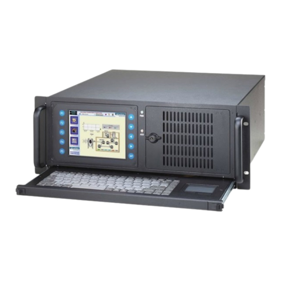
IPPC-4001 Series 5.7" VGA TFT LCD 4U 19" Rack Industrial Panel PC with 14 Expansion Slots & Keyboard Drawer Users Manual... - Page 2 Copyright This document is copyrighted, 2009, by Advantech Co., Ltd. All rights are reserved. Advantech Co., Ltd. reserves the right to make improve- ments to the products described in this manual at any time without notice. No part of this manual may be reproduced, copied, translated or transmit- ted in any form or by any means without the prior written permission of Advantech Co., Ltd.
- Page 3 Additional Information and Assistance Step 1. Visit the Advantech web site at www.advantech.com where you can find the latest information about the product. Step 2. Contact your distributor, sales representative, or Advantech's cus- tomer service center for technical support if you need additional assistance.
-
Page 4: Safety Instructions
The sound pressure level at the operator's position according to IEC 704-1:1982 is no more than 70 dB (A). DISCLAIMER: This set of instructions is given according to IEC 704-1. Advantech disclaims all responsibility for the accuracy of any statements contained herein. -
Page 5: Table Of Contents
Specifications ..............2 1.2.1 General ................2 1.2.2 System Hardware ............3 1.2.4 Environment ..............3 IPPC-4001 Series List ............4 Dimensions................ 4 Exploded Diagram............. 5 Figure 1.1:Exploded Diagram ........5 Accessory Packing list ............5 Chapter 2 System Setup............ 8 System Installation ............ - Page 6 IPPC-4001 User Manual...
- Page 7 General Information Chapter 1...
-
Page 8: Chapter 1 General Information
SBC status, voltages, power supply, cooling fans and temperature through web browser by minimizing system down time. A wide range of standard computing peripherals from current Advantech IPC family can be inte- grated into the IPPC-4001 to meet different application development. -
Page 9: Environment
1.2.2 Passive Backplane • Passive Backplane PCA-6114P10 • Slots 2 PICMG, 10 PCI, 2 ISA • Backplane Size 315 x 260 mm (12.4" x 10.24") • PCI Bridge Pericom PI7C8150MA • PCI Slot Primary 3 slots, Secondary: 7 slots 1.2.3 LCD Display •... -
Page 10: Dimensions
1.3 Dimensions IPPC-4001 User Manual... - Page 11 System Setup Chapter 2...
-
Page 12: Chapter 2 System Setup
Chapter 2 System Setup 2.1 System Installation WARNING: Before starting the installation process, be sure to shut down all power from the chassis. Do this by turning off the power switch, and unplugging the power cord from the power outlet. When in doubt, consult with an experienced technician. - Page 13 System Reset 1: Press this switch to reinitialize the system. This is the same as the hardware reset button. (Default setting) System Reset 2: Press this switch to reinitialize the second system. (Optional) Alarm Reset Switch: Press this switch to suppress or stop an audible alarm.
-
Page 14: Drive Bay Installation
2.1.4 Drive Bay Installation The drive bay of IPPC-4001 can hold 5.25" (x3) devices. Installation of disk drives: Remove the top cover Undo the two screws of cushion and four screws on the drive bay Lift off the Standard Drive Bay. Insert the drives into their proper locations in the drive bay and secure them with the screws provided. -
Page 15: Power Status Led
2.2.2 Power Status LED Power Status LED indicates the status of the backplane voltage signals. When a LED fails to light, it indicates a problem with one of the voltage signals. An audible alarm is sounded. Check to make sure that the power supply connector is properly attached to the backplane. -
Page 16: Cooling Fan & Filter
2.4 Cooling Fan & Filter There are two cooling fans located inside the chassis. When one cooling fan breaks down, the system sounds a continuous alarm. To disable the alarm, press the Alarm Reset switch and replace the fan immediately. To replace a defective fan, refer to the figures below. - Page 17 Alarm Board Chapter 3...
-
Page 18: Chapter 3 Alarm Board
Chapter 3 Alarm Board The alarm board is located under the cooling fan section. It gives an audible alarm when: Any power supply module of redundant power supply fails One of the cooling fans fai1s Temperature inside the chassis rises A problem occurs in one of the backplane voltage levels The detailed layout and specification of the alarm board are as follows: 3.1 Alarm Board Layout... -
Page 19: Alarm Board Specification
3.2 Alarm Board Specification Input Power: +5V , +12V Input Signals: • 7 FAN connectors (GND_+12V_FAN) • One thermal board connector (up to 8 thermal boards in a roll) • One power good input • One alarm reset input. • One voltage signal connector (connect from backplane, includes ±12V , ±5V , 3.3V) •... - Page 20 Pin Definition CN1 : External Power Connector, standard mini 4 Pin power connector Pin 1 : +12V, 2A current maximum Pin 2 : GND Pin 3 : GND Pin 4 : +5V, 2A current maximum CN2 : 10/100M LAN Connector Pin 1 : SPLED Pin 2 : TERMPLANE Pin 3 : RX+...
- Page 21 CN11 : SNMP-1000 Daughter Board Connector (Left side) Pin 1 : SIN Pin 2 : SOUT Pin 3 : CTS# Pin 4 : DCD# Pin 5 : RTS# Pin 6 : DTR# Pin 7 : DSR# Pin 8 : ID 0 Pin 9 : ATX ON Pin 10 : DO 4 Pin 11 : GND...
- Page 22 CN13 : Voltage Detect Input Connector Pin 1 : 5VSB Pin 2 : GND Pin 3 : GND Pin 4 : -5V Pin 5 : +5V Pin 6 : +3.3V Pin 7 : -12V Pin 8 : +12V CN16 : 4 bit Power Good Input, Pin 1 : Power GOOD A Pin 2 : GND CN18 : LED Board Connector...
-
Page 23: Switch Setting
3.3 Switch Setting Fan Number Setting Thermal Board Temperature Setting Chapter 3... - Page 24 IPPC-4001 User Manual...
Need help?
Do you have a question about the IPPC-4001 Series and is the answer not in the manual?
Questions and answers