Table of Contents
Advertisement
Quick Links
Download this manual
See also:
Instruction Manual
Advertisement
Table of Contents

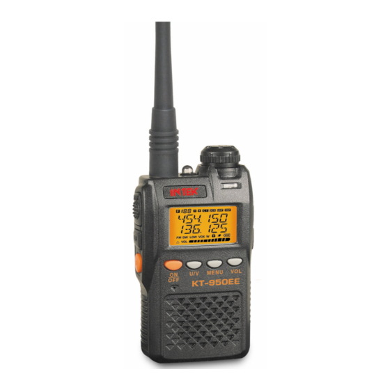
Summary of Contents for Intek KT-950EE
- Page 1 Ser vice Manual INTEK Model:KT-950EE www.intek-radios.com...
-
Page 2: Table Of Contents
------------------ -------------------- CONTENTS INTRODUCTION ELECTRICAL FEATURES FEATURE LCD DISPLAY KEY FUNCTION CIRCUIT DESCRIPTION BLOCK DIAGRAM CIRCUIT DIAGRAM PARTS LAYOUT PART LIST www.intek-radios.com... -
Page 3: Introduction
▣ In order to avoid the problem arising by Electromagnetic interference and/or ▣ Electromagnetic Compatibility, please turn off the radio where there has a ▣ mark: Turn off radio, such as hospital or other health care place and enplane. www.intek-radios.com... -
Page 4: Electrical Features
Electrical Features 1-1 STANDARD TEST CONDITIONS Supply 3 7 . V DC Voltage ● Antenna Impedance 50 Ohm ● Audio Frequency 1 KHz ● Main Signal Input ‐47 dBm ● Deviation 3Khz / N : 1.5KHz ● 1 5 . Vrms at external Speaker Reference Audio Output Power ●... -
Page 5: Feature
Priority Scan Function ● Switching Between Channel Mode /VFO Mode ● Display Channel + Frequency Mode ● Adjust Squelch Level(0-9) ● Busy Channel Lockout ● Keypad Lock ● Scan Channel Delete ● Low Battery Alert ● Battery Saver ● Time-out Timer -www.intek-radios.com... -
Page 6: Lcd Display
www.intek-radios.com... -
Page 7: Key Function
Long press for the radio function. F MODE ] : : Scanning function. F V M +[ / ]: : All frequency mode memory function. F DIAL +‐ 1Mhz MON VOL DIAL : Adjust the volume. www.intek-radios.com... -
Page 8: Circuit Description
Circuit Description The KT-950EE contains power control circuit,RF transceiver integrated IC, RF receiver amplifier circuit, RF transceiver amplifier circuit, audio power amplifier circuit, FM radio integrated IC, microprocessor and LCD display. A. power control circuit 1.With 3.7 V working voltage and 1200 mAH lithium battery. - Page 9 27 Pin 28 Pin Q26 Q11 Q12 constitute a separate V U band transceiver power 、 and receiver power Q9 Q11 control VHF VRX VHF VTX power when 30 pin of the chip RF001 is in high potential both of Q9 Q11 will make the conduction;And Q26 Q12 control UHF VRX...
- Page 10 B. RF transceiver integrated IC www.intek-radios.com RF transceiver integrated IC is a half-duplex FM radio transceiver,it can work in 136 ~ 174 MHZ, 400 ~ 470 MHZ. The transceiver integrates the high performance PLL,ADC/DAC,and with the advanced digital signal processing ability. This IC integrates all the radio’s RF transceiver channel circuit,which only require very little peripheral devices to complete RF transceiver function.
- Page 11 D. RF transceiver amplifier circuit www.intek-radios.com 1. 136 ~ 174 MHZ band transceiver The Voice signal via MIC1 comes into the RF transceiver integrated IC through the analog numerical transformation, digital filter ,amplification, direct modulation,and get the 136-174Mhz RF frequency modulation signal from the output terminal of the RF transceiver integrated IC.
- Page 12 E.audio power amplifier circuit www.intek-radios.com Rf transceiver integrated IC will receive the RF FM through it’s internal low- noise amplifier, direct down-conversion to low and intermediate frequency through the amplifier and analog-digital converter into a digital signal by the digital signal processor for digital FM demodulation. Demodulated audio baseband signal through the audio output amplifier U5 to the speaker.
- Page 13 、 F FM radio integrated IC www.intek-radios.com FM radio signal comes into antenna, amplifies by high-frequency amplifier Q13 input to FM radio IC, then demodulate and output the audio signal through voice amplifier output to the speaker. -13-...
- Page 14 、 F microprocessor and LCD display www.intek-radios.com With 8 bit microprocessor U1 programming, control the whole transceiver circuit and other function modules,LCD displays related information by it’s drive . -14-...
-
Page 17: Parts Layout
6.Parts Layout www.intek-radios.com Side A ... - Page 18 ...
- Page 19 www.intek-radios.com Side B ...
- Page 20 ...
-
Page 21: Part List
7、Parts List www.intek-radios.com Laminated Laminated Laminated Laminated Wire Wound Laminated... - Page 22 Warm up (Green) (Red) Dome sheet (Main Board) (KeyPad Board)


Need help?
Do you have a question about the KT-950EE and is the answer not in the manual?
Questions and answers