
Related Manuals for Horizon Hobby Blade 450X


Summary of Contents for Horizon Hobby Blade 450X
- Page 1 ® Instruction Manual Bedienungsanleitung Manuel d’utilisation Manuale di Istruzioni...
- Page 2 NOTICE All instructions, warranties and other collateral documents are subject to change at the sole discretion of Horizon Hobby, LLC. For up-to-date product literature, visit horizonhobby.com and click on the support tab for this product. Meaning of Special Language The following terms are used throughout the product literature to indicate various levels of potential harm when operating this product: NOTICE: Procedures, which if not properly followed, create a possibility of physical property damage AND a little or no possibility of injury. CAUTION: Procedures, which if not properly followed, create the probability of physical property damage AND a possibility of serious injury. WARNING: Procedures, which if not properly followed, create the probability of property damage, collateral damage, and serious injury OR create a high probability of superficial injury. WARNING: Read the ENTIRE instruction manual to become familiar with the features of the product before operating. Failure to operate the product correctly can result in damage to the product, personal property and cause serious injury. This is a sophisticated hobby product. It must be operated with caution and common sense and requires some basic mechanical ability. Failure to operate this Product in a safe and responsible manner could result in injury or damage to the product or other property. This product is not intended for use by children without direct adult supervision. Do not use with incompatible components or alter this product in any way outside of the instructions provided by Horizon Hobby, LLC. This manual contains instructions for safety, operation and maintenance. It is essential to read and follow all the instructions and warnings in the manual, prior to assembly, setup or use, in order to operate correctly and avoid damage or serious injury. Age Recommendation: Not for children under 14 years. This is not a toy. Safety Precautions and Warnings • Always keep a safe distance in all directions around your model to avoid colli- • Never operate your model with low transmitter batteries. sions or injury. This model is controlled by a radio signal subject to interference • Always keep aircraft in sight and under control. from many sources outside your control. Interference can cause momentary loss • Always move the throttle fully down at rotor strike.
-
Page 3: Table Of Contents
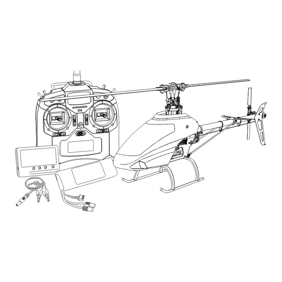
® Box Contents: • Blade 450 X • 3S 11.1V 2200mAh 30C Li-Po Battery • DC Li-Po Balancing Charger • Spektrum DX6i Transmitter • 4 AA Batteries Table of Contents First Flight Preparation ..................4 Gyro Gain Adjustment ..................9 Flying Checklist ....................4 Blade Helicopter Belt Tension ................9 Charging Warnings....................4 Post-Flight Inspections and Maintenance ............. 9 Battery Charging ....................4 AR7200BX Default Blade 450 X Setup ..............10 Low Voltage Cutoff (LVC) .................. -
Page 4: First Flight Preparation
First Flight Preparation Flying Checklist • Remove and inspect contents ❏ Always turn the transmitter on first • Begin charging the flight battery ❏ Plug the flight battery into the lead from the ESC • Install the flight battery in the helicopter (once it has been fully charged) ❏ Allow the ESC to initialize and arm properly • Program your computer transmitter ❏ Fly the model • Bind your transmitter (BNF only) ❏ Land the model • Familiarize yourself with the controls ❏ Unplug the flight battery from the ESC • Find a suitable area for flying ❏ Always turn the transmitter off last Charging Warnings The Battery Charger (EFLC3115) included with your helicopter has been designed • Always charge batteries away from flammable materials. to safely charge the Li-Po battery. • Always inspect the battery before charging. • Always disconnect the battery after charging, and let the charger cool between CAUTION: All instructions and warnings must be followed exactly. -
Page 5: Low Voltage Cutoff (Lvc)
Low Voltage Cutoff (LVC) The ESC will continuously lower power to the motor until complete shutdown Repeatedly flying the helicopter until LVC activates will damage the helicopter when the battery reaches 9V under load. This helps prevent over-discharge of the battery. Li-Po battery. Land immediately when the ESC activates LVC. Continuing to fly after Disconnect and remove the Li-Po battery from the aircraft after use to prevent LVC can damage the battery, cause a crash or both. Crash damage and batteries trickle discharge. During storage, make sure battery charge does not fall below 3V damaged due to over-discharge are not covered under warranty. per cell. Installing the Transmitter Batteries Replace transmitter batteries when the transmitter beeps and flashes a warning screen. Transmitter Functions Function Function Function Function Aileron/Elevator Stick (Mode 2) Gear/Flight Mode (Mode 2) A Antenna K Charge Port Aileron/Throttle Stick (Mode 1) Rudder Dual Rate (Mode 1) L Rudder Trim B Throttle Cut Elevator Trim (Mode 2) Trainer/Bind (Mode 2) Throttle Trim (Mode 1) Mix/Throttle Hold (Mode 1) Throttle Trim (Mode 2) -
Page 6: Transmitter Setup
Mechanical Conversion Mechanical conversion is required to change between Modes 1 and 2. The the throttle gimbal. Tighten the opposite throttle strap to engage the desired mechanical conversion consists of the following steps: throttle ratchet. Removing the Rear Case: Adjusting the Elevator Centering Screw: 1. Power off the transmitter and remove the transmitter batteries. When changing between Modes 1 and 2, you must adjust the elevator centering screw. 2. Remove the six Phillips head screws that secure the rear transmitter case half. 1. Hold the Elevator or Throttle stick in the full up or full down position when you 3. Put the transmitter face down on a piece of foam or a towel and remove the are adjusting the elevator centering screw. Holding the gimbal stick reduces rear case. the load on the elevator centering mechanism and makes it easier to adjust CAUTION: Use care to not pull or disconnect any of the wires attached to the centering screw. the back transmitter half. 2. Locate the gimbal where the elevator centering spring is engaged. Use a Phillips screwdriver to tighten the elevator centering screw. Tightening the Changing the Throttle Ratchet: screw will disengage the centering spring. 1. Locate the silver throttle friction straps on both gimbals. 3. Using a Phillips screwdriver, loosen the opposite elevator centering screw until 2. To change the throttle ratchet, loosen the throttle strap so it does not touch the lever engages. -
Page 7: Transmitter And Receiver Binding
Transmitter and Receiver Binding The transmitter comes prebound to the model. If you need to rebind, follow the directions below. Binding Procedure 1. Insert the bind plug in the BND/DAT port on the receiver. 2. Connect the flight battery to the ESC. The H menu LED should be flashing, indicating the AR7200BX is in bind mode. 3. Move the throttle stick to the desired failsafe position (low throttle position in normal mode). 4. Power on the transmitter while holding the Trainer/Bind switch. Hold the Trainer/Bind switch until binding is complete. The system will connect within a few seconds. Once connected, the H LED will turn off and the AR7200BX will start the initialization process. 5. When the initialization process is complete, menu LED H will turn OFF and the Status LED light will come ON solid BLUE. 6. Disconnect the flight battery and remove the bind plug from the AR7200BX. Store the bind plug in a convenient place. WARNING: You must move the throttle to the LOW/OFF position during NOTICE: Remove the bind plug to prevent the system from entering bind mode the binding. Failure to do so may cause the rotor blades to spin and the heli- next time the power is turned on. copter to lift during the AR7200BX initialization, which could result in damage to If you encounter problems, obey binding instructions and refer to transmitter property and injury. troubleshooting guide for other instructions. If needed, contact the appropriate Horizon Product Support office. Throttle Hold Throttle hold only turns off the motor on an electric helicopter. You maintain pitch Throttle hold is also used to turn off the motor if the helicopter is out of control, in and direction control. danger of crashing, or both. The blades will spin if throttle hold is OFF. For safety, turn throttle hold ON any time you need to touch the helicopter or check the direction controls. Control Tests CAUTION: You must complete the Rudder and Cyclic tests prior to flight. Failure to complete the tests ensuring the sensor directions are not reversed can cause the helicopter to crash, resulting in property damage and injury. -
Page 8: Pre-Flight Checklist
Cyclic and Collective Control Test Turn on Throttle Hold when doing the control tests. Elevator Side View Side View Aileron Rear View Rear View Collective Pitch Rear View Rear View Motor WARNING: Stay at least 30 feet (10 meters) away from the helicopter Place the helicopter outdoors on a clean, flat and level surface (concrete or asphalt) free of obstructions. Always stay clear of moving rotor blades. when the motor is running. Do not attempt to fly the helicopter at this time. 1. The motor beeps twice when the helicopter’s ESC arms properly. Before you continue, confirm that TH HOLD is ON. 3. Ensure the throttle is lowered completely. Confirm the transmitter is still set to normal flight mode. Turn throttle hold off at this time. Slowly increase the WARNING: The motor will spin when throttle is increased while TH HOLD throttle until the blades begin to spin. The main blades spin clockwise when is OFF. viewing the helicopter from the top. The tail rotor blades spin counterclockwise 2. Check the swashplate directions to ensure they are moving in the correct when viewing the helicopter from the right-hand side. -
Page 9: Gyro Gain Adjustment
Consult local laws and ordinances before choosing a location First flights should be performed in normal mode and low cyclic and rudder dual to fly your aircraft. rates until you are familiar with the flying manner of the Blade 450 X. Discover the rates that fit your flying style. Select a large, open area away from people and objects. Your first flights should be outdoors in low-wind conditions. Always stay at least 30 feet (10 meters) away CAUTION: Always fly the helicopter with your back to the sun and the from the helicopter when it is flying. wind to prevent loss of flight control. The Blade 450 X is intended to be flown outdoors. Landing CAUTION: The Blade 450 X is intended for pilots with experience Establish a low level hover. Deliberately lower the throttle until the helicopter flying aerobatic, collective pitch helicopters. The Blade 450 X is more lands. Do not give any aileron, elevator or rudder commands when the helicopter responsive than other Blade helicopters. If you are not an experienced 3D or is landing. collective pitch helicopter pilot, do not attempt to fly this product. When the helicopter is in stunt mode: Takeoff • The rotor head speed is constant. • The main rotor will increase negative pitch as the throttle/collective stick is Deliberately increase throttle and establish a hover at least 24” (0.6 meter) high, moved from the middle stick position to the low stick position. Negative pitch... -
Page 10: Ar7200Bx Default Blade 450 X Setup
AR7200BX Default Blade 450 X Setup Firmware version 4503.0.0 SETUP MENU Menu LED solid Status-LED: Purple Red Flashing Red Solid Blue Flashing Blue Solid Mounting orientation upright (vertical) flat (horizontal)* Swashplate servo - frequency User defined 50 Hz 65 Hz 120 Hz 165 Hz 200 Hz* Tail servo - center position pulse length User defined 960 μs 760 μs 1520 μs*... -
Page 11: Ar7200Bx Fine-Tuning And Adjustment
AR7200BX Fine-tuning and Adjustment Observed Behavior Suggested Adjustment Cyclic response too slow or too fast Adjust the control behavior parameter in the AR7200BX to fit your flying style. Control inputs feel delayed Increase Dial 2 on the AR7200BX The helicopter seems to overshoot control input and then return Decrease Dial 2 on the AR7200BX The helicopter tail stops too abruptly Decrease Dial 3 on the AR7200BX Increase Dial 3 on the AR7200BX Increase the rudder gain in your transmitter The helicopter tail does not stop precisely Adjust the rudder heading lock gain parameter in the AR7200BX Make sure the tail drive belt tension is adjusted correctly Troubleshooting Guide Problem Possible Cause Solution Low flight battery or transmitter battery voltage Fully charge or replace the flight battery and/or transmitter batteries AR7200BX is not in bind mode Make sure the bind plug is connected to the AR7200BX BND/DAT port Helicopter will not bind Power on the transmitter while holding the Trainer/Bind switch. Hold the Trainer/Bind switch to the transmitter Transmitter is not in bind mode until binding is complete (during binding) Transmitter too close to the helicopter during binding Power off the transmitter. Move the transmitter to a larger distance from the helicopter. process Disconnect and reconnect the flight battery to the helicopter and follow binding instructions Helicopter is bound to a different model memory Disconnect the flight battery. Select the correct model memory on the transmitter... -
Page 12: Limited Warranty
Product in, please use the Horizon Online Service Request submission of the Product, (iv) attempted service by anyone other than a Horizon Hobby authorized process found on our website or call Horizon to obtain a Return Merchandise service center, (v) Product not purchased from an authorized Horizon dealer, or (vi) Authorization (RMA) number. -
Page 13: Fcc Information
FCC Information This device complies with part 15 of the FCC rules. Operation is subject to the fol- Antenna Separation Distance lowing two conditions: (1) This device may not cause harmful interference, and (2) When operating your Spektrum transmitter, this device must accept any interference received, including interference that may please be sure to maintain a separation distance cause undesired operation. of at least 5 cm between your body (excluding fingers, hands, wrists, ankles and feet) and the CAUTION: Changes or modifications not expressly approved by the party antenna to meet RF exposure safety require- responsible for compliance could void the user’s authority to operate the ments as determined by FCC regulations. equipment. The following illustrations show the approximate This product contains a radio transmitter with wireless technology which has been 5 cm RF exposure area and typical hand place- tested and found to be compliant with the applicable regulations governing a radio ment when operating your Spektrum transmitter. transmitter in the 2.400GHz to 2.4835GHz frequency range. IC Information This device complies with Industry Canada license-exempt RSS standard(s). (1) this device may not cause interference, and (2) this device must accept any inter- Operation is subject to the following two conditions: ference, including interference that may cause undesired operation of the device. Compliance Information for the European Union Declaration of Conformity Instructions for disposal of WEEE by users in the European Union (in accordance with ISO/IEC 17050-1) This product must not be disposed of with other waste. Instead, it is the No. HH2014070201U1...
Need help?
Do you have a question about the Blade 450X and is the answer not in the manual?
Questions and answers