Table of Contents
Advertisement
Quick Links
Created 6/23
614044.1
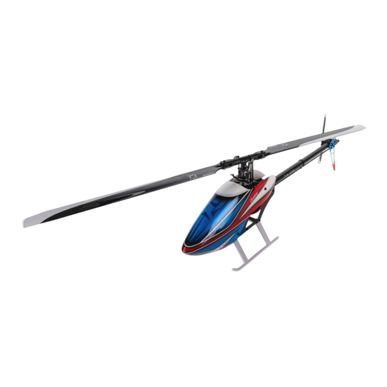
Fusion 550
Scan the QR code and select the Manuals and Support quick links from the
product page for the most up-to-date manual information.
Scannen Sie den QR-Code und wählen Sie auf der Produktseite die Quicklinks
Handbücher und Unterstützung, um die aktuellsten Informationen zu Handbücher.
Scannez le code QR et sélectionnez les liens rapides Manuals and Support sur la
page du produit pour obtenir les informations les plus récentes sur le manuel.
Scannerizzare il codice QR e selezionare i Link veloci Manuali e Supporto dalla
pagina del prodotto per le informazioni manuali più aggiornate.
BLH4975, BLH4975C
Instruction Manual
Bedienungsanleitung
Manuel d'utilisation
Manuale di Istruzioni
Advertisement
Table of Contents

Related Manuals for Horizon Hobby Blade Fusion 550


Summary of Contents for Horizon Hobby Blade Fusion 550
- Page 1 BLH4975, BLH4975C Fusion 550 Instruction Manual Bedienungsanleitung Manuel d’utilisation Manuale di Istruzioni Scan the QR code and select the Manuals and Support quick links from the product page for the most up-to-date manual information. Scannen Sie den QR-Code und wählen Sie auf der Produktseite die Quicklinks Handbücher und Unterstützung, um die aktuellsten Informationen zu Handbücher.
- Page 2 Product in a safe and responsible manner could result in injury or damage to the product or other property. This product is not intended for use by children without direct adult supervision. Do not use with incompatible components or alter this product in any way outside of the instructions provided by Horizon Hobby, LLC. This manual contains instructions for safety, operation and maintenance.
-
Page 3: Table Of Contents
Table of Contents Head Assembly (Bags H, A) ................4 Flight Guidelines and Warnings ..............23 Frame Assembly (Bags A, F, M, T) ..............5 Flying Your Fusion 550 ................23 Tail Assembly (Bags B, M, T) ............... 11 Preflight Checklist ..................23 Flight Controller Mounting Plate .............. -
Page 4: Head Assembly (Bags H, A)
Head Assembly (Bags H, A) Bag H1, H2, H3 1. The main rotor head assembly and swashplate are pre-assembled with thread locking compound. If you disassemble the fasteners, use medium strength thread-locking compound for reassembly. 2. Install the follower arms to the head block with a 2.5mm hex driver using one M3x20mm socket head cap screw and two washers per arm and medium thread-locking compound. -
Page 5: Frame Assembly (Bags A, F, M, T)
Bag A1 IMPORTANT: The plastic links are one-way, there is a B printed on the outside of the link. Always orient the links so they snap onto the control ball with the 55mm B on the outside. 55mm IMPORTANT: The linkages are turnbuckles. There is a notch toward one end of the turnbuckle to indicate the normal thread direction, the opposide side has reverse threads. - Page 6 Bags M1, M2, M3 Upper bearing block 1. The upper bearing block has two threaded holes in the rear of the block. Orient the bearing blocks so Lower bearing block the upper bearing block has the bearing pressed in from the top, and the bottom has it pressed in from below.
- Page 7 Bag M4 Install the tail belt guide between the side frames using a 2.5mm hex driver and medium strength thread- locking compound to install the M3x10mm screws with machined washers. Bag T1 Thread the tail belt through the belt guide with the teeth facing inward.
- Page 8 Bags M1, H2, H4 1. Slide the main gear assembly through the side of the frame. 2. Place the tail belt around the upper gear as shown. 3. Slide the rotor head assembly down through both bearing blocks and the main gear assembly. 4.
- Page 9 Bag A, M6 1. Attach the ESC directly to the bottom side of the Hook and battery plate using a 2mm hex driver and medium loop straps thread-locking compound to install the M3x6mm button head scews. Secure two hook and loop straps between the battery plate and the speed control, as shown.
- Page 10 Bag A1, A3 20mm Prepare three cyclic servos as follows: Rotor head removed for clarity 1. Center the servos using either your receiver or a servo tester. We recommend the Spektrum Smart LiPo Battery Checker & Servo Driver (SPMXBC100). Use the 1520µs setting for testing the Spektrum H6350 servos.
-
Page 11: Tail Assembly (Bags B, M, T)
Tail Assembly (Bags B, M, T) Bags B, M8 1. Slide two front tailboom mounts over the front of the tail boom. The Blade ® logo is towards the front of the tailboom. 2. Attach the mounts to the tailboom using a 2mm hex driver and medium thread-locking compound to install the M3x6mm button head screw per mount and medium thread-locking compound, into the... - Page 12 Bags B1, T2 1. Slide the tail pushrod guide onto the tailboom. The guide should be located approximately in the center of the tailboom. 2. Slide two rear tailboom mounts over the tailboom. 3. Attach the mounts using using a 2mm hex driver and medium thread-locking compound to install the two M3x6mm button head screws per mount, into the holes on either side of the tailboom.
- Page 13 Bag T4 Tail rotor shaft flat spots for set screws IMPORTANT: The tail shaft has one flat spot close to Tail rotor hub one end for the tail rotor hub, and two flat spots on the other end for the tail pulley. 1.
- Page 14 Belt Tension 1. Check the belt tension just behind the main gear at the rear of the side plate opening. Push inward on the belt from the side with moderate pressure. The belt should not deflect more 4mm. 2. Set the tail belt tension by applying pressure against both tail side plates towards the rear of the aircraft.
-
Page 15: Flight Controller Mounting Plate
Flight Controller Mounting Plate Bag M7 1. Route the servo and throttle wires to the flight Top view controller mounting area of the frame. Small holes are Install the FC6250HX provided in the frame side plates to allow for securing with the servo ports the servo wires with small plastic cable ties. -
Page 16: Battery Installation
Battery Installation 1. Apply the loop side of adhesive backed hook and loop material to the flight battery. 2. Apply the hook side to the battery plate. 3. Attach the flight battery to the battery plate. 4. Secure the battery with the hook and loop straps. Loop CAUTION: Always disconnect the Li-Po material... - Page 17 2. Connect your ESC to the Flight Controller. For the Avian 130A ESC, the throttle connector goes ino the number 2 port, and the 2-wire servo lead goes into the number 6 port on the FC6250HX as shown. IMPORTANT: If you are using an ESC without Spektrum Smart technology, 4651T referece the FC6250HX manual for the proper ESC and servo ports.
- Page 18 8. Select the Type menu. Select the 3 servo 120° swashplate option that shows the B servo connection in the Servo C Servo A rear of the swashplate. connect to the connect to the number 4 port number 1 port 9.
- Page 19 13. The AFR values provided in the previous step should be a good starting point, but we recommend verifying with a digital pitch guage on your helicopter. Place a pitch gauge on a main rotor blade, ensure the throttle stick is exactly centered and the blades are at 0°. The throttle stick needs to remain centered when setting AFR values.
-
Page 20: Control Tests
Control Tests CAUTION: You must complete the Rudder and Cyclic tests prior to attempting flight. Failure to ensure the sensor directions are not reversed can cause the helicopter to crash, resulting in property damage and injury. Rudder 1. Power on the transmitter. 2. -
Page 21: Tail Rotor Blade Installation
Tail Rotor Blade Installation Install the tail blades in the orientation shown using a 2.5mm hex driver and M3x12mm bolts and locknuts. Do not apply thread lock compound to the bolt and lock nut. Main Rotor Blade Installation Install the main rotor blades in the orientation shown using a 3mm hex driver to install the M4x30mm bolts and locknuts. -
Page 22: Settings For Avian 130A Esc
13. Scroll down to Ratio, enter 9.33:1 14. Return to the main screen. The following are optimal settings for the Blade Fusion 550, obtained through extensive flight testing. Refer to your flybarless flight controller and transmitter manuals for proper setup. -
Page 23: Flight Guidelines And Warnings
Do not attempt to fly the Blade Fusion 550 indoors. WARNING: Only use Blade Fusion 550 approved carbon fiber main blades. Do not use wooden main blades with the Blade Fusion 550. Using wooden main blades may cause injury or property damage. -
Page 24: Post-Flight Inspection And Maintenance
Post-Flight Inspection and Maintenance WARNING: Disconnect and remove the flight battery prior to performing any troubleshooting or maintenance. Failure to do so may cause serious injury if the motor starts unexpetedly or if the battery or ESC connections are shorted. Make sure the plastic ball link holds the control ball, but is not tight (binding) on the ball. -
Page 25: Troubleshooting Guide
Your local hobby store and/or place of purchase cannot provide warranty support any part of the Product, (iv) attempted service by anyone other than a Horizon Hobby or service. Once assembly, setup or use of the Product has been started, you authorized service center, (v) Product not purchased from an authorized Horizon must contact your local distributor or Horizon directly. -
Page 26: Warranty And Service Contact Information
Horizon Product Support productsupport@horizonhobby.com 1608 Interstate Drive United States of America (Product Technical Assistance) 800-338-4639 Champaign, IL 61822 websales@horizonhobby.com Sales 800-338-4639 Horizon Technischer Service service@horizonhobby.eu Hanskampring 9 European Union Sales: Horizon Hobby GmbH +49 (0) 4121 2655 100 D 22885 Barsbüttel, Germany... - Page 27 Compliance Information for the European Union EU Compliance Statement: EU Manufacturer of Record: Horizon Hobby, LLC Blade Fusion 550 (BLH4975): Hereby, Horizon Hobby, LLC declares 2904 Research Road that the device is in compliance with the following: EU Radio Equi- Champaign, IL 61822 USA pment Directive 2014/53/EU;...
- Page 28 Exploded View / Explosionszeichnung / Vue éclatée / Vista esplosa...
- Page 29 Exploded View / Explosionszeichnung / Vue éclatée / Vista esplosa...
- Page 30 Exploded View / Explosionszeichnung / Vue éclatée / Vista esplosa...
- Page 31 Parts List / Ersatzteile / Pièces de rechange / Pezzi di ricambio Part # English Deutsch Français Italiano BLH4903 Grip Arm Halterarm Poignée Braccio fermo BLH4904 Spindle Spindel Fuso BLH4905 Dampener Set Stoßdämpfersatz Ensemble d’amortisseur Set ammortizzatori BLH4906 Aluminum Head Block Aluminium-Kopfblock Bloc de tête en aluminium Blocco di testa in alluminio...
- Page 32 Recommended Components / Empfohlene Komponenten / Composants recommandés / Componenti raccomandati Part # English Deutsch Français Italiano SPM9745 DSMX Remote Receiver DSMX Funkempfänger Récepteur à distance DSMX Ricevitore remoto DSMX FC6250HX Hubschrauber mit FBL- Système FBL pour hélicoptère SPMFC6250HX FC6250HX Helicopter FBL System Sistema per elicottero FBL FC6250HX System FC6250HX...
- Page 33 ©2023 Horizon Hobby, LLC. Blade, the Blade logo, IC5, EC5, DSM, DSM2, DSMX and the Horizon Hobby logo are trademarks or registered trademarks of Horizon Hobby, LLC. The Spektrum trademark is used with permission of Bachmann Industries, Inc. Created 6/23 614044.1...
Need help?
Do you have a question about the Blade Fusion 550 and is the answer not in the manual?
Questions and answers