
Related Manuals for Horizon Hobby Blade 700X


Summary of Contents for Horizon Hobby Blade 700X
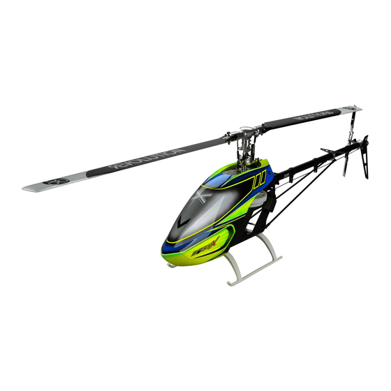
- Page 1 ® Instruction Manual Bedienungsanleitung ® Manuel d’utilisation Manuale di Istruzioni...
- Page 2 This product is not intended for use by children without direct adult supervision. Do not use with incompatible components or alter this product in any way outside of the instructions provided by Horizon Hobby, Inc. This manual contains instructions for safety, operation and maintenance.
-
Page 3: Table Of Contents
® ® elcome to the world of Blade Pro Series helicopter performance. If this is your fi rst helicopter building experience, there are a few things Over two decades of fl ying and design experience has gone into the you might want to get before you start unpacking parts. Many builders development of the Blade 700 X. -
Page 4: Tools Needed To Complete
Tools Needed To Complete • 1.5mm, 2mm, 2.5mm, 3mm and 4mm hex drivers • Pitch gauge • Ball link pliers • Metric calipers • Needle nose pliers • Petroleum-based, light viscosity lube • Phillips screwdriver • Medium cyanoacrylate (CA) • Wire cutter Required Items •... -
Page 5: Head Assembly (H)
Head Assembly (H) Step H1 Step H1 parts (bags H1 and H2) M4 X 25 Cap Head Shoulder Bolt (x2) M4 Locknut (x2) Step H2 parts (bags H1 and H2) M3 X 10 Cap Head Bolt Spindle Sleeve Step H2 Damper (x2) •... - Page 6 Head Assembly cont’d Step H4 parts (bag H4) Step H4 M3 X 14 Button Head Bolt (x2) M3 X 12 Button Head Bolt (x2) Control Ball (x2) • Loosely install bolts A and B before tightening. Step H5 parts (bag H5) Step H5 M3x12 Cap Head Bolt (x2) Washer 3 X 4 X .5 (x4)
- Page 7 Head Assembly cont’d Step H6 Step H6 parts (H6) M3 X 50 Control Rod (x2) M3 Ball Link Pushrod lengths 67mm Swash to blade grip link (x2) Anti-Rotation Pin Control Ball (x7)
-
Page 8: Frame Assembly (F)
Frame Assembly (F) NOTICE: Before assembly, plan your wire routing for the servos. At any point where the servo wire is going to pass through or cross the frame plates, use sandpaper to round the edge of the frame plate to prevent the wire from chafi ng. Step F1 parts (bags F1 and F2) Step F1 M3 X 8 Cap Head Bolt... - Page 9 Frame Assembly cont’d Step F3 Step F3 parts (bag F4) One-Way Sleeve M3 X 6 Button Head Bolts (x6) • Slide the mainshaft into position, then tighten all the frame screws. • A .5mm or 1mm shim may be added above the collar if needed.
- Page 10 Frame Assembly cont’d Step F5 parts (bag F5) Step F5 Head assembly M4 X 40 Cap Head Shoulder Bolt (x3) removed for clarity M3 X 8 Cap Head Bolt (x4) M3 Washer (x4) M4 X 4 Set Screw (x2) Pinion Helical Mod 1, 13T, 6mm Step F6 parts (bag F6) M3 X 8 Cap Head Bolt (x3)
- Page 11 Frame Assembly cont’d Step F6 contd. Elevator servo Step F7 Step F7 parts (bag F6) Tail servo M3 X 16 Cap Head Bolt (x4) M3 Washer (x4) Servo Spacer (x2) Tail Servo Nut (x2)
- Page 12 Frame Assembly cont’d Step F9 parts (bag F7) Step F9 M3 X 8 Cap Head Bolt (x4) Step F10 parts (bag F8) Step F10 Hexagonal Posts (x6) Jack Shaft Radial Bearing 12 X 18 X 4 (x2) Radial Bearing 5 X 10 X 4 (x2) Gear Pin (x2) M3 X 4 Set Screw (x2)
- Page 13 Frame Assembly cont’d Step F11 Step F11 parts (bag F8) M3 X 8 Cap Head Bolt (x12) Step F12 Step F12 parts (bag F9) M3 X 8 Cap Head Bolt (x4) Double-sided AR7200BX Alignment foam tape 90° Front viewed from top...
-
Page 14: Tail Assembly (T)
Tail Assembly (T) Step T1 parts (bag T1) Step T1 M3 X 6 Button Head Bolt (x2) Step T2 parts (bag T2) Step T2 M3 X 4 Set Screw Gear Pin Step T3 parts (bag T3) Step T3 Small inner diameter race M3 X 8 Cap Head Bolt (x2) Bearing cage Control Ball (x2) - Page 15 Tail assembly cont’d Step T4 Step T4 parts (bag T4) M3 X 6 Button Head Bolt (x2) Bell Crank Bolt (x2) Control Ball Flanged Bearing M3 X 6 X 2.5 (x2) Washer M3 X 4 X .5 (x2) viewed from the back Step T5 Step T5 parts (bag T3) M3 X 16 Cap Head Shoulder Bolt (x2)
- Page 16 Tail assembly cont’d • Glue the torque tube bearings in place by placing a Step T6 thin bead of CA on the torque tube at the given loca- tions (278mm, 300mm), then slide the bearings onto the CA. Do not allow CA to get into the bearings. 278 mm 300 mm Step T7 parts (bags T5 and T6)
- Page 17 Tail assembly cont’d Step T8 parts (T7, T8, and T9) Step T8 Tail Servo Neutral Position M3 X 8 Cap Head Bolt M4 X 8 Low Cap Head Bolt M3 X 6 Button Head Bolt (x2) M3 X 25 Cap Head Shoulder Bolt (x4) M3 X 28 Cap Head Shoulder...
-
Page 18: Esc And Battery Tray Assembly
ESC and Battery Tray Assembly Step ESC parts (bag F10) Hook and loop strap Hexagonal Post (x2) Battery Tray Post (x2) M3 X 8 Cap Head Bolt (x6) M2.5 X 6 Counter Sunk Bolt (x2) M3 X 14 Button Head Bolt (x2) M3 X 14 Cap Head Bolt (x2) Canopy Spacer (x2) Rubber Canopy Standoff (x2) - Page 19 ESC and Battery Tray Assembly cont’d Loop material Hook material Hook and loop straps...
-
Page 20: Main Rotor Installation
Main Rotor Installation Main Rotor parts (bag H3) M5 X 28 Cap Head Shoulder Bolt (x2) M5 Lock Nut (x2) • The rotor blades should be tight enough to hold their position if you hold the helicopter sideways, but loose enough to swing freely if you move the helicopter and stop abruptly. -
Page 21: Motor Direction Test
DO NOT use trim to assist in holding the Blade 700X in a desired position. The AR7200BX Flybarless Stabilization WARNING: Only use Blade 700 X approved carbon fi ber main blades. -
Page 22: Blade Tracking
Blade Tracking WARNING: Always maintain a safe distance of at least 13 meters 2. Watch the movement at the blade tips. Both blades should travel in the (45 feet) when checking the main rotor blade tracking. same plane. 3. If one blade tip appears to be higher than the other, land the helicopter, To check the blade tracking: disconnect the fl... -
Page 23: Troubleshooting Guide
Blade 700 X Troubleshooting Guide Problem Possible Cause Solution The helicopter was moved during initialization Lay the helicopter on its side during initialization if windy The transmitter is powered off Power on the transmitter AR7200BX will not initialize Center elevator, aileron and rudder controls. Make sure the throttle Controls are not centered is at idle Power off transmitter, move transmitter a larger distance from air-... -
Page 24: Limited Warranty
(iii) modifi cation of or to is not responsible for merchandise until it arrives and is accepted at our facility. any part of the Product, (iv) attempted service by anyone other than a Horizon Hobby An Online Service Request is available at http://www.horizonhobby.com/content/_ authorized service center, (v) Product not purchased from an authorized Horizon service-center_render-service-center. -
Page 25: Warranty And Service Contact Information
Harlow, Essex, CM18 7NS, United Kingdom +44 (0) 1279 641 097 Horizon Technischer Service service@horizonhobby.de Christian-Junge-Straße 1 Germany 25337 Elmshorn, Germany Sales: Horizon Hobby GmbH +49 (0) 4121 2655 100 infofrance@horizonhobby.com Service/Parts/Sales: 11 Rue Georges Charpak France Horizon Hobby SAS... - Page 26 Exploded View (Battery Tray) / Explosionszeichnung Akkuhalter / Vue éclatée (Platine de fi xation de batterie) / Vista esplosa (Supporto batteria)
- Page 27 Exploded View (Head/Tailcase) / Explosionszeichnung (Rotorkopf / Heckrotorgehäuse) / Vue éclatée (Tête et Anticouple) / Vista esplosa (Testa/Scatola di coda)
- Page 28 Exploded View (Frame Assembly) / Explosionszeichnung (Chassis) / Vue éclatée (Assemblage du châssis) / Vista esplosa (Gruppo telaio) 61 62 63 64...
- Page 29 Exploded View (Tailboom Assembly) / Explosionszeichnung (Heckausleger) / Vue éclatée (Assemblage de la poutre) / Vista esplosa (Gruppo tubo coda)
-
Page 30: Parts List / Ersatzteile / Pièces De Rechange / Pezzi Di Ricambio
Parts List / Ersatzteile / Pièces de rechange / Pezzi di ricambio Part # English Deutsch Français Italiano BLH5701 Main Rotor Grip Set: 700 X Blade 700 X: Rotorblatthalterset 700 X - Pieds de pales principales Set portapale rotore principale: 700 X 700 X - Leviers de pieds de pales BLH5702 Main Grip Arms: 700 X... -
Page 31: Optional Parts / Optionale Bauteile / Pièces Optionnelles / Pezzi Opzionali
Bloccaggio testa 3 pale: 700 X tripale 700 X - Support en métal de module de BLH5735A Metal FBL Unit Mount: 700 X” Blade 700X : Metallhalter FBL Einheit Supporto metallo per unità FBL: 700 X” contrôle FBL Blade 700X : Metall Taumelscheiben- BLH5732A Metal Anti-Rotation Bracket: 700 X 700 X - Guide anti-rotation en métal... - Page 32 ©2013 Horizon Hobby, Inc. Blade, E-fl ite, Dynamite, Revolution, EC5, Celectra, DSM, DSM2, DSMX, AirWare, ModelMatch and the Horizon Hobby logo are trademarks or registered trademarks of Horizon Hobby, Inc. The Spektrum trademark is used with permission of Bachmann Industries, Inc.
Need help?
Do you have a question about the Blade 700X and is the answer not in the manual?
Questions and answers