Table of Contents
Advertisement
For machines beginning with serial no. 84000
thru 99999 and serial no. R1000 and above
Basic
With (PR22)
Model
22" Prewash
44KB
44KPRB
54KB
54KPRB
44WS
66WS
KL44
KL66
March, 2005
P.O. Box 4149
Winston-Salem, North Carolina 27115-4149
336/661-1556
Fax: 336/661-1660
With (PR36)
36" Prewash
PR36/44KB
PR36/54KB
PR36/44WS
PR36/KL44
www.championindustries.com
Technical Manual
Single Tank
Rack Conveyor
with/without Prewash
With (FFPR26)
26" Front Feed
Prewash
FFPR26/44KB
FFPR26/54KB
FFPR26/44WS
FFPR26/KL44
Machine Serial No.
112844
P/N
Manual
Jordan Station, Ontario, Canada L0R 1S0
905/562-4195
Rev. I
2674 N. Service Road
Fax: 905/562-4618
Advertisement
Table of Contents

Related Manuals for Champion 44KB


Summary of Contents for Champion 44KB
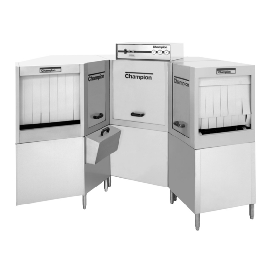
- Page 1 99999 and serial no. R1000 and above Single Tank Rack Conveyor with/without Prewash With (FFPR26) Basic With (PR22) With (PR36) 26" Front Feed Model 22" Prewash 36" Prewash Prewash 44KB 44KPRB PR36/44KB FFPR26/44KB 54KB 54KPRB PR36/54KB FFPR26/54KB 44WS 66WS PR36/44WS FFPR26/44WS KL44...
- Page 2 Control Cabinet Top of Machine Machine Data Plate with Model No., Serial No., Voltage and Phase is located on the right or left Left to Right side of the Control Cabinet Model Shown COPYRIGHT © 2005 by Champion Industries, Inc.
-
Page 3: Revision History
REVISIONS Revision History The revisions listed below cover machine design changes prior to the publication of this manual, P/N 112844, dated June, 1998. Revision Revised Serial Number Comments Date Pages Effectivity 04/01/93 — 84565 Redesign of cradle, replaced cradle roller with slide 04/01/93 —... - Page 4 REVISIONS Revision History Revision Revised Serial Number Comments Date Pages Effectivity 10/30/98 84000- Issue of new manual and new parts replacement lists & above Supersedes previous manual P/N 110874 beginning with date January 1989 thru June 1993. 12/3/99 142,144 R1649 Added 7CR, 120VAC Hold-in relay to control cabinet circuit to maintain power to booster circuit.
-
Page 5: Table Of Contents
CONTENTS CONTENTS Page REVISION HISTORY ........................WARRANTY ..........................vi KEY COMPONENTS ........................INTRODUCTION .......................... GENERAL............................INSTALLATION ..........................Unpacking .......................... Electrical Connections ......................Plumbing Connections ......................Ventilation Connections ...................... Chemical Connections ......................Curtain Locations ........................ Completing Installation ...................... OPERATION ............................ MAINTENANCE ..........................11 Maintenance Schedule ...................... - Page 6 CONTENTS LIST OF FIGURES (Cont.) Figure 11 — Magnetic Switch and Magnet .................. 24 Figure 12 — Rinse-Saver Switch Mechanism ................24 Figure 13 — Crank Assembly ......................25 Figure 14 — Conveyor Drive Assembly ..................25 Figure 15 — View of Load End of Machine ................26 Figure 16 —...
- Page 7 CONTENTS Figure 52 — Tank (PR22) (S/N 84565 and above) ..............118 Figure 53 — Tank (PR36) (S/N 84565 and above) ..............120 Figure 54 — Tank (FFPR26) (S/N 84565 and above) ..............122 Figure 55 — Drain Unit and Screens Wash Tank (S/N 84565 and above)........124 Figure 56 —...
-
Page 8: Warranty
Champion’s obligation with respect to labor associated with any repairs shall end (a) 120 days after shipment, or (b) 90 days after installation, whichever occurs first. In the event that Champion elects to repair, the labor and work to be performed in connection with the warranty shall be done during regular working hours by a Champion authorized service technician. -
Page 9: Key Components
KEY COMPONENTS Rack Conveyor Key Component Locations (Right to Left Electrical Machine Shown) Pressure Gauge Pressure Reducing Valve, PRV, (Factory Line Strainer Top Mounted Control Cabinet installed on machines with boosters) Vacuum Breaker Solenoid Valve Temperature Gauges Conveyor Crank and Crosshead Control Roller Assembly Transformer... -
Page 10: Introduction
All information, illustrations and specifications contained in this manual are based upon the latest product information available at the time of publication. Champion constantly improves its prod- ucts and reserves the right to make changes at any time or to change specifications or design with- out notice and without incurring obligation. -
Page 11: General
Single tank with 26" Front Feed Prewash .... FFPR26/54KB, FFPR26/44WS, FPR26/KL44 FFPR26/44KB • The 44KB and 54KB basic models, along with their respective prewash options, are high tem- perature (180˚F/82°C final rinse) sanitizing models. • The 44WS models, along with their respective prewash options, are water and energy saving, high temperature (180˚F/82°C final rinse) sanitizing models. - Page 12 GENERAL This Page Intentionally Left Blank...
-
Page 13: Installation
INSTALLATION INSTALLATION Unpacking CAUTION: Care should be taken when lifting the machine. The piping under the base can be damaged. Remove the dishwasher front panels if lifting from the front with a forklift. 1. Immediately after unpacking your machine, inspect for any shipping damage. If damage is found, save the packing material and contact the carrier upon receipt of the machine. -
Page 14: Plumbing Connections
3. If the incoming hot water supply pressure exceeds 25 psi [173 kPa], a PRV must be installed and set to 20-22 psi [138-151 kPa]. The PRV may be purchased from Champion or supplied by others. 4. Install a manual shut-off valve in the steam and water supply lines to accommodate servicing the machine. -
Page 15: Curtain Locations
INSTALLATION Curtain Locations 1. Refer to the illustrations below and hang the curtains as shown. J-hooks are located in the corners of each section to accept the curtain rods. • Standard long curtain 24" x 20-1/4" [610mm x 515mm] • High hood long curtain 24"... -
Page 16: Operation
OPERATION OPERATION PROCEDURE... - Page 17 OPERATION...
- Page 18 5. When tanks are full, check wash tank temperature gauge. Minimum wash temperatures are: • KL44, KL66 - 140°F/60°C • 44KB, 54KB, 44WS - 160°F/71°C • 44KPRB, 54KPRB, 66WS - 160°F/71°C 6. Press the START button on the control cabinet. Only the conveyor will start. The pumps WILL NOT OPERATE until the first rack enters the machine.
-
Page 19: Maintenance
MAINTENANCE MAINTENANCE The efficiency and life of your machine is increased by regularly scheduled preventive maintenance. A well maintained machine gives better results and service. An investment of a few minutes of daily maintenance will be worthwhile. The best maintenance you can provide is to keep your machine clean. Components that are not regularly cleaned and flushed will clog and become inoperative. -
Page 20: Deliming
MAINTENANCE • Weekly (Cont.) 6. Straighten a paper clip and use it to clear each rinse nozzle. 7. Inspect pawl bars and drive assembly for wear and freedom of travel. 8. Check float switches in tank for freedom of travel. 9. -
Page 21: Troubleshooting
Wash tank water temperature Incoming water temperature is low when in use at machine too low ......Raise temperature to: 140°F/60°C for 44KB, 54KB, 44WS, 44KPRB, 54KPRB, 66WS 120°F/49°C for KL44, KL66 Defective thermometer ...... Check or replace Defective thermostat ......Check for proper setting or replace Defective heater element .... - Page 22 TROUBLESHOOTING CONDITION CAUSE SOLUTION Insufficient pumped spray Clogged pump intake screen....Clean pressure Clogged spray pipe ......Clean Scrap screen full ........ Must be kept clean and in place Low water level in tank...... Check drain and overflow tube Pump motor rotation incorrect ..Reverse connection between L1 and L2 in control cabinet (3 phase only) Defective pump seal ......
-
Page 23: Electrical Service
ELECTRICAL SERVICE ELECTRICAL SERVICE Fuse Blocks—120VAC Control Voltage Two fuse blocks, located in the center rear of the main control cabinet protect the main control transformer. Each fuse block holds a fuse. The fuses are marked 1FU and 2FU on the electrical schematic. To Replace the fuse: 1R004 •... -
Page 24: Figure 3 Pump Timer
ELECTRICAL SERVICE Pump Timer 1R006 1R007 Refer to Fig. 3 The automatic timer located in the left center of the control cabinet is set at the factory. The Pump Timer controls the amount of time that the pumps will run before the last rack enters the load end of the dishwasher tunnel. -
Page 25: Figure 4 - Dual Float Switch
ELECTRICAL SERVICE ELECTRICAL SERVICE (Cont.) 1R008 Automatic Fill/Low Water Heat Protection Dual Float Switches – Refer to Fig. 4 Each tank contains a dual float. The device consists of an angled stem containing two reed switches. Two stainless steel ball floats slide over the stem and are free to move up and down. -
Page 26: Figure 5 - Tank Heat Thermostats
ELECTRICAL SERVICE ELECTRICAL SERVICE (Cont.) 1R009 Thermostat Locations and Adjustments Control Thermostat Refer to Fig. 5 Electric tank heat is controlled by two thermostats. 1. The control thermostat which regulates the temperature. 2. The high limit thermostat which protects from overheating. Location: High limit Both thermostats are located on front of tank, inside a black... - Page 27 ELECTRICAL SERVICE ELECTRICAL SERVICE (Cont.) Heater Element Wiring – Booster Tank and Wash Tank Heater Elements Refer to the illustrations and follow the steps below to properly install terminal jumpers and to make line power connections to a replacement element. Step 1.
- Page 28 6. Motor rotation can be reversed by switching L1 and L2 on 3 phase motors. Single phase motor rotation cannot be reversed 7. Replacement motors are available as complete assemblies. 8. Champion cannot provide replacement bearings, stators, or rotors for motor repair parts.
- Page 29 ELECTRICAL SERVICE Dual Float Switches – Troubleshooting: The dual float controls fill and heat circuits. Identifying a Dual Float Problem: The most common trouble conditions associated with a dual float failure are: 1. The tank fills constantly. 2. The tank heat will not come on. Inspect the Dual Float: 1.
-
Page 30: Figure 8 - Front View Typical 40°F/22°C Rise Booster, One Tank 38 Kw Shown
ELECTRICAL SERVICE Electric Booster Heater — Element Installation Refer to Fig. 8 and Fig. 9 1R012 Champion built-in boosters are constructed of stainless steel and have locations for three electric booster heater elements. 1. The two booster configurations for rack... -
Page 31: Mechanical Service
MECHANICAL SERVICE MECHANICAL SERVICE Pump Seal Replacement: Gasket Pump Flange Impeller Volute WARNING: Disconnect all Seal Assy power to the Washer Bolt machine at the main power source and Water place a tag at Slinger the disconnect switch to show that work is being done on the circuit. -
Page 32: Figure 10 - Idle Pump Switch Assembly
MECHANICAL SERVICE MECHANICAL SERVICE (Cont.) Idle Pump and Rinse-Saver Switch Assemblies 1R014 Idle Pump Switch Assembly – Refer to Fig. 10. The idle pump switch, also called the rack switch is located on the load end of the conveyor track. It is made up of a lever mechanism, a magnet, and a magnetic reed switch. -
Page 33: Conveyor Drive Assembly
MECHANICAL SERVICE Conveyor Drive Assembly 1R017 Refer to Fig. 14. The conveyor drive assembly is made up of a Crosshead Roller crank assembly, a clutch assembly, gear reducer, and 1/4 HP motor. Screw C Crank Assembly – Refer to Fig. 13. The crank Washer assembly mounts inside the dish- washer hood and is made up of a... - Page 34 MECHANICAL SERVICE 1R019 Drive Clutch Replacement – • Turn off all power to the machine and remove the load end curtain. Refer to Fig. 15. Lift Track and Cradle Up 1. Remove (Screw A), the 10-32 x 3/8" flat head bracket retaining screw located slightly Screw A forward of the idle pump switch...
- Page 35 INSTRUCTIONS KIT P/N 407400 I. Introduction Champion Industries offers a table limit switch as an option to protect the dishwasher conveyor system from jams caused by dishracks backing up at the unload end of the dishtables. These instructions provide the servicer with a step-by-step method for installing and wiring the table limit switch on a rack conveyor dishwasher.
- Page 36 MECHANICAL SERVICE B. Additional Materials Required for Installation (Supplied by the Installer) (*) Ft. of flexible non-metallic liquid tight 1/2" conduit (*) Ft. of #14 gauge wire (2 wires & a ground required) 6" [152mm] (3) Ring terminals #6 stud size (1) Ring terminal 1/4-20 stud size (2) Wire nuts (1) Straight 1/2"...
- Page 37 IV. Wiring and Final Mounting of the Table Limit Switch Assembly Note 1: Wiring should be made in accordance with local electrical codes. Note 2: Champion recommends a ground wire from the switch to the junction box. A. Locating and Wiring of Junction Box 1.
- Page 38 MECHANICAL SERVICE 7. Connect the proper conduit fitting to the table limit switch. Route the #14 gauge wires to the switch and refer to Fig. F for the proper terminal designations. Fig. F 8. Connect conduit wire 7 to the COM (Common) terminal of the switch terminal block. Connect conduit wire 8 to the NC (Normally Closed) terminal of the switch terminal block.
-
Page 39: Replacement Parts
REPLACEMENT PARTS REPLACEMENT PARTS... - Page 40 REPLACEMENT PARTS 1R022 TANK Figure 18 – Conveyer Drive Assembly...
- Page 41 Motor, 1/4-HP Drive (415V-50Hz-3Ph) ..........180240 Motor, 1/4-HP Drive (575V-60Hz-3Ph) ..........100458 Sheave (AK74) 3/4" Bore (44WS) ............103162 Sheave (AK25) 1/2" Bore (44KB, 54KB, KL44) ........100801 Belt - 4L370 (44WS, 66WS)..............100797 Belt - 4L340 (44KB, 54KB) ..............100796 Belt - 4L330 (KL44, KL66) ..............
- Page 42 REPLACEMENT PARTS Figure 19 – Track and Cradle Assembly (For machines beginning with S/N 84565 and above except KL-44/66 beginning with S/N 90513 and above)
- Page 43 100141 Nut, grip (1/4-20) ..................204513 Pawl......................110857 Shoulder bolt ..................316899 Cradle (44KB, 44WS, KL44) (Beginning with S/N 84565) ....316900 Cradle (54KB) (Beginning with S/N 84565) .......... 100142 Nut, grip (5/16-18) .................. 315278 Support – Front (RH) ................
- Page 44 REPLACEMENT PARTS 1R025 Figure 20 – Track and Cradle Assembly – PR22, PR36 (All S/N's) (PR36 Shown)
- Page 45 REPLACEMENT PARTS TRACK AND CRADLE ASSEMBLY (PR22, PR36) (All S/N's) (PR36 Shown) Fig. 20 Part Item No. Part Description Qty. 311651 Track (PR22) .................... 313117 Track (PR36) ..................100194 Nut, grip (10-32) (PR22) ................ 100194 Nut, grip (10-32) (PR36) ................ 111296 Screw (10-32 x 3/8") Flat hd (PR22) ............
- Page 46 REPLACEMENT PARTS 1R026 Figure 21 – Track and Cradle Assembly (KL-44/66 Only) (For machines beginning with S/N 90513 and above)
- Page 47 REPLACEMENT PARTS TRACK AND CRADLE ASSEMBLY (KL-44/66 ONLY) (For machines beginning with S/N 90513 and above) Fig. 21 Part Item No. Description Qty. 311650 Track (KL44) .................... 111296 Screw 10-32 x 3/8" .................. 100194 Nut, Grip 10/32 ..................100073 Screw 1/4-20 x 1/2" .................. 100141 Nut, Grip 1/4-20 ..................
- Page 48 REPLACEMENT PARTS 1R027 Figure 22 – Motor and Pump Assembly (Wash and Prewash) (All S/N's)
- Page 49 REPLACEMENT PARTS MOTOR AND PUMP ASSEMBLY (Wash and Prewash) (All S/N's) Fig. 22 Part Item No. Part Description Qty. — Machines beginning with S/N 79656 thru S/N 86855 were built with a one piece pump volute (See detail top of page 40). This design is no longer available and is replaced with the kits listed below.
- Page 50 REPLACEMENT PARTS MOTOR/PUMP ASSEMBLY (Cont.) (Wash and Prewash) Fig. 22 Part Item No. Part Description Qty. 100736 Bolt (1/4-20 X 3/4") Hex hd ..............111964 Clamp, discharge pump hose..............102504 Plug (1/2" NPT) Brass................112338 Gasket, Pump Suction Flange ..............112379 Flange, suction machined ................
- Page 51 REPLACEMENT PARTS MOTOR AND PUMP ASSEMBLY (Cont.) (Wash and Prewash) Fig. 22 Part Item No. Part Description Qty. Pump Assemblies – ORIENTATION “B” — 451361 Pump Assy. lHP, 208-240V/60Hz/lPH (Includes items 1-2, 9, 15-26, 27, 29-32, 34-39) ........— 451615 Pump Assy.
- Page 52 REPLACEMENT PARTS 1R028 TANK BOTTOM STUD WELDED TO TANK BOTTOM Figure 23 – Idle Pump Mechanism (All S/N's)
- Page 53 Reed Switch Aleph .................. 104971 Nut, grip (6-32) ..................— 408221 Idle Pump Mechanism Assy (R-L 44KB, 44WS, KL44, 54KB, PR36) (R-LPR26) (includes items 1-10) ........— 408220 Idle Pump Mechanism Assy (L-R 44KB, 44WS, KL44, 54KB, PR36) (R-L PR26) (includes items 1-10) ........
- Page 54 REPLACEMENT PARTS 1R029 TANK BOTTOM STUD WELDED TO TANK BOTTOM Figure 24 – Idle Pump Switch (FFPR26 Only) (R-L Shown) (All S/N's)
- Page 55 REPLACEMENT PARTS IDLE PUMP SWITCH (FFPR26 Only) (R-L Shown) (All S/N's) Fig. 24 Part Item No. Part Description Qty. 111029 Cam ......................107137 Bolt (10-32 x 7/8") Hex hd ..............314093 Support, pivot arm .................. 315181 Stiffener, (R-L direction machine only) ..........315182 Stiffener, (L-R direction machine only) ..........
- Page 56 REPLACEMENT PARTS 1R030 Rear of Hood Tank Bottom Figure 25 – Wash System Assembly (For machines prior to S/N 84565)
- Page 57 REPLACEMENT PARTS WASH SYSTEM ASSEMBLY (For machines prior to S/N 84565) Fig. 25 Part Item No. Part Description Qty. 108846 Quick Coupler #3 ..................108416 Quick Coupler #2 ..................108847 Quick Coupler #1 ..................312623 Standpipe (R to L) ..................313212 Bracket, Stand Pipe ..................
- Page 58 REPLACEMENT PARTS 1R031 REAR HOOD TANK BOTTOM Figure 26 – Wash System Assembly (PR22, FFPR26) (For machines prior to S/N 84565)
- Page 59 REPLACEMENT PARTS WASH SYSTEM ASSEMBLY (PR22, FFPR26) (For machines prior to S/N 84565) Fig. 26 Part Item No. Part Description Qty. 108648 Quick Coupler (PR22) Upper & Lower ..........111088 Quick Coupler (FFPR26) (R-L Lower)(L-R Upper)........ 111089 Quick Coupler (FFPR26) (L-R Lower)(R-L Upper)........ 100073 Screw, 1/4-20 x 1/2 Truss Head..............
- Page 60 REPLACEMENT PARTS 1R032 REAR HOOD TANK BOTTOM Figure 27 – Wash System Assembly (PR36) (For machines prior to S/N 84565)
- Page 61 REPLACEMENT PARTS WASH SYSTEM ASSEMBLY (PR36) (For machines prior to S/N 84565) Fig. 27 Part Item No. Part Description Qty. 108846 Quick Coupler #3 ..................108416 Quick Coupler #2 ..................108847 Quick Coupler #1 ..................313575 Stand Pipe, Standard ................313212 Bracket, Stand Pipe ..................
- Page 62 REPLACEMENT PARTS 1R033 Figure 28 – Wash System Assembly (For machines beginning with S/N 84565 thru 89276)
- Page 63 REPLACEMENT PARTS WASH SYSTEM ASSEMBLY (For machines beginning with S/N 84565 thru 89276) Fig. 28 Part Item No. Part Description Qty. 408126 Manifold Assy, upper................111456 Gasket, manifold ..................106482 Washer, lock (1/4") split ................100736 Bolt (1/4-20 x 3/4") Hex hd ..............100073 Screw (1/4-20 x 1/2") Truss hd ..............
- Page 64 REPLACEMENT PARTS 1R034 18 19 Figure 29 – Wash System Assembly (PR22, FFPR26) (For machines beginning with S/N 84565 thru 89276)
- Page 65 REPLACEMENT PARTS WASH SYSTEM ASSEMBLY (PR22, FFPR26) (For machines beginning with S/N 84565 thru 89276) Fig. 29 Part Item No. Part Description Qty. 107137 Bolt (10-32 x 7/8") Hex hd ..............111454 Locking plate, manifold ................111505 O-ring......................316794 Flange Assy, upper .................. 111456 Gasket, flange ..................
- Page 66 REPLACEMENT PARTS 1R035 15° REAR HOOD TANK BOTTOM Figure 30 – Wash System Assembly (PR36) (For machines beginning with S/N 84565 thru 89276)
- Page 67 REPLACEMENT PARTS WASH SYSTEM ASSEMBLY (PR36) (For machines beginning with S/N 84565 thru 89276) Fig. 30 Part Item No. Part Description Qty. 316688 Manifold Assy, upper ................111456 Gasket, manifold ..................106482 Washer, lock (1/4") Split ................ 100736 Bolt (1/4-20 x 3/4") Hex hd ..............100073 Screw (1/4-20 x 1/2") Truss hd ..............
- Page 68 REPLACEMENT PARTS 1R036 Figure 31 – Wash System Assembly (For machines beginning with S/N 89277 and above)
- Page 69 REPLACEMENT PARTS WASH SYSTEM ASSEMBLY (For machines beginning with S/N 89277 and above) Fig. 31 Part Item No. Part Description Qty. 408126 Manifold Assy. 44/54KB ................111456 Gasket Manifold ..................106482 Washer Lock 1/4" Split ................100736 Bolt 1/4-20 x 3/4 Hex Head ..............100073 Screw 1/4-20 x 1/2 Truss Head ..............
- Page 70 REPLACEMENT PARTS 1R037 Figure 32 – Wash System Assembly (PR22, FFPR26) (For machines beginning with S/N 89277 and above)
- Page 71 REPLACEMENT PARTS WASH SYSTEM ASSEMBLY (PR22, FFPR26) (For machines beginning with S/N 89277 and above) Fig. 32 Part Item No. Part Description Qty. 112240 Plug, Debossed Spraypipe ................ 104414 O-ring 1" ....................321471 Spraypipe ....................107137 Bolt 10-32 x 7/8" HH ................111454 Locking Plate, Manifold ................
- Page 72 REPLACEMENT PARTS 1R038 Figure 33 – Wash System Assembly (PR36) (For machines beginning with S/N 89277 and above)
- Page 73 REPLACEMENT PARTS WASH SYSTEM ASSEMBLY (PR36) (For machines beginning with S/N 89277 and above) Fig. 33 Part Item No. Part Description Qty. 316688 Manifold Weld 3 Hole ................111456 Gasket, Manifold ..................106482 Washer Lock 1/4" Split ................100736 Bolt 1/4-20 x 3/4" HH ................100073 Screw 1/4-20 x 1/2"...
- Page 74 REPLACEMENT PARTS 1R039 Figure 34 – Outside Rinse Piping With Electric Booster (Prior to Serial Number R1529)
- Page 75 311694 Bracket, piping support ................107550 Valve, pressure reducing (3/4 NPT) Brass ..........110768 Strainer, line (3/4 NPT) Brass ..............107380 Tubing, copper (44KB) ................107380 Tubing, copper (54KB) ................109885 Valve, solenoid (1/4 NPT) (120V coil) ............ — 111172 Repair kit, (1/4 ") Solenoid valve ............
- Page 76 REPLACEMENT PARTS 1R039r02 Figure 35 – Outside Rinse Piping With Electric Booster (After Serial Number R1530)
- Page 77 REPLACEMENT PARTS OUTSIDE RINSE PIPING WITH ELECTRIC BOOSTER AFTER SERIAL NUMBER R1530 Fig. 35 Part Item No. Part Description Qty. 101259 Pipe Plug 1/8 NPT Brass ................105976 Bushing, Reducing (3/4 NPT x 1/8 NPT) ..........100599 Cross (3/4 NPT) Brass................102392 Bushing, Reducing (3/4 NPT x 1/2 NPT) Brass ........
- Page 78 REPLACEMENT PARTS OUTSIDE RINSE PIPING WITH ELECTRIC BOOSTER AFTER SERIAL NUMBER R1530 (cont.) Fig. 35 Part Item No. Part Description Qty. 102422 Elbow (1/4 NPT x 90°) Brass (PR22) ............110134 Nipple (1/4 NPT x 2 1/2) Brass (PR22) ..........107069 Breaker, vacuum (1/4 NPT) Brass (bronze) ..........
- Page 79 THIS PAGE INTENTIONALLY LEFT BLANK...
- Page 80 REPLACEMENT PARTS 1R040r02 Figure 36 – Fill & Outside Rinse Piping With No Electric Booster or With Steam Booster (All S/N’s)
- Page 81 Screw (1/4-20 x 1/2") Truss hd .............. 311694 Bracket, piping support ................110768 Line strainer (3/4 NPT) Brass ..............107380 Tubing, copper (44KB) ................107380 Tubing, copper (54KB) ................109885 Valve, solenoid (1/4 NPT) (Prior to S/N R2435) ........—...
- Page 82 REPLACEMENT PARTS FILL & OUTSIDE RINSE PIPING WITH NO BOOSTER OR WITH STEAM BOOSTER (cont.) (All S/N's) Fig. 36 Part Item No. Part Description Qty. 102422 Elbow (1/4 NPT x 90°) Brass ..............110134 Nipple (1/4 NPT x 2-1/2") Brass.............. 107069 Vacuum breaker (1/4 NPT) Brass (bronze) ..........
- Page 83 THIS PAGE INTENTIONALLY LEFT BLANK...
- Page 84 REPLACEMENT PARTS 1R041 Figure 37 – Fill & Outside Rinse Piping With No Booster (KL44, KL66) (All S/N’s)
- Page 85 Valve, pressure reducing (3/4 NPT) Brass (Not installed at factory) ..— 110768 Strainer, line (3/4 NPT) Brass ..............107380 Tubing, copper (44KB) ................107380 Tubing, copper (54KB) ................109885 Valve, solenoid (1/4 NPT) (Prior to S/N R2436) ........—...
- Page 86 REPLACEMENT PARTS FILL & OUTSIDE RINSE PIPING WITH NO BOOSTER (KL-44, KL-66) ALL S/N’S (cont.) Fig. 37 Part Item No. Part Description Qty. 101262 Nipple (1/4 NPT x 1 1/2) Brass .............. 102388 Bushing, Reducing 1/2 x 1/4 Brass (After S/N R2436) ......100947 Nipple, close 1/4 NPT Brass (Not Shown) (After S/N R2436) ....
- Page 87 REPLACEMENT PARTS THIS PAGE INTENTIONALLY LEFT BLANK...
- Page 88 REPLACEMENT PARTS 1R042B Figure 38 – Fill & Outside Rinse Piping 44WS – With Electric Booster (For machines beginning with S/N 82305 and above)
- Page 89 REPLACEMENT PARTS FILL & OUTSIDE RINSE PIPING 44WS – WITH ELECTRIC BOOSTER (For machines beginning with S/N 82305 and above) Fig. 38 Part Item No. Part Description Qty. 101259 Pipe plug (1/8 NPT) Brass ..............105976 Bushing, reducing (3/4 NPT x 1/8 NPT) ..........102392 Bushing, reducing (3/4 NPT x 1/2 NPT) ..........
- Page 90 REPLACEMENT PARTS FILL & OUTSIDE RINSE PIPING 44WS – WITH ELECTRIC BOOSTER (cont.) (For machines beginning with S/N 82305 and above) Fig. 38 Part Item No. Part Description Qty. 102422 Elbow (1/4 NPT x 90° ) Brass..............107069 Vacuum breaker (1/4 NPT) Brass (bronze) ..........**—...
- Page 91 THIS PAGE INTENTIONALLY LEFT BLANK...
- Page 92 REPLACEMENT PARTS 1R043 Figure 39 – Fill & Outside Rinse Piping 44WS – No Booster and Steam Booster (For machines beginning with S/N 82305 and above)
- Page 93 REPLACEMENT PARTS FILL AND OUTSIDE RINSE PIPING 44WS NO BOOSTER AND STEAM BOOSTER (For machines beginning with S/N 82305 and above) Fig. 39 Part Item No. Part Description Qty. 101259 Pipe plug (1/8 NPT) Brass ..............105976 Bushing, reducing (3/4 NPT x 1/8 NPT) Brass ........100599 Cross (3/4 NPT) Brass ................
- Page 94 REPLACEMENT PARTS FILL AND OUTSIDE RINSE PIPING 44WS NO BOOSTER AND STEAM BOOSTER (cont.) (For machines beginning with S/N 82305 and above) Fig. 39 Part Item No. Part Description Qty. 101262 Nipple (1/4 NPT x 1-1/2) Brass (Prior to S/N R2435) ......102388 Bushing, Reducing 1/2 x 1/4 Brass (After S/N R2436) ......
- Page 95 THIS PAGE INTENTIONALLY LEFT BLANK...
- Page 96 REPLACEMENT PARTS TOP OF PREWASH HOOD PREWASH TANK Figure 40 – Cold Water Thermostat for Prewash Option (All S/N’s)
- Page 97 REPLACEMENT PARTS COLD WATER THERMOSTAT FOR PREWASH OPTION (All S/N’s) Fig. 40 Part Item No. Part Description Qty. 201669 Locknut (1/4 NPT) (Nickel Plated) ............100573 Locknut (1/4 NPT) Brass ................ 110135 Nipple (1/4 NPT x 7 1/4) Brass .............. 101261 Elbow, street (1/4 NPT x 90°) Brass ............
- Page 98 REPLACEMENT PARTS 1R045 HOOD TOP STUD WELDED TO TANK REAR OF HOOD TANK BOTTOM Figure 41 – Inside Rinse Piping and Rinse Drain-Off (KL-44/66 Only) (For machines beginning with S/N 90513 and above)
- Page 99 REPLACEMENT PARTS INSIDE RINSE PIPING AND RINSE DRAIN-OFF (KL-44/66 ONLY) (For machines beginning with S/N 90513 and above) Fig. 41 Part Item No. Part Description Qty. 100548 Locknut 3/4 NPT SST ................108620 Gasket Rinse Pipe ..................322372 Manifold, Final Rinse (Standard) ............205754 Pipe Final Rinse Upper ................
- Page 100 REPLACEMENT PARTS 1R046 HOOD TOP STUD WELDED TO TANK REAR OF HOOD TANK BOTTOM Figure 42 – Inside Rinse Piping and Rinse Drain-Off (Models KB, WS, KL) (For machines beginning with S/N 87575 and above)
- Page 101 Pipe Final Rinse, 44KB, KL44, 54KB, 44WS ........106734 Cap 1/2" Plastic ..................112022 Nozzle Spray Lower, 44KB, KL44, 54KB, 44WS ........311404 Manifold, Final Rinse (High Hood) 44KB, 44WS, 54KB ...... 315294 Support – Rinse Pipe ................311761 Screen, Drain Body .................. 315682 Restrictor, Drain ..................
- Page 102 REPLACEMENT PARTS 1R047 HOOD TOP STUD WELDED TO TANK REAR OF HOOD TANK BOTTOM Figure 43 – Inside Rinse Piping and Rinse Drain-Off (For machines prior to S/N 87575)
- Page 103 Rinse Pipe, upper & lower (44KB,KL44) ..........106734 Cap, rinse pipe ..................111519 Nozzle, final rinse (44KB, KL44, 54KB) ..........311404 Manifold, final rinse – (High-Hood) (44KB, 44WS, 54KB) ....315294 Support, rinse pipe .................. 311761 Screen, drain body ..................315682 Restrictor, drain ..................
- Page 104 REPLACEMENT PARTS 1R048 UNLOAD END OF TRACK STUDS WELDED TO TANK Figure 44 – Rinse Saver Mechanism (For machines prior to S/N 88123)
- Page 105 This style rinse saver mechanism is no longer available. Service replacement kits are listed below: Refer to pages 88-91 for component parts contained in the kits. — 900735 44KB, 44KPRB, 54KB, 54KPRB, KL44, 44WS, 66WS Machine direction L-R — 900736 44KB, 44KPRB, 54KB, 54KPRB, KL44, 44WS, 66WS...
- Page 106 REPLACEMENT PARTS 1R049 Figure 45 – Rinse Saver Mechanism (L-R Shown) (For machines beginning with S/N 88123 and above)
- Page 107 REPLACEMENT PARTS RINSE SAVER MECHANISM (L-R SHOWN) (For machines beginning with S/N 88123 and above) Fig. 45 Part Item No. Part Description Qty. 100754 Screw 10-32 x 1/2" Flat Head ..............100194 Nut Grip 10-32 ..................319302 Bracket, Rinse Switch Mounting.............. 106026 Washer 1/4 x 5/8 x 1/16 SST..............
- Page 108 REPLACEMENT PARTS 1R050 Figure 46 – Rinse Saver Mechanism (R-L Shown) (For machines beginning with S/N 88123 and above)
- Page 109 REPLACEMENT PARTS RINSE SAVER MECHANISM (R-L SHOWN) (For machines beginning with S/N 88123 and above) Fig. 46 Part Item No. Part Description Qty. 100754 Screw 10-32 x 1/2" Flat Head ..............100194 Nut Grip 10-32 ..................319302 Bracket, Rinse Switch Mounting.............. 106026 Washer 1/4 x 5/8 x 1/16 SST..............
- Page 110 REPLACEMENT PARTS 1R051 Track Figure 47 – Rinse Saver Mechanism (KL-44/66 Only) (For machines beginning with S/N 90513 and above)
- Page 111 REPLACEMENT PARTS RINSE SAVER MECHANISM (KL-44/66 ONLY) (For machines beginning with S/N 90513 and above) Fig. 47 Part Item No. Part Description Qty. 322554 Final Rinse Lever (R-L) ................322555 Final Rinse Lever (L-R) ................111026 Magnet SST ....................108954 Nut Grip 6-32 w/Nylon Insert ..............
- Page 112 REPLACEMENT PARTS 1R052A AFTER S/N R2559 FRONT OF HOOD Figure 48 – Doors, Curtains, Miscellaneous...
- Page 113 317345 Bracket, door catch (Prior to S/N R2558)..........— 325920 Bracket, door stop/catch combo (After S/N R2559) ......311303 Panel, front (44KB, KL44, 44WS, 54KB) ..........313292 Panel, front 10" (54KB) (Not shown) ............313036 Panel, end....................108578 Bracket, panel ..................
- Page 114 REPLACEMENT PARTS 1R053A TO WASH TANK PIPING AFTER S/N R2559 47 48 49 46 FRONT OF HOOD Figure 49 – Hood (PR22, PR36) (For machines prior to S/N 87575)
- Page 115 Replacement coil, solenoid valve (1/4" NPT) (120V coil) ...... 109909 Fitting, compression (1/4 NPT x 1/2") ............ 107315 Tubing, copper (1/2" O.D.) (44KB, 44WS, KL44) w/PR36 ....107315 Tubing, copper (1/2" O.D.) (54KB) w/PR36 .......... 107315 Tubing, copper (1/2" O.D.) (44KB, 44WS, KL44) w/PR22 ....
- Page 116 Bracket, magnet (PR36) ................104971 Nut, grip 6-32 (PR36) ................100212 Screw, 10-32 x 3/4" Truss Hd ..............317124 Chaseway, reed switch (PR36 w/ 44KB, KL44. 44WS) ......317126 Chaseway, reed switch (PR36 w/ 54KB)..........113721 Reed Switch Aleph (PR36) ..............100735 Bolt (1/4-20 x 5/8) Hex Head ..............
- Page 117 THIS PAGE INTENTIONALLY LEFT BLANK...
- Page 118 REPLACEMENT PARTS 1R054-B2 TO WASH TANK PIPING AFTER /SN R2559 47 48 49 46 FRONT OF HOOD Figure 50 – Hood (PR22, PR36) (For machines beginning with S/N 87575 and above)
- Page 119 Fitting, compression (1/4 NPT x 1/2") (Prior to S/N R2440)....111250 Fitting, compression 1/2 OD x 1/2 MPT Brass (After S/N R2441) ..107315 Tubing, copper (1/2" O.D.) (44KB, 44WS, KL44) w/PR36 ....107315 Tubing, copper (1/2" O.D.) (54KB) w/PR36 .......... 107315 Tubing, copper (1/2"...
- Page 120 Back plate, door switch (PR36)..............108578 Bracket, panel ..................317690 Table flange (Prior to S/N R2207) ............325492 Table Flange (KL44, 44KB, 44WS) (After S/N R2208 ......108042 Curtain, end (Standard) ................109588 Curtain, end (High-Hood) ................ 110856 Nut (1/4" NPT) Plug ................
- Page 121 THIS PAGE INTENTIONALLY LEFT BLANK...
- Page 122 REPLACEMENT PARTS 1R055B Figure 51 – Hood (FFPR26) (All S/N's)
- Page 123 Table flange (For machines prior to S/N 87575)........— 317690 Table flange (For machines beginning with S/N 87575 thru R2207) ..325942 Table flange (KL44, 44KB, 44WS) (After S/N R2208) ......108043 Curtain, center (Standard) ..............109589 Curtain, center (High-Hood) ..............
- Page 124 Fitting, compression 1/4 NPT x 1/2" (Prior to S/N R2435) ....111250 Fitting, compression 1/2 OD x 1/2 MPT Brass (After S/N R2436) ..107315 Tubing, copper (1/2" O.D.) (44KB, 44WS, KL44) ........ 107315 Tubing, copper (1/2" O.D.) (54KB) ............108578 Bracket, panel ..................
- Page 125 THIS PAGE INTENTIONALLY LEFT BLANK...
- Page 126 REPLACEMENT PARTS 1R056 Figure 52 – Tank (PR22) (For machines beginning with S/N 84565 and above)
- Page 127 Tee (1-1/2 NPT x 1-1/4 NPT x 1-1/4 NPT) Galvanized ......111113 Nipple, toe (1-1/4 NPT x 2") Galvanized ..........204979 Hose, drain, L-R (44KB, 44WS, KL44) ..........204980 Hose, drain, L-R (54KB) ................ 204973 Hose, drain, R-L (44KB, 44WS, KL44) ..........
- Page 128 REPLACEMENT PARTS 1R057 Figure 53 – Tank (PR36) (For machines beginning with S/N 84565 and above)
- Page 129 111060 Tee (1-1/2 NPT x 1-1/4 NPT x 1-1/4 NPT) Galvanized ......111113 Nipple, tee (1-1/4 NPT x 2") Galvanized ..........111117 Hose, drain, L-R (44KB, 44WS, KL44) ..........5 ft. 111117 Hose, drain, L-R (54KB) ................5 ft. 111117 Hose, drain, R-L (44KB, 44WS, KL44) ..........
- Page 130 REPLACEMENT PARTS 1R058 10 11 THERMOMETER LEAD (CALLED OUT IN CONTROL CABINET) TO WASH DRAIN Figure 54 – Tank (FFPR26) (For machines beginning with S/N 84565 and above)
- Page 131 Tee (l-1/2 NPT x 1-1/4 NPT x 1-1/4 NPT) Galvanized......111113 Nipple, toe (1-1/4 NPT x 2") Galvanized ..........107340 Clamp, hose (M28) .................. 111117 Hose, drain (44KB, KL44, 44WS) ............3 ft. 111117 Hose, drain (54KB) ................4 ft. —...
- Page 132 REPLACEMENT PARTS 1R059 29 30 Figure 55 – Drain Unit and Screens Wash Tank (For machines beginning with S/N 84565 and above)
- Page 133 Baffle, water, R-L (44KB, 44WS) (After S/N R1690) ......317036 Baffle, water, L-R (44KB) ..............325160 Baffle, water, L-R (KL44, 44KB, 44WS) (After S/N R1719) ....317039 Baffle, water, R-L (54KB)................ 325159 Baffle, water, R-L (54KB) (After S/N R2127) ........
- Page 134 REPLACEMENT PARTS 1R060 Tank Bottom Front of Tank Figure 56 – Drain Unit and Screens Wash Tank (For machines beginning with S/N 80677 thru S/N 84565)
- Page 135 Cam ......................111441 Spacer (9/32 x 1-3/4"................314112 Lever, drain ....................315177 Lift rod, overflow ..................314463 Overflow (7") (44KB, KL44, 44WS) ............111532 O-ring, overflow ..................112257 O-ring......................111034 Drain body ....................111059 Tee 1-1/4" x 1-1/4" x 1-1/2" Galvanized..........
- Page 136 REPLACEMENT PARTS 1R061 To Wash Drain See Fig. 52, pg. 118,Tank PR22 and Fig. 53, pg. 120, Tank PR36 for float switch and other tank parts Figure 57 – Drain Unit and Screens (PR22, PR36) (For machines beginning with S/N 80677 thru S/N 84565)
- Page 137 111060 Tee, 1-1/2" x 1-1/4" x 1-1/4" Galvanized ..........111113 Nipple, TOE 1-1/4" NPT x 2" Glavanized ..........204979 Hose, drain (44KB, 44WS, KL44) (L-R) ..........204980 Hose, drain (54KB) (L-R) ................ 204973 Hose, drain (44KB, 44WS, KL44) (R-L) ..........
- Page 138 REPLACEMENT PARTS 1R062 10 11 See Fig. 53, pg. 120, Tank FFPR26 for float switch and other tank parts Figure 58 – Drain Unit and Screens (FFPR26) (For machines beginning with S/N 80677 thru S/N 84565)
- Page 139 Drain body ....................111060 Tee, 1-1/2" x 1-1/4" x 1-1/4" Galvanized ..........111113 Nipple, TOE 1-1/4" NPT x 2" Glavanized ..........107340 Clamp, hose ....................204971 Hose, drain (44KB, 44WS, KL44) (L-R) ..........204974 Hose, drain (54KB) ................314294 Support, overflow ..................
- Page 140 REPLACEMENT PARTS 1R063 Figure 59 – Control Cabinet (For machines beginning with S/N 84000 and above)
- Page 141 317405 Cover, control cabinet 36" (44KB, 54KB, KL44, 44KPRB, 54KPRB, KL66) (Beginning with S/N 85303 and above) ...... 110866 26" Decal (44KB, 54KB, KL44) 44WS (Prior to S/N 85303) ....305169 Separator (44KB, 54KB, KL44, 44KPRB, 54KPRB, KL66) ....113622 Thermometer- 4' Gas Filled - Final Rinse (Replaces 108391) ....
- Page 142 REPLACEMENT PARTS 1R064 END STOP END STOP AUX. SWITCH END STOP END STOP AUX. SWITCH AUX. SWITCH END STOP Figure 60 – Control Panel (For machines beginning with S/N 84000 thru S/N 85261)
- Page 143 Fuse (380V,415V) (ATDR-3) ..............111821 Fuse (440-480V) (ATDR-3) ..............111115 Fuse (575V) (ATMR-2)................112351 Timer 0-6 Min. Off Delay ................ 111068 Relay- 120V....................111067 Relay - 24V (44KB, 54KB, KL44, 44WS) ..........111067 Relay - 24V (44KPRB, 54KPRB, KL66, 66WS) ........
- Page 144 REPLACEMENT PARTS CONTROL PANEL (Cont.) (For machines prior to S/N 85261 thru 84000) Fig. 60 Part Item No. Part Description Qty. 111067 Relay-24V (Table Limit Switch) .............. 111068 Relay-120V (Booster-Electric) ..............111036 Socket, relay (1 Per Relay) ..............107091 Transformer, control (500VA) (208-240V) ..........107091 Transformer, control (500VA) (440-480V) ..........
- Page 145 THIS PAGE INTENTIONALLY LEFT BLANK...
- Page 146 REPLACEMENT PARTS 1R065 Figure 61 – Control Panel (For machines beginning with S/N 85261 thru 88502)
- Page 147 Starter Mtr OL GV2-M08 w/Aux-2HP Wash (440-480V/3PH)....110804 Starter Mtr OL GV2-M07 w/Aux-2HP Wash (575V/3PH) ....111633 Bus bar 2 Unit (44KB, 54KB, KL44, 44WS) ........111671 Bus bar 3 Unit (44KPRB, 54KPRB, KL66, 66WS) ........ 111636 Power connector, 3 pole................
- Page 148 Contactor (Heat-Electric) 60Amp 3 Pole (208-240V) ......111827 Contactor (Heat-Electric) 50Amp 3 Pole (440-480V) (575V) ....111827 Contactor (Booster-Electric 40°) 60Amp 3 Pole (208-240V) 44KB/WS, 44/54KPRB ................111827 Contactor (Booster-Electric 40°) 50Amp 3 Pole (440-480V) (575V) ..111231 Contactor (Booster-Electric 70°) 75Amp 3 Pole (208-240V)
- Page 149 THIS PAGE INTENTIONALLY LEFT BLANK...
- Page 150 REPLACEMENT PARTS 1R066 Figure 62 – Control Panel (For machines beginning with S/N 88503 and above)
- Page 151 111627 Overload, Motor -2HP Wash (440-480V/3PH) ........112692 Overload, Motor -2HP Wash (575V/3PH) ..........111633 Bus bar 2 Unit (44KB, 54KB, KL44, 44WS) ........111671 Bus bar 3 Unit (44KPRB, 54KPRB, KL66, 66WS) ........ 111636 Power connector, 3 pole................111833 Terminal block (208-240V/lPH) 44WS, 66WS ........
- Page 152 Contactor (Heat-Electric) 60Amp 3 Pole (208-240V) 44/54KPRB ..111827 Contactor (Heat-Electric) 50Amp 3 Pole (440-480V) (575V) ....111827 Contactor (Booster-Electric 40°) 60Amp 3 Pole (208-240V) 44WS, 44KB, 44/54KPRB ..............111827 Contactor (Booster-Electric 40°) 50Amp 3 Pole (440-480V) (575V) ..111231 Contactor (Booster-Electric 70°) 75Amp 3 Pole (208-240V)
- Page 153 THIS PAGE INTENTIONALLY LEFT BLANK...
- Page 154 REPLACEMENT PARTS 1R067 Figure 63 – Tank Heat (Electric, R-L Shown)
- Page 155 Nut (1/2 NPT) Plug (44KB, 54KB, 44WS) ..........108417 Nut (1/2 NPT) Plug (KL44) ..............100547 Locknut (1 1/2 NPT) SST (44KB, 54KB, 44WS) ........100547 Locknut (1/2 NPT) SST (KL44) ............100740 Bolt (5/16-18 x 1") Hex hd ..............
- Page 156 REPLACEMENT PARTS 1R068 Figure 64 – Tank Heat (Steam Coils, R-L Shown)
- Page 157 REPLACEMENT PARTS TANK HEAT (STEAM COILS, R-L SHOWN) Fig. 64 Part Item No. Part Description Qty. 100141 Nut, grip (1/4-20) ..................B2850-2 Bracket, steam coil .................. B2850-1 Bracket, steam coil .................. 104585 Bolt (1/4-20 x 1-1/4") Hex hd ..............305138 Steam coil, (R-L) ..................
- Page 158 REPLACEMENT PARTS 1R069 THERMOMETER LEAD STEAM BOOSTER Figure 65 – Tank Heat (Steam Injector, R-L Shown)
- Page 159 Qty. 105803 Nipple (3/4 NPT) Close B.I..............105779 Union (3/4 NPT) B.I................. 105806 Nipple (3/4 NPT x 2" ) B.I.(44KB, 44WS, KL44) ........105841 Nipple (3/4 NPT x 10") B.I. (54KB) ............105730 Elbow (3/4 NPT x 90°) B.I............... 105817 Nipple (3/4 NPT x 4") B.I ................
- Page 160 REPLACEMENT PARTS 1R070 FROM WASH/RINSE PIPING 35 36 TO FINAL RINSE 29 30 BASE ANGLE Note: Check Kw rating and voltage stamped on heater flange of some elements. Figure 66 – Electric Booster (40°F/22°C Rise)
- Page 161 REPLACEMENT PARTS ELECTRIC BOOSTER (40°F/22°C RISE) Fig. 66 Part Item No. Part Description Qty. 107967 Nut, grip (1/4-20) w/nylon insert ............108576 Cover, booster ..................111265 Heater - 18KW (208V) (380V/3PH, connected WYE)......111266 Heater - 18KW (240V) (415V/3PH, conected WYE)......111267 Heater - 18KW (480V) ................
- Page 162 REPLACEMENT PARTS 1R071 Note: Check Kw rating and voltage stamped on heater flange of some elements. Figure 67 – Electric Booster (70°F/39°C Rise)
- Page 163 REPLACEMENT PARTS ELECTRIC BOOSTER (70°F/39°C RISE) Fig. 67 Part Item No. Part Description Qty. 107967 Nut, grip (1/4-20) w/Nylon insert ............106026 Washer, flat (1/4) ..................108576 Cover, booster ..................100003 Nut, plain (1/4-20) ..................106482 Washer, lock (1/4) Split ................100113 Cap (3/4 NPT) SST ..................
- Page 164 REPLACEMENT PARTS 1R072 Figure 68 – K2 Steam Booster...
- Page 165 Nipple (1/2" NPT x 3 1/2") BI ..............107314 Tubing 3/4" copper (44KB, KL44, 54KB) ..........109880 Fitting 3/4" x 3/4" x 90° (44KB, KL44, 54KB) ........109910 Fitting, compression 1/2" x 1/2" x 90° (44WS) ........107380 Tubing 1/2" copper (44WS) ..............
- Page 166 REPLACEMENT PARTS 1R073 5 31 L-R Model R-L Model Figure 69 – Thrush Steam Booster (40°F/22°C -70°F/39°C Rise)
- Page 167 REPLACEMENT PARTS THRUSH STEAM BOOSTER (40°F/22°C & 70°F/39°C RISE) Fig. 69 Part Item No. Part Description Qty. 107211 Union Elbow 1" x 90° NPT BI ..............105847 Nipple close 1" NPT BI................105774 Tee red 1 1/2" x 1" x 1" NPT BI .............. 105881 Nipple close 1 1/2"...
- Page 168 REPLACEMENT PARTS 1R074 Figure 70 – Thrush Steam Booster (80°F/44°C Rise)
- Page 169 REPLACEMENT PARTS THRUSH STEAM BOOSTER (80°F/44°C RISE) Fig. 70 Part Item No. Part Description Qty. 112341 Bushing red 2" x 3/4" BI ................105731 Elbow street 3/4" x 90" BI ..............103465 Bushing red 3/4" x 1/2" BI ..............105782 Nipple close 1/2"...
- Page 170 REPLACEMENT PARTS 1R075 17 18 19 Figure 71 – Control Panel, Electric Booster (70°F/39°C Rise)
- Page 171 REPLACEMENT PARTS CONTROL PANEL, ELECTRIC BOOSTER (70°F/39°C RISE) Fig. 71 Part Item No. Part Description Qty. 111827 Contractor - 60A - 3 Pole (208V-240V) 44/66WS ........111827 Contractor - 60A - 3 Pole (208-240V) 44/66WS ........111827 Contractor - 60A - 3 Pole (208-240V) 44/66WS 111827 Contractor - 60A - 3 Pole (380V, 415V, 480V) 44/66WS ....
- Page 172 REPLACEMENT PARTS 1R076 Figure 72 – Control Panel, Electric Booster (40°F/22°C Rise)
- Page 173 Label, machine electrical connection ............108498 Label, fuse amps ..................106482 Washer, lock (1/4") Split ................108424 Fuse block (208V-240V) 44KB/PRB (Prior to S/N 85303) ....180171 Fuse block (208V-240V) 44KB/PRB (Beginning S/N 85303 & above) 180171 Fuse block (380V, 415V, 575V)..............180171 Fuse block (480V) (575V)................
- Page 174 REPLACEMENT PARTS 1R077 Figure 73 – Vent Hood Assembly...
- Page 175 100734 Bolt (1/4-20 x 1/2") Hex hd ..............100141 Nut, grip (1/4-20) ..................107015 Screw (4-40 x 1/4") Round hd..............107016 Nut, grip (4-40) w/nylon insert ..............109158 Nameplate “Champion”................— 401889-S Vent Hood Assembly (Includes items 1-10) ..........—...
- Page 176 REPLACEMENT PARTS 1R078 Figure 74 – Dish Racks...
- Page 177 REPLACEMENT PARTS DISH RACKS Fig. 74 Part Item No. Part Description Qty. 101285 Rack, peg ....................101273 Rack, combination ..................
- Page 178 THIS PAGE INTENTIONALLY LEFT BLANK...
-
Page 179: Electrical Schematics
ELECTRICAL SCHEMATICS... - Page 180 120V CONTROLS NOTES: NOTE 1. WIRE NO. 7 AND 8 ARE CONNECTED TOGETHER IN JUNCTION BOX. FOR SINGLE PHASE LINE 120V FAN SIGNAL 2. WHEN TABLE LIMIT SWITCH IS USED, SEPARATE WIRE 7 AND 8, MOTOR CONNECTION, WIRE TABLE LIMIT SWITCH (TLS) AS SHOWN. OMIT LINE L3 WHEN MACHINE IS SUPPLIED WITH MOTORIZED RACK ADVANCE (MRA) 1MOL...
- Page 181 120V CONTROLS LINE 120V FAN SIGNAL NOTES: NOTE 1. WIRE NO. 7 AND 8 ARE CONNECTED TOGETHER IN JUNCTION BOX. BWR.SW. (IF USED) FOR SINGLE PHASE 2. WHEN TABLE LIMIT SWITCH IS USED, SEPARATE WIRE 7 AND 8, (IF USED) LOAD MOTOR CONNECTION, WIRE TABLE LIMIT SWITCH (TLS) AS SHOWN.
- Page 182 RACK SWITCH RELAY 120V CONTROLS FINAL RINSE SWITCH RELAY NOTE 15KW BOOSTER HEAT DOOR SAFETY SWITCH RELAY FOR SINGLE PHASE LINE WASH FILL HOLD IN RELAY MOTOR CONNECTION, L1 L2 120V FAN SIGNAL PREWASH FILL HOLD IN RELAY OMIT LINE L3 TABLE LIMIT SWITCH HOLD IN RELAY 1MOL 10KW...
- Page 183 120V CONTROLS NOTES: NOTE 1. WIRE NO. 7 AND 8 ARE CONNECTED TOGETHER IN JUNCTION BOX. FOR SINGLE PHASE 2. WHEN TABLE LIMIT SWITCH IS USED, SEPARATE WIRE 7 AND 8, LINE 120V FAN SIGNAL MOTOR CONNECTION, WIRE TABLE LIMIT SWITCH (TLS) AS SHOWN. OMIT LINE L3 WHEN MACHINE IS SUPPLIED WITH MOTORIZED RACK ADVANCE (MRA) AND A 120V TLS IS USED, CONNECT WIRES INTO DISH MACHINE...
- Page 184 120V CONTROLS LINE NOTES: 120V FAN SIGNAL NOTE 1. WIRE NO. 7 AND 8 ARE CONNECTED TOGETHER IN JUNCTION BOX. FOR SINGLE PHASE 2. WHEN TABLE LIMIT SWITCH IS USED, SEPARATE WIRE 7 AND 8, BWR.SW. (IF USED) MOTOR CONNECTION, WIRE TABLE LIMIT SWITCH (TLS) AS SHOWN.
- Page 185 SINGLE PHASE WIRING THREE PHASE WIRING NOTES: L1 N 1. WIRE NO. 7 AND 8 ARE CONNECTED TOGETHER IN JUNCTION BOX. 2. WHEN TABLE LIMIT SWITCH IS USED, SEPARATE WIRE 7 AND 8, WIRE TABLE LIMIT SWITCH (TLS) AS SHOWN. 120V CONTROLS WHEN MACHINE IS SUPPLIED WITH MOTORIZED RACK ADVANCE (MRA) AND A 120V TLS IS USED, CONNECT WIRES INTO DISH MACHINE...
- Page 186 15KW BOOSTER HEAT 120V CONTROLS 24V CONTROLS L1 L2 120V FAN SIGNAL 10KW LINE NOTE FRSW FOR SINGLE PHASE MOTOR CONNECTION, (IF USED) BWR.SW. (IF USED) OMIT LINE L3 LOAD 1MOL FOR 3 PHASE SEE NOTE 4 DELTA CONNECTION DRIVE ONLY ISO DRIVE OFF ON...
- Page 187 15KW BOOSTER HEAT 120V CONTROLS NOTE L1 L2 24V CONTROLS 120V FAN SIGNAL FOR SINGLE PHASE LINE 10KW MOTOR CONNECTION, OMIT LINE L3 (IF USED) 1MOL BWR.SW. (IF USED) LOAD DRIVE MOTOR FOR 3 PHASE DELTA CONNECTION ISO DRIVE OFF ON ONLY 3MOL (IF USED)
- Page 188 120V CONTROLS 15KW BOOSTER HEAT L1 L2 RACK SWITCH RELAY LINE FINAL RINSE SWITCH RELAY 120V FAN SIGNAL 10KW NOTE DOOR SAFETY SWITCH RELAY BWR.SW. (IF USED) FOR SINGLE PHASE WASH FILL HOLD IN RELAY MOTOR CONNECTION, (IF USED) LOAD PREWASH FILL HOLD IN RELAY OMIT LINE L3 TABLE LIMIT SWITCH HOLD IN RELAY...
- Page 189 120V CONTROLS NOTES: NOTE 1. WIRE NO. 7 AND 8 ARE CONNECTED TOGETHER IN JUNCTION BOX. FOR SINGLE PHASE 2. WHEN TABLE LIMIT SWITCH IS USED, SEPARATE WIRE 7 AND 8, LINE 120V FAN SIGNAL MOTOR CONNECTION, WIRE TABLE LIMIT SWITCH (TLS) AS SHOWN. OMIT LINE L3 WHEN MACHINE IS SUPPLIED WITH MOTORIZED RACK ADVANCE (MRA) AND A 120V TLS IS USED, CONNECT WIRES INTO DISH MACHINE...
Need help?
Do you have a question about the 44KB and is the answer not in the manual?
Questions and answers