Champion PRO Series Installation Manual
Standard rack conveyor dishwashers
Hide thumbs
Also See for PRO Series:
- Installation manual ,
- Manual (48 pages) ,
- Operation manual (43 pages)
Table of Contents
Advertisement
LISTED
www.championindustries.com
3765 Champion Boulevard
Winston-Salem, NC 27105
(336) 661-1556 Fax: (336) 661-1660
Toll-free: 1(800) 858-4477
Installation Manual
44 PRO
Issue Date: 7.1.19
Manual P/N
For machines beginning with S/N RE19038937 and above
2674 N. Service Road, Jordan Station
Ontario, Canada L0R 1S0
(905) 562-4195 Fax: (905) 562-4618
Toll-free: 1(800) 263-5798
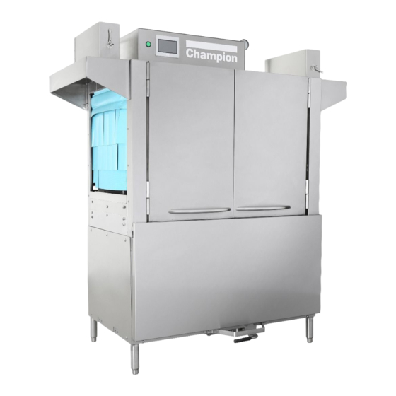
PRO Series
Standard
Rack Conveyor Dishwashers
Models
66 PRO
44 PRO
70FF PRO HD
80HD PRO
116108 rev. E
Printed in the USA
Advertisement
Table of Contents

Related Manuals for Champion PRO Series


Summary of Contents for Champion PRO Series
- Page 1 Installation Manual PRO Series Standard Rack Conveyor Dishwashers Models 66 PRO 44 PRO 70FF PRO HD 80HD PRO 44 PRO LISTED Issue Date: 7.1.19 Manual P/N www.championindustries.com 116108 rev. E For machines beginning with S/N RE19038937 and above 3765 Champion Boulevard 2674 N.
- Page 2 National Service Department In Canada: In the USA: Toll-free: (800) 263-5798 Toll-free: (800) 858-4477 Tel: (905) 562-4195 Tel: (336) 661-1556 Fax: (905) 562-4618 Fax: (336) 661-1660 email: service@moyerdiebellimited.com email: service@championindustries.com ATTENTION The model no., serial no., voltage, Hz and phase are needed to identify your machine and to answer questions.
- Page 3 Product Registration Two ways to REGISTER YOUR PRODUCT and ACTIVATE YOUR WARRANTY. 4:34 PM • Visit our website at www.championindustries.com and register your product online. • Use the fax form on the next page and fax to 1-800 661-1660.
- Page 4 Product Registration PRODUCT REGISTRATION BY FAX COMPLETE THIS FORM AND FAX TO: (336) 661-1660 in the USA 1-(800) 204-0109 in Canada PRODUCT REGISTRATION CARD Model Serial # Date of Installation: Company Name: Address: (Street) State/Province Zip/Postal Code Telephone #: ( Contact: Installation Company: Address:...
- Page 5 Revision History Revision History Specifications are subject to change based on continual product improvement. Equipment owners may request a revised manual, at no charge, by calling 1 (800) 858-4477 in the USA or 1(800) 263-5798 in Canada. Revision Revised Serial Number Description Date Pages...
-
Page 6: Limited Warranty
(b) 90 days after installation, whichever occurs first. In the event that The Company elects to repair, the labor and work to be performed in connection with the warranty shall be done during regular working hours by a Champion authorized service technician. -
Page 7: Table Of Contents
Table of Contents Table of Contents Revision History ..........................i Limited Warranty ......................... ii Model Descriptions ........................iv Installation ....................1 Receiving and Placement ..................1 Installation Codes/Safety Symbols ..............2 Table Connections ....................3 Hot Water Connection ..................4 Steam Connection ....................5 Drain Connection ....................7 Cold Water Connection for Drain Water Tempering Valve .........8 Ventilation - Vent Hood Fan Control ..............9 Ventilation - Pant Leg Duct Settings ..............10... -
Page 8: Model Descriptions
Model Descriptions 44 PRO 44" single tank 66 PRO 44" single tank with 22" prewash 70FF PRO 44" single tank with front feed 26" prewash 80FF PRO 44" single tank with 36" heavy duty prewash... -
Page 9: Installation
Installation Receiving 1. Inspect the machine for damage and immediately report the damage to a supervisor. 2. Check the inside of the machine for accessories and installation parts. 3. Register your machine by fax or online as soon as possible. WARNING: Use extreme caution to prevent damage to the machine when removing from pallet. -
Page 10: Installation Codes/Safety Symbols
Installation Installation Codes The installation of the dishwasher must comply with all local electrical, plumbing, health and safety codes or in the absence of local codes, installed in accordance with the applicable requirements in the National Electrical Code, NFPA 70, Canadian Electrical Code (CEC), Part 1, CSA C22.1;... -
Page 11: Table Connections
Installation Table Connections NOTE: Tables should be installed after the machine is placed in its final location, properly leveled and its height properly adjusted. The standard load height for the dishwasher is 34" [864 mm]. When installing the dish tables: 1. -
Page 12: Hot Water Connection
Installation Hot Water Connection Connect the plumbing in accordance with the specifications below. WATER MINIMUM 3/4" NPT HOT WATER SUPPLY LINE. MINIMUM 1/2" NPT HOT WATER SUPPLY LINE. CAUTION: To prevent damage to the dishwasher supply valves, the installing plumber must thoroughly flush debris from the water supply line before connecting it to the dishwasher. -
Page 13: Steam Connection
Installation Steam Connections STEAM CAUTION: The dishwasher steam connections must comply with all local plumbing, health and safety codes. Damage caused by improper installation is not covered by the limited warranty CHECK THE STEAM SUPPLY PRESSURE REQUIREMENTS PRIOR TO CONNECTING THE STEAM SUPPLY LINES. STANDARD REQUIRED STEAM SUPPLY PRESSURE IS 10-30 PSI. - Page 14 Installation Steam Plumbing and Electrical Drawing 44" 41 3 4 " 41" 31 1 4 " 30" 12 3 4 " 2 " 12 1 2 " 10" 16" 26 11 16 " STACK 6 3 4 " 20" DOOR CLEARANCE 2"...
-
Page 15: Drain Connection
Installation Drain Connection Connect the drain in accordance with the specifications below. DRAIN GRAVITY DRAIN- 1" NPT DRAIN CONNECTION LOCATED UNDERNEATH MACHINE. MAX FLOW IS 17 US GAL/MIN. USE A DIRECT OR INDIRECT CONNECTION TO THE BUILDING DRAIN IN ACCORDANCE WITH LOCAL CODE. FOR PREWASH MACHINES, CONNECTION IS AT THE LOAD END. -
Page 16: Cold Water Connection For Drain Water Tempering Valve
Installation Cold Water Connection Drain Water Tempering, (DWT), Valve COLD MINIMUM 1/2" NPT COLD WATER SUPPLY LINE. WATER MINIMUM INCOMING MAXIMUM INCOMING PRESSURE WATER TEMPERATURE SUPPLY 36°F/ 2°C 60 PSI/414 kPa CAUTION: To prevent damage to the dishwasher supply valves, the installing plumber must thoroughly flush debris from the water supply line before connecting it to the dishwasher. -
Page 17: Ventilation - Vent Hood Fan Control
Installation Ventilation - Vent Hood Fan Control Standard model installations using an approved vent hood may require a vent fan signal. This signal is supplied by the dishwasher control circuit. A qualified installer must connect a signal circuit to the fuse holder and a common neutral terminal provided. -
Page 18: Ventilation - Pant Leg Duct Settings
Installation Ventilation - Pant Leg Duct Settings LOAD END 200 CFM @ 1/4"SP/71 L/SEC UNLOAD END 400 CFM @ 1/4" SP/189 L/SEC. MINIMUM OF SIX KITCHEN AIR CHANGES PER HOUR RECOMMENDED. TWO 4' X 16" VENT STACKS WITH ADJUSTABLE DAMPERS ARE SUPPLIED WITH THE MACHINE. -
Page 19: Detergent Dispenser Connection
Installation Detergent Dispenser Connection WASH TANK CAPACITY IS 17 US GAL./14.2 IMP. GAL/64.4 L. USE A NON-CHLORINATED COMMERCIAL GRADE DETERGENT. 7/8" DIAMETER HOLES ARE PROVIDED IN THE TANK. FUSED 120VAC 0.5 AMP MAX LOAD DETERGENT SIGNAL CONNECTION IS PROVIDED INSIDE THE CONTROL CABINET. THE DETERGENT SIGNAL IS ENABLED THROUGHOUT THE WASH CYCLE. -
Page 20: Rinse-Aid Dispenser Connection
Installation Rinse-Aid Dispenser Connection RINSE = 0.48 US GAL/RACK, 0.40 IMP. GAL/RACK, 1.82 L/RACK R /A 1/8" NPT PIPE PLUG PROVIDED IN FINAL RINSE PIPING. FUSED 120VAC 0.5 AMP MAX LOAD RINSE AID SIGNAL CONNECTION IS PROVIDED INSIDE THE CONTROL CABINET. 0.5A Fig. - Page 21 Instaillation Electrical Connections The installation of the dishwasher must comply with all local electrical, plumbing, health and safety codes or in the absence of local codes, installed in accordance with the applicable requirements in the National Electrical Code, NFPA 70, Canadian Electrical Code (CEC), Part 1, CSA C22.1;...
-
Page 22: Electrical Connections
Installation Electrical Connections - Change 1-Point to 2-Point Electrical Connection COMPARE THE ELECTRICAL SUPPLY WITH THE MACHINE ELECTRICAL CONNECTION DATA PLATE BEFORE CONNECTING THE POWER TO THE MACHINE. THE DATA PLATE IS ADJACENT TO THE INPUT TERMINAL BLOCKS. 1-POINT CONNECTION MACHINES HAVE JUMPERS BETWEEN THE INPUT BLOCKS. - Page 23 Installation To convert a 1-point connection machine to a 2-point connection machine. Open the control cabinet and remove the jumpers, (Fig. 12), between 'Dishwasher' terminal block and the 'Booster' terminal block. Cover the existing 1-point connection data plate, (Fig. 13), with the 2-point connection data plate, (Fig.
-
Page 24: Check Motor Rotation
Installation Electrical Connections - Check Motor Rotation All motors are phased the same at the factory. Reverse L1 and L2 at the main terminal block to change motor direction of all motors. Fig. 16 shows the rotation arrow label on the rear pump housing. Fig. -
Page 25: 21Kw To 12Kw Booster Conversion
Installation Electrical Connections- 21 kW to 12kW Booster Conversion ATTENTION The booster is shipped from the factory wired for 21kW operation. For 12kW operation, the booster must be reconnected as shown below. 21kW Booster 21kW to 12kW Booster Conversion Disconnect all power from the unit. Remove the booster cover. - Page 26 Installation HOW TO MANUALLY OPERATE NEW PRO DRAIN VALVE Electric Drain Valve, P/N 117014 Beginning with S/N: RP19062022, Effective 7/1/19 • The new electric drain valve does not have a manual lever as the Dependo-Drain. • To manually operate the new valve, four 2.5mm socket allen screws must be removed, the valve coil removed, and the valve globe rotated with pliers.
Need help?
Do you have a question about the PRO Series and is the answer not in the manual?
Questions and answers